Downloaded 507 times

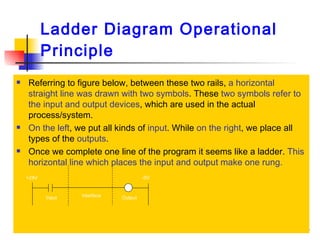
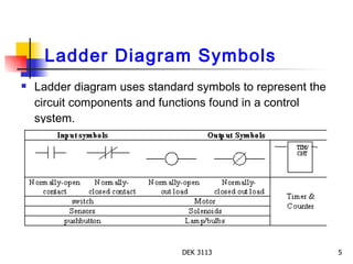
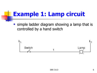
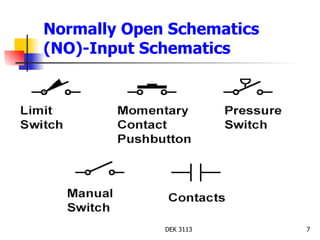
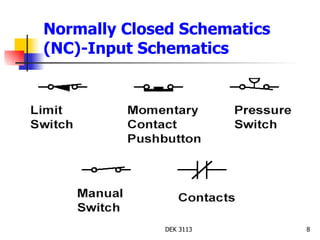
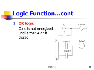
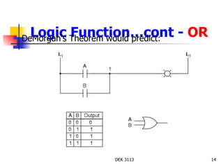
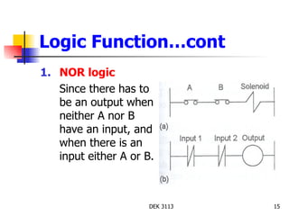
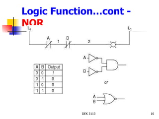
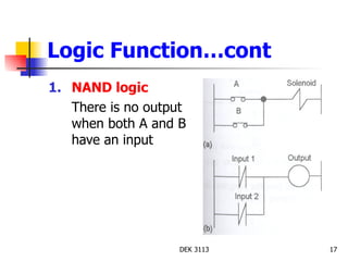
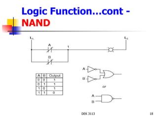
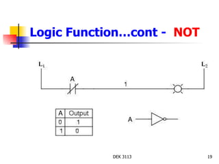
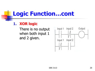
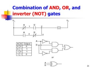


Ladder diagrams are a type of graphic language used to represent logic systems for industrial control. They resemble a ladder, with two vertical power rails and circuits connected horizontally in rungs. Standard symbols are used to represent components like switches, relays, and outputs. Logic functions like AND, OR, and NOT can be depicted using these symbols. Ladder diagrams are used to program PLCs and show control circuits for machines, depicting inputs, logic functions, and outputs.