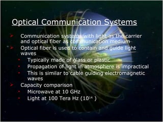
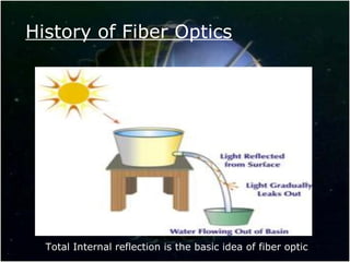
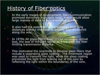
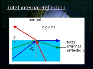
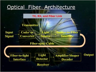
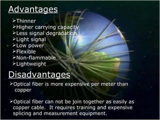
Optical Fiber Communication
Contents
 Introduction
 History of optical fiber
 Optical fiber architecture &
components
 Basic Model
 Types of optical fiber
 Advantages
 Disadvantages
Optical Communication Systems
 Communication systems with light as the carrier
and optical fiber as communication medium
 Optical fiber is used to contain and guide light
waves
• Typically made of glass or plastic
• Propagation of light in atmosphere is impractical
• This is similar to cable guiding electromagnetic
waves
 Capacity comparison
• Microwave at 10 GHz
• Light at 100 Tera Hz (1014
)
History of Fiber Optics
Total Internal reflection is the basic idea of fiber optic
History of Fiber optics
 In the early stages of development, fiber communication
promised extremely high data rates, which would allow
large masses of data to be transmitted quickly.
 It also had the potential for transmission over long
distances without the need to amplify and retransmit
along the way.
 In 1970s All glass fibers experienced excessive optical
loss, the loss of the light signal as it traveled the fiber
limiting transmission distance.
 This motivated the scientists to develop glass fibers that
include a separating glass coating. The innermost region
was used to transmit the light, while the glass coating
prevented the light from leaking out of the core by
reflecting the light within the boundaries of the core.
Total internal Reflection
A little about Light
 When electrons are excited and
moved to a higher energy state
they absorb energy
 When electrons are moved to a
lower energy state  loose
energy  emit light
 photon of light is generated
 Energy (joule) = h.f
 Planck’s constant: h=6.625E-23
Joule.sec
 f is the frequency
Optical Fiber Architecture
Transmitter
Input
Signal
Coder or
Converter
Light
Source
Source-to-Fiber
Interface
Fiber-to-light
Interface
Light
Detector
Amplifier/Shaper
Decoder
Output
Fiber-optic Cable
Receiver
TX, RX, and Fiber Link
Optical Fiber Architecture –
Components
 Light source:
 Amount of light emitted is proportional to the drive current
 Two common types:
 LED (Light Emitting Diode)
 ILD (Injection Laser Diode)
 Source–to-fiber-coupler (similar to a lens):
 A mechanical interface to couple the light emitted by the
source into the optical fiber
 Light detector:
Detector is the receiving end of a fiber optic link.
 PIN (p-type-intrinsic-n-type)
 APD (avalanche photo diode)
 Both convert light energy into current
BASIC MODEL
 The bandwidth of the fiber optic communication
system, which determines the maximum data rate,
depends on the major components of the system.
 The information signal to be transmitted may be
voice, video or computer data.
 The first step is to convert the information into a
form compatible with the communications medium.
 This is usually done by converting continuous
analog signals such as voice and video (TV) signals
into a series of digital pulses.
Cont…
 These digital pulses are then used to flash a
powerful light source (i.e.) off and on very
rapidly, the light source is usually a light emitting
diode (LED), which is a semiconductor device.
 The light beam pulses are then fed into a fiber –
optic cable where they are transmitted over long
distances.
 At the receiving end, a light sensitive device
known as a photocell or light detector is used to
detect the light pulses.
Cont…
 This photocell or photo detector converts the
light pulses into an electrical signal.
 The electrical pulses are amplified and reshaped
back into digital form.
 Both the light sources at the sending end and the
light detectors on the receiving end must be
capable of operating at the same data rate.
 The circuitry that drives the light source and the
circuitry that amplifies and processes the
detected light must both have suitable high-
frequency response.
Cont…
 They are fed to a decoder, such as a Digital – to
– Analog converter (D/A), where the original
voice or video is recovered.
 In very long transmission systems, repeater units
must be used along the way.
 Special relay stations are used to pick up light
beam, convert it back into electrical pulses that
are amplified and then retransmit the pulses on
another beam.
 But despite the attenuation problem, the loss is
less than the loss that occurs with the electric
cables.
How Does fiber optic transmit
light
Optical Fiber Construction
 Core – thin glass
center of the fiber
where light travels.
 Cladding – outer
optical material
surrounding the core
(refractive index less
than that of core)
 Buffer Coating –
plastic coating that
protects the fiber.
Fiber Types
 Plastic core and cladding
 Glass core with plastic cladding PCS
(Plastic-Clad Silicon)
 Glass core and glass cladding SCS:
Silica-clad silica
 Under research: non silicate: Zinc-
chloride
• 1000 time as efficient as glass
• Modes of operation (the path which the
light is traveling on)
Core Cladding
Types Of Optical Fiber
Single-mode step-index Fiber
Multimode step-index Fiber
Multimode graded-index Fiber
n1 core
n2 cladding
no air
n2 cladding
n1 core
Variable
n
no air
Light
ray
Index profile
Optical fibers are the actual media that guides the lightOptical fibers are the actual media that guides the light
There are three types of fiber optic cable commonly usedThere are three types of fiber optic cable commonly used
Single-mode &Multi-mode
step-index Fiber
Advantages:
 Minimum dispersion: all rays take same path,
same time to travel down the cable. A pulse can
be reproduced at the receiver very accurately.
 Less attenuation, can run over longer distance
without repeaters.
 Larger bandwidth and higher information rate
Multimode step-index Fibers:
 inexpensive
 easy to couple light into Fiber
 result in higher signal distortion
 lower TX rate
Acceptance Cone & Numerical Aperture
n2 cladding
n2 cladding
n1 core
Acceptance
Cone
Acceptance angle, θc, is the maximum angle in which external light
rays may strike the air/Fiber interface and still propagate down the
Fiber .
Here - n1 belongs to core and n2 refers to cladding)
- If the angle is too large  light will be lost in cladding
- If the angle is small enough  the light reflects into core and
propagates
2
2
2
1
1
sin nnC −= −
θ
θC
Losses In Optical Fiber Cables
The predominant losses in optic Fibers are:
 absorption losses due to impurities in the
Fiber material
 material or Rayleigh scattering losses due to
microscopic irregularities in the Fiber
 chromatic or wavelength dispersion because
of the use of a non-monochromatic source
 radiation losses caused by bends and kinks in
the Fiber
 pulse spreading or modal dispersion due to
rays taking different paths down the Fiber
(µs/km)
 coupling losses caused by misalignment &
imperfect surface finishes
Scattering & Dispersion
Advantages
Thinner
Higher carrying capacity
Less signal degradation
Light signal
Low power
Flexible
Non-flammable
Lightweight
Disadvantages
Optical fiber is more expensive per meter than
copper
Optical fiber can not be join together as easily as
copper cable. It requires training and expensive
splicing and measurement equipment.
Areas of Application
Telecommunications
Local Area Networks
Cable TV
CCTV
Optical Fiber Sensors
Optical fiber

Optical fiber

  • 1.
  • 2.
    Contents  Introduction  Historyof optical fiber  Optical fiber architecture & components  Basic Model  Types of optical fiber  Advantages  Disadvantages
  • 3.
    Optical Communication Systems Communication systems with light as the carrier and optical fiber as communication medium  Optical fiber is used to contain and guide light waves • Typically made of glass or plastic • Propagation of light in atmosphere is impractical • This is similar to cable guiding electromagnetic waves  Capacity comparison • Microwave at 10 GHz • Light at 100 Tera Hz (1014 )
  • 4.
    History of FiberOptics Total Internal reflection is the basic idea of fiber optic
  • 5.
    History of Fiberoptics  In the early stages of development, fiber communication promised extremely high data rates, which would allow large masses of data to be transmitted quickly.  It also had the potential for transmission over long distances without the need to amplify and retransmit along the way.  In 1970s All glass fibers experienced excessive optical loss, the loss of the light signal as it traveled the fiber limiting transmission distance.  This motivated the scientists to develop glass fibers that include a separating glass coating. The innermost region was used to transmit the light, while the glass coating prevented the light from leaking out of the core by reflecting the light within the boundaries of the core.
  • 6.
  • 7.
    A little aboutLight  When electrons are excited and moved to a higher energy state they absorb energy  When electrons are moved to a lower energy state  loose energy  emit light  photon of light is generated  Energy (joule) = h.f  Planck’s constant: h=6.625E-23 Joule.sec  f is the frequency
  • 8.
    Optical Fiber Architecture Transmitter Input Signal Coderor Converter Light Source Source-to-Fiber Interface Fiber-to-light Interface Light Detector Amplifier/Shaper Decoder Output Fiber-optic Cable Receiver TX, RX, and Fiber Link
  • 9.
    Optical Fiber Architecture– Components  Light source:  Amount of light emitted is proportional to the drive current  Two common types:  LED (Light Emitting Diode)  ILD (Injection Laser Diode)  Source–to-fiber-coupler (similar to a lens):  A mechanical interface to couple the light emitted by the source into the optical fiber  Light detector: Detector is the receiving end of a fiber optic link.  PIN (p-type-intrinsic-n-type)  APD (avalanche photo diode)  Both convert light energy into current
  • 10.
    BASIC MODEL  Thebandwidth of the fiber optic communication system, which determines the maximum data rate, depends on the major components of the system.  The information signal to be transmitted may be voice, video or computer data.  The first step is to convert the information into a form compatible with the communications medium.  This is usually done by converting continuous analog signals such as voice and video (TV) signals into a series of digital pulses.
  • 11.
    Cont…  These digitalpulses are then used to flash a powerful light source (i.e.) off and on very rapidly, the light source is usually a light emitting diode (LED), which is a semiconductor device.  The light beam pulses are then fed into a fiber – optic cable where they are transmitted over long distances.  At the receiving end, a light sensitive device known as a photocell or light detector is used to detect the light pulses.
  • 12.
    Cont…  This photocellor photo detector converts the light pulses into an electrical signal.  The electrical pulses are amplified and reshaped back into digital form.  Both the light sources at the sending end and the light detectors on the receiving end must be capable of operating at the same data rate.  The circuitry that drives the light source and the circuitry that amplifies and processes the detected light must both have suitable high- frequency response.
  • 13.
    Cont…  They arefed to a decoder, such as a Digital – to – Analog converter (D/A), where the original voice or video is recovered.  In very long transmission systems, repeater units must be used along the way.  Special relay stations are used to pick up light beam, convert it back into electrical pulses that are amplified and then retransmit the pulses on another beam.  But despite the attenuation problem, the loss is less than the loss that occurs with the electric cables.
  • 14.
    How Does fiberoptic transmit light
  • 15.
    Optical Fiber Construction Core – thin glass center of the fiber where light travels.  Cladding – outer optical material surrounding the core (refractive index less than that of core)  Buffer Coating – plastic coating that protects the fiber.
  • 16.
    Fiber Types  Plasticcore and cladding  Glass core with plastic cladding PCS (Plastic-Clad Silicon)  Glass core and glass cladding SCS: Silica-clad silica  Under research: non silicate: Zinc- chloride • 1000 time as efficient as glass • Modes of operation (the path which the light is traveling on) Core Cladding
  • 17.
    Types Of OpticalFiber Single-mode step-index Fiber Multimode step-index Fiber Multimode graded-index Fiber n1 core n2 cladding no air n2 cladding n1 core Variable n no air Light ray Index profile Optical fibers are the actual media that guides the lightOptical fibers are the actual media that guides the light There are three types of fiber optic cable commonly usedThere are three types of fiber optic cable commonly used
  • 18.
    Single-mode &Multi-mode step-index Fiber Advantages: Minimum dispersion: all rays take same path, same time to travel down the cable. A pulse can be reproduced at the receiver very accurately.  Less attenuation, can run over longer distance without repeaters.  Larger bandwidth and higher information rate Multimode step-index Fibers:  inexpensive  easy to couple light into Fiber  result in higher signal distortion  lower TX rate
  • 19.
    Acceptance Cone &Numerical Aperture n2 cladding n2 cladding n1 core Acceptance Cone Acceptance angle, θc, is the maximum angle in which external light rays may strike the air/Fiber interface and still propagate down the Fiber . Here - n1 belongs to core and n2 refers to cladding) - If the angle is too large  light will be lost in cladding - If the angle is small enough  the light reflects into core and propagates 2 2 2 1 1 sin nnC −= − θ θC
  • 20.
    Losses In OpticalFiber Cables The predominant losses in optic Fibers are:  absorption losses due to impurities in the Fiber material  material or Rayleigh scattering losses due to microscopic irregularities in the Fiber  chromatic or wavelength dispersion because of the use of a non-monochromatic source  radiation losses caused by bends and kinks in the Fiber  pulse spreading or modal dispersion due to rays taking different paths down the Fiber (µs/km)  coupling losses caused by misalignment & imperfect surface finishes
  • 21.
  • 22.
    Advantages Thinner Higher carrying capacity Lesssignal degradation Light signal Low power Flexible Non-flammable Lightweight Disadvantages Optical fiber is more expensive per meter than copper Optical fiber can not be join together as easily as copper cable. It requires training and expensive splicing and measurement equipment.
  • 23.
    Areas of Application Telecommunications LocalArea Networks Cable TV CCTV Optical Fiber Sensors