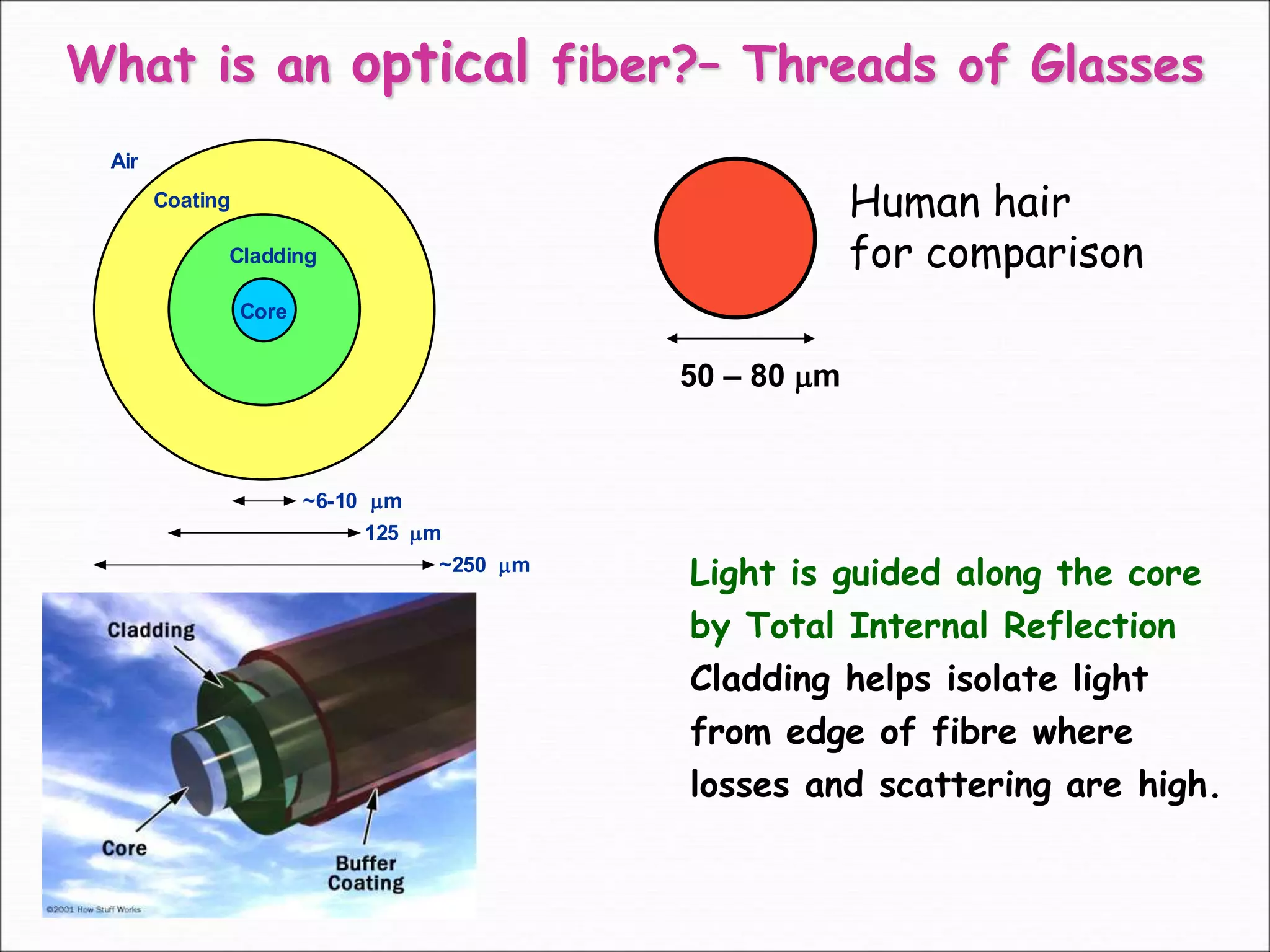
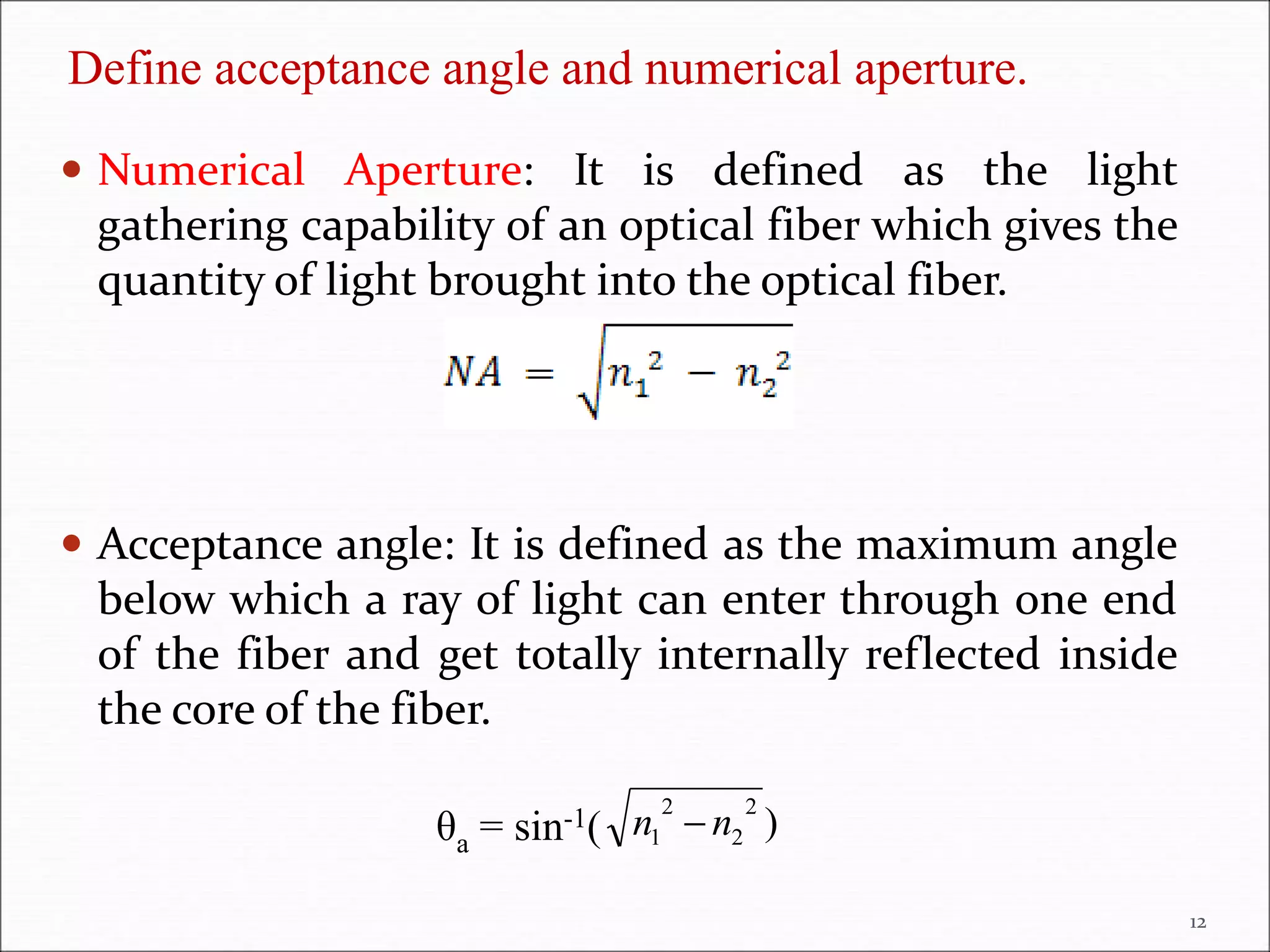
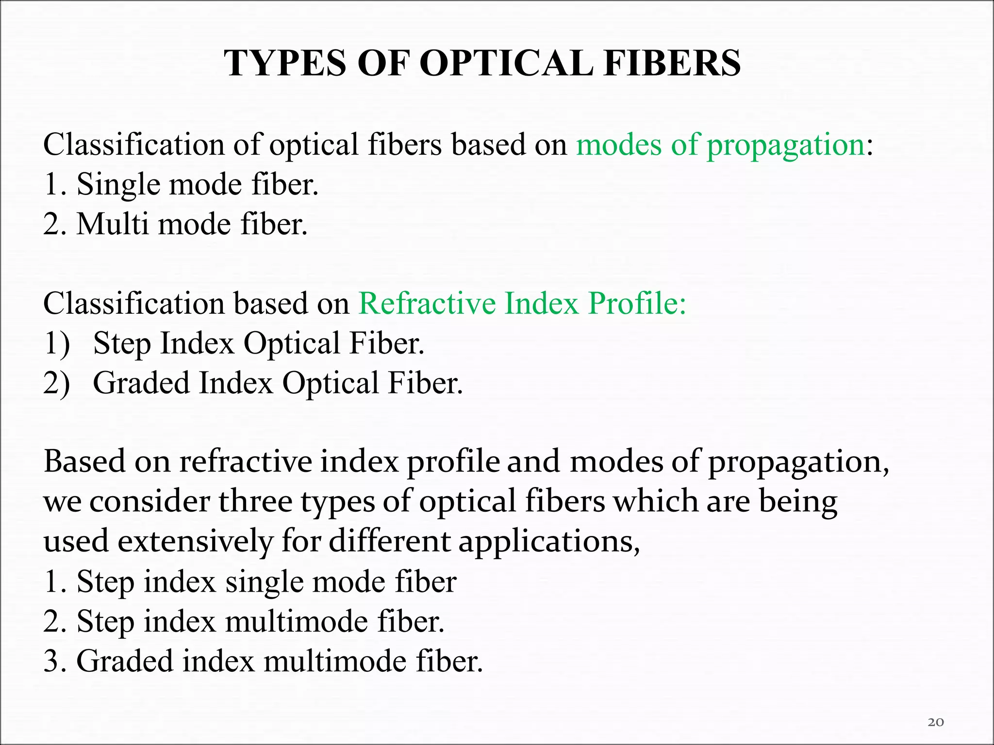
Fiber Optics
PRESIDENCY UNIVERSITY
2
 Introduction
 Principle of propagation of light in Optical fibers
Advantages of Optical fibers.
Acceptance angle and Numerical aperture.
Types of optical fibers.
Losses in optical fibers: Attenuation.
Fiber optic communication system.
Numericals
Plan of the Lecture
3
Telecommunications:
Tele: “Over a distance”
Communications: “Exchange of information”
Similarly,
Telephone: Speech over a distance
Television: Vision over a distance
Telecommunications is the exchange of information over a
certain distance using some type of EQUIPMENT
4
Why Optical Fiber Communication System?
OFC
in everyday life…
Each time you
 Pick up your Phone
 Turn on your TV
 Transmit documents over a Fax
 Give a cashier your Credit Card
 Use a bank ATM
 Surf the World Wide Web
You are using Fiber Optic Communications
technology!!!
Coating
Cladding
Air
Core
~6-10 m
125 m
~250 m
What is an optical fiber?– Threads of Glasses
50 – 80 m
Human hair
for comparison
Light is guided along the core
by Total Internal Reflection
Cladding helps isolate light
from edge of fibre where
losses and scattering are high.
Total Internal Reflection
How does an optical fiber confine light?
8
Principle: Optical fiber works on the principle of total internal reflection. Once
light ray enters into core, it propagates by means of multiple total internal
reflection’s at core-cladding interface.
The light in a fiber-optic cable travels through the core by constantly
bouncing from the cladding, a principle called total internal reflection
(TIR).
How does an optical fiber transmit light?
Advantages of optical fiber communication
 The optical fiber transmission is noise-free.
 As optical fibers make use of light as the medium to transmit signals, it is found to be
one of the fastest mode of communication.
 One of the biggest advantage of optical fibers is high bandwidth.
 Optical fibers are used more easily than copper cables because they are of small
diameter and light weight.
 The light signals conducted in optical fibers are harmless, but in copper cables,
electricity is conducted which is dangerous sometimes.
 The cross-talk becomes negligible in optical fibers.
 Optical fibers have longer life than copper cables.
 Optical fibers are difficult to tap. As they do not radiate electromagnetic energy,
emissions cannot be intercepted.
11
Define acceptance angle and numerical aperture.
12
 Numerical Aperture: It is defined as the light
gathering capability of an optical fiber which gives the
quantity of light brought into the optical fiber.
 Acceptance angle: It is defined as the maximum angle
below which a ray of light can enter through one end
of the fiber and get totally internally reflected inside
the core of the fiber.
θa = sin-1( )
2
2
2
1 n
n 
Numerical Aperture
13
Fig shows how light travels inside fiber optic cable
14
Let no, n1, n2 be the refractive indices of air, core
and cladding
Deriving Expression for Numerical Aperture
15
If the angle of incidence θ is equal to the critical angle for the respective fiber,
then the angle of refraction θr = 900 which means that the ray just grazes along
the core-cladding interface.
From ΔOBC, we have r + θ + 900 = 1800
so r + θ = 900
θ = 900 – r …………………..(1)
Now, applying Snell’s law of refraction at the interface of core and cladding (at
B), we get
n1 sinθ = n2 sinθr …………………..(2)
We know that θ = 900 – r and θr = 900. This happens only when θ = θc (critical
angle). It is noted that the ray (OB) falls at critical angle inside the core only
when it falls at acceptance angle (θa) at the air- fiber interface.
ie, θi = θa
Or we can say that it is the maximum angle of incidence at air-fiber interface
below which total internal reflection will occur inside the core.
So equation (2) can be written as:
n1 sin(900 – r) = n2 sin900 (see equation (1))
n1 cos r = n2 (sin900 =1)
--------------------------(3)
Now applying Snell’s law at air – fiber interface at O,
16
nosin θa = n1sin r (as θi = θa)
sin θa = n1sin r (no = 1 as air) ……………....(4)
17

18
19
20
Classification of optical fibers based on modes of propagation:
1. Single mode fiber.
2. Multi mode fiber.
Classification based on Refractive Index Profile:
1) Step Index Optical Fiber.
2) Graded Index Optical Fiber.
Based on refractive index profile and modes of propagation,
we consider three types of optical fibers which are being
used extensively for different applications,
1. Step index single mode fiber
2. Step index multimode fiber.
3. Graded index multimode fiber.
TYPES OF OPTICAL FIBERS
Classification based on Modes
21
 Single Mode fibers (SMF): Single mode fiber is optical fiber
that is designed for the transmission of a single ray or mode of light as
a carrier and is used for long-distance signal transmission.
 Multimode Fibers (MMF): Multimode fibers are mostly
designed for the transmission of multiple rays or multiple modes of
light signals and is mostly used for short distance signal transmission.
22
Classification based on Index
Profile
23
24
 Step Index optical Fiber : the refractive index of core throughout the
fiber is uniform and undergoes an abrupt change when it reaches the cladding.
The refractive index of core will be n1 throughout the core with no irregularity.
 Graded Index optical Fiber: The refractive index of core is made to
vary gradually such that is maximum at the center and minimum at the end or
core cladding interface. This will affect the direction of the light signals inside
the core.
1. Step-Index Single-Mode Fiber
 Only one mode propagates.
 This is achieved by very small core diameter (5-10 µm)
 Highest bit rate, most widely used in telecom
Classification based on refractive index profile and modes of
propagation
Advantages
1. Limited data loss/ signal loss.
2. Used in Long distance communication.
Disadvantage
 It is costlier compared to multimode fibers.
 laser source can only be used for launching signal. It is
difficult to couple light signals because of small core
radius compared to multimode fibers.
Applications
 It is used as undersea cables.
 Telecommunication systems.
 Defense applications.
26
2. Step Index Multimode Fiber
 Large radius of the core (50 - 100μm).
 Multiple modes can be supported inside the core.
 Refractive index of the core is uniform throughout and there is
an abrupt change in the refractive index at the core-cladding
interface.
 It takes different paths to travel (note that the velocity of the
modes will be same), different modes will reach at different
time. Dispersion losses more in multimode fibers compared to
single mode fibers.
Advantages:
 Source- Either laser or LED can be used as the source of
light.
 it is comparably cheap and thereby can be used for
short distance communications.
 Disadvantage-They cannot be used over long distances.
 Application-They are used in data links.
28
3. Graded-Index Multimode Fiber
 Core refractive index is maximum at the centre and decreases
gradually until it meets core-cladding boundary.
 Modes propagating closer to the cladding-longer distance-
propagate at higher speed (less RI).
 Modes traveling around the centerline-shortest distance-travel at
the lowest speed (high RI).
 It is just a clever modification of refractive index profile to
reduce dispersion losses as in this case light signals or
different modes will almost reach at the same time reducing
dispersion losses.
A clever modification in the Refractive Index profile
Advantage
 Dispersion losses are less and bandwidth is high
compared to step index multimode fibers.
 Source- Either laser or LED can be used as the source of
light.
Disadvantage
 It is costlier compared to step index multimode fibers
Applications
 Mostly used in Local Area Networks (LAN).
 Used in inter organization communication networks.
30
Attenuation
 Loss of light energy when it propagates through the fiber
is known as transmission loss or attenuation.
31
Losses in Optical fibers
32
Causes of Attenuation
Attenuation in optical fibers is caused by,
1) Absorption: Absorption of energy may be by the fiber material, called
intrinsic absorption, or by the impurities present in it, called extrinsic
absorption.
2) Scattering: Impurities and structural inhomogeneity in the fiber could
cause scattering of light passing through it, resulting in loss of energy of
the signal. The scattering involved is Rayleigh’s scattering, which
depends on and therefore is more for smaller wavelengths.
3) Radiation Loss: While laying fiber optic cables they have to be bent at
corners, which result in changes in angle of incidence at the core-cladding
interface. This results in partial loss of light by refraction, as shown in figure.
Loss also happens when the core-cladding interface has microscopic
irregularities. This kind of loss is called radiation loss
33
Working: Transmitter block:
 Coder/converter which will convert the analog
signals into the digital form (Pulse signal).
 The signal is then fed into a light source
transmitter circuit which will basically convert the
electrical signal to light signal by emitting the
signal through a laser or LED.
 This will be in the pulse form (light turns off and
on at rapid rate) and is then launched into an
optical fiber cable of a particular length required.
34
Working: Receiver block:
 Light signals will be incident on a photo cell or light
detector followed by the amplifier which will amplify the
signals (Optical losses will be incurred by the signal after
going through the fiber).
 The signals are then passed through shaper circuit which
will shape the waveform of the signal back to the pulse
form. Its purpose is to make the signal better suited to its
required output form.
 The signals are then passed through the decoder will
convert the digital pulse signals to the analog form if it is
required or else directly the digital signals are taken to a
computer system.
35

36
37

Optical fibers

  • 1.
  • 2.
    2  Introduction  Principleof propagation of light in Optical fibers Advantages of Optical fibers. Acceptance angle and Numerical aperture. Types of optical fibers. Losses in optical fibers: Attenuation. Fiber optic communication system. Numericals Plan of the Lecture
  • 3.
    3 Telecommunications: Tele: “Over adistance” Communications: “Exchange of information” Similarly, Telephone: Speech over a distance Television: Vision over a distance Telecommunications is the exchange of information over a certain distance using some type of EQUIPMENT
  • 4.
    4 Why Optical FiberCommunication System?
  • 5.
    OFC in everyday life… Eachtime you  Pick up your Phone  Turn on your TV  Transmit documents over a Fax  Give a cashier your Credit Card  Use a bank ATM  Surf the World Wide Web You are using Fiber Optic Communications technology!!!
  • 6.
    Coating Cladding Air Core ~6-10 m 125 m ~250m What is an optical fiber?– Threads of Glasses 50 – 80 m Human hair for comparison Light is guided along the core by Total Internal Reflection Cladding helps isolate light from edge of fibre where losses and scattering are high.
  • 7.
    Total Internal Reflection Howdoes an optical fiber confine light?
  • 8.
  • 10.
    Principle: Optical fiberworks on the principle of total internal reflection. Once light ray enters into core, it propagates by means of multiple total internal reflection’s at core-cladding interface. The light in a fiber-optic cable travels through the core by constantly bouncing from the cladding, a principle called total internal reflection (TIR). How does an optical fiber transmit light?
  • 11.
    Advantages of opticalfiber communication  The optical fiber transmission is noise-free.  As optical fibers make use of light as the medium to transmit signals, it is found to be one of the fastest mode of communication.  One of the biggest advantage of optical fibers is high bandwidth.  Optical fibers are used more easily than copper cables because they are of small diameter and light weight.  The light signals conducted in optical fibers are harmless, but in copper cables, electricity is conducted which is dangerous sometimes.  The cross-talk becomes negligible in optical fibers.  Optical fibers have longer life than copper cables.  Optical fibers are difficult to tap. As they do not radiate electromagnetic energy, emissions cannot be intercepted. 11
  • 12.
    Define acceptance angleand numerical aperture. 12  Numerical Aperture: It is defined as the light gathering capability of an optical fiber which gives the quantity of light brought into the optical fiber.  Acceptance angle: It is defined as the maximum angle below which a ray of light can enter through one end of the fiber and get totally internally reflected inside the core of the fiber. θa = sin-1( ) 2 2 2 1 n n 
  • 13.
  • 14.
    Fig shows howlight travels inside fiber optic cable 14 Let no, n1, n2 be the refractive indices of air, core and cladding Deriving Expression for Numerical Aperture
  • 15.
    15 If the angleof incidence θ is equal to the critical angle for the respective fiber, then the angle of refraction θr = 900 which means that the ray just grazes along the core-cladding interface. From ΔOBC, we have r + θ + 900 = 1800 so r + θ = 900 θ = 900 – r …………………..(1) Now, applying Snell’s law of refraction at the interface of core and cladding (at B), we get n1 sinθ = n2 sinθr …………………..(2) We know that θ = 900 – r and θr = 900. This happens only when θ = θc (critical angle). It is noted that the ray (OB) falls at critical angle inside the core only when it falls at acceptance angle (θa) at the air- fiber interface. ie, θi = θa Or we can say that it is the maximum angle of incidence at air-fiber interface below which total internal reflection will occur inside the core. So equation (2) can be written as: n1 sin(900 – r) = n2 sin900 (see equation (1)) n1 cos r = n2 (sin900 =1) --------------------------(3) Now applying Snell’s law at air – fiber interface at O,
  • 16.
    16 nosin θa =n1sin r (as θi = θa) sin θa = n1sin r (no = 1 as air) ……………....(4)
  • 17.
  • 18.
  • 19.
  • 20.
    20 Classification of opticalfibers based on modes of propagation: 1. Single mode fiber. 2. Multi mode fiber. Classification based on Refractive Index Profile: 1) Step Index Optical Fiber. 2) Graded Index Optical Fiber. Based on refractive index profile and modes of propagation, we consider three types of optical fibers which are being used extensively for different applications, 1. Step index single mode fiber 2. Step index multimode fiber. 3. Graded index multimode fiber. TYPES OF OPTICAL FIBERS
  • 21.
  • 22.
     Single Modefibers (SMF): Single mode fiber is optical fiber that is designed for the transmission of a single ray or mode of light as a carrier and is used for long-distance signal transmission.  Multimode Fibers (MMF): Multimode fibers are mostly designed for the transmission of multiple rays or multiple modes of light signals and is mostly used for short distance signal transmission. 22
  • 23.
    Classification based onIndex Profile 23
  • 24.
    24  Step Indexoptical Fiber : the refractive index of core throughout the fiber is uniform and undergoes an abrupt change when it reaches the cladding. The refractive index of core will be n1 throughout the core with no irregularity.  Graded Index optical Fiber: The refractive index of core is made to vary gradually such that is maximum at the center and minimum at the end or core cladding interface. This will affect the direction of the light signals inside the core.
  • 25.
    1. Step-Index Single-ModeFiber  Only one mode propagates.  This is achieved by very small core diameter (5-10 µm)  Highest bit rate, most widely used in telecom Classification based on refractive index profile and modes of propagation
  • 26.
    Advantages 1. Limited dataloss/ signal loss. 2. Used in Long distance communication. Disadvantage  It is costlier compared to multimode fibers.  laser source can only be used for launching signal. It is difficult to couple light signals because of small core radius compared to multimode fibers. Applications  It is used as undersea cables.  Telecommunication systems.  Defense applications. 26
  • 27.
    2. Step IndexMultimode Fiber  Large radius of the core (50 - 100μm).  Multiple modes can be supported inside the core.  Refractive index of the core is uniform throughout and there is an abrupt change in the refractive index at the core-cladding interface.  It takes different paths to travel (note that the velocity of the modes will be same), different modes will reach at different time. Dispersion losses more in multimode fibers compared to single mode fibers.
  • 28.
    Advantages:  Source- Eitherlaser or LED can be used as the source of light.  it is comparably cheap and thereby can be used for short distance communications.  Disadvantage-They cannot be used over long distances.  Application-They are used in data links. 28
  • 29.
    3. Graded-Index MultimodeFiber  Core refractive index is maximum at the centre and decreases gradually until it meets core-cladding boundary.  Modes propagating closer to the cladding-longer distance- propagate at higher speed (less RI).  Modes traveling around the centerline-shortest distance-travel at the lowest speed (high RI).  It is just a clever modification of refractive index profile to reduce dispersion losses as in this case light signals or different modes will almost reach at the same time reducing dispersion losses. A clever modification in the Refractive Index profile
  • 30.
    Advantage  Dispersion lossesare less and bandwidth is high compared to step index multimode fibers.  Source- Either laser or LED can be used as the source of light. Disadvantage  It is costlier compared to step index multimode fibers Applications  Mostly used in Local Area Networks (LAN).  Used in inter organization communication networks. 30
  • 31.
    Attenuation  Loss oflight energy when it propagates through the fiber is known as transmission loss or attenuation. 31 Losses in Optical fibers
  • 32.
    32 Causes of Attenuation Attenuationin optical fibers is caused by, 1) Absorption: Absorption of energy may be by the fiber material, called intrinsic absorption, or by the impurities present in it, called extrinsic absorption. 2) Scattering: Impurities and structural inhomogeneity in the fiber could cause scattering of light passing through it, resulting in loss of energy of the signal. The scattering involved is Rayleigh’s scattering, which depends on and therefore is more for smaller wavelengths. 3) Radiation Loss: While laying fiber optic cables they have to be bent at corners, which result in changes in angle of incidence at the core-cladding interface. This results in partial loss of light by refraction, as shown in figure. Loss also happens when the core-cladding interface has microscopic irregularities. This kind of loss is called radiation loss
  • 33.
  • 34.
    Working: Transmitter block: Coder/converter which will convert the analog signals into the digital form (Pulse signal).  The signal is then fed into a light source transmitter circuit which will basically convert the electrical signal to light signal by emitting the signal through a laser or LED.  This will be in the pulse form (light turns off and on at rapid rate) and is then launched into an optical fiber cable of a particular length required. 34
  • 35.
    Working: Receiver block: Light signals will be incident on a photo cell or light detector followed by the amplifier which will amplify the signals (Optical losses will be incurred by the signal after going through the fiber).  The signals are then passed through shaper circuit which will shape the waveform of the signal back to the pulse form. Its purpose is to make the signal better suited to its required output form.  The signals are then passed through the decoder will convert the digital pulse signals to the analog form if it is required or else directly the digital signals are taken to a computer system. 35
  • 36.
  • 37.