Downloaded 311 times

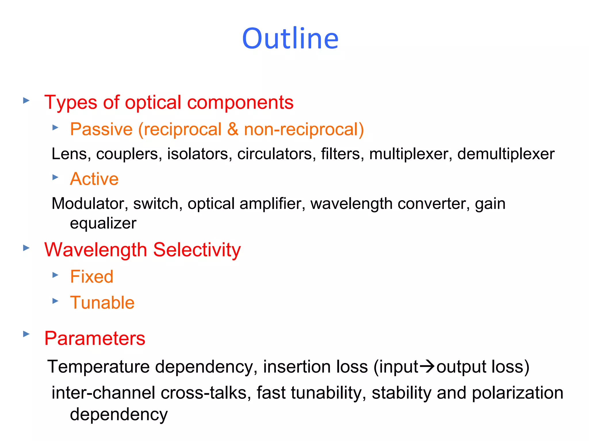


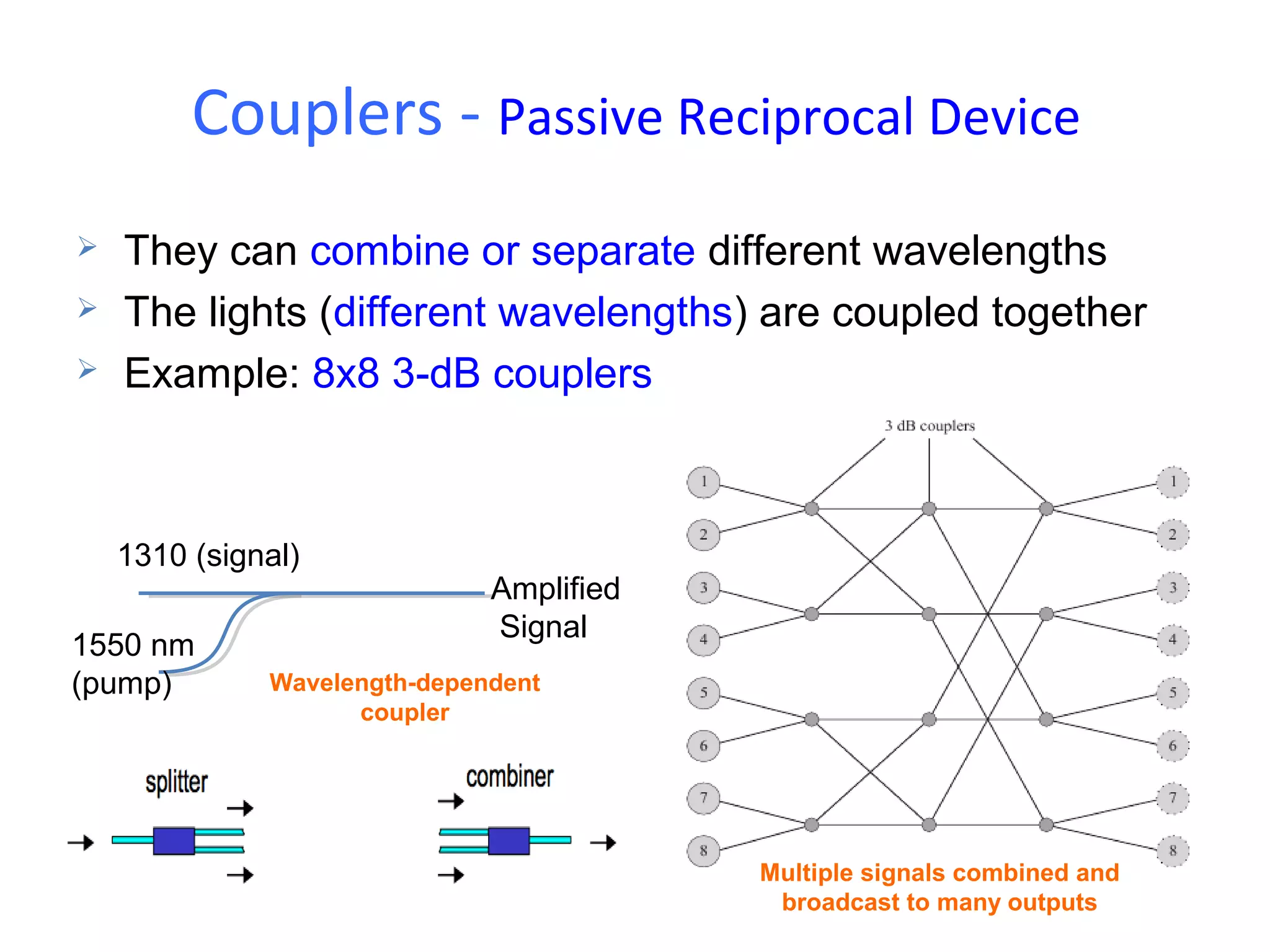


This document discusses various optical components used in fiber optic communication systems. It describes passive components like couplers, isolators, filters, and multiplexers/demultiplexers. It also covers active components such as modulators, switches, optical amplifiers, and wavelength converters. Different technologies for implementing these components are presented, including micro-optics, integrated optics, fiber-based, and hybrid approaches. Key parameters and requirements for optical components are also outlined.