Downloaded 1,402 times


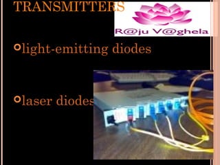
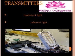


Optical fiber communication uses glass or plastic fibers to transmit light signals for telecommunication. Light from a laser or LED is transmitted through the fiber's core using total internal reflection. Optical fibers have advantages over copper cables including higher bandwidth, less signal degradation, lighter weight, and immunity to electromagnetic interference. Fiber systems use single-mode or multi-mode fibers depending on the transmission distance and bandwidth needs.