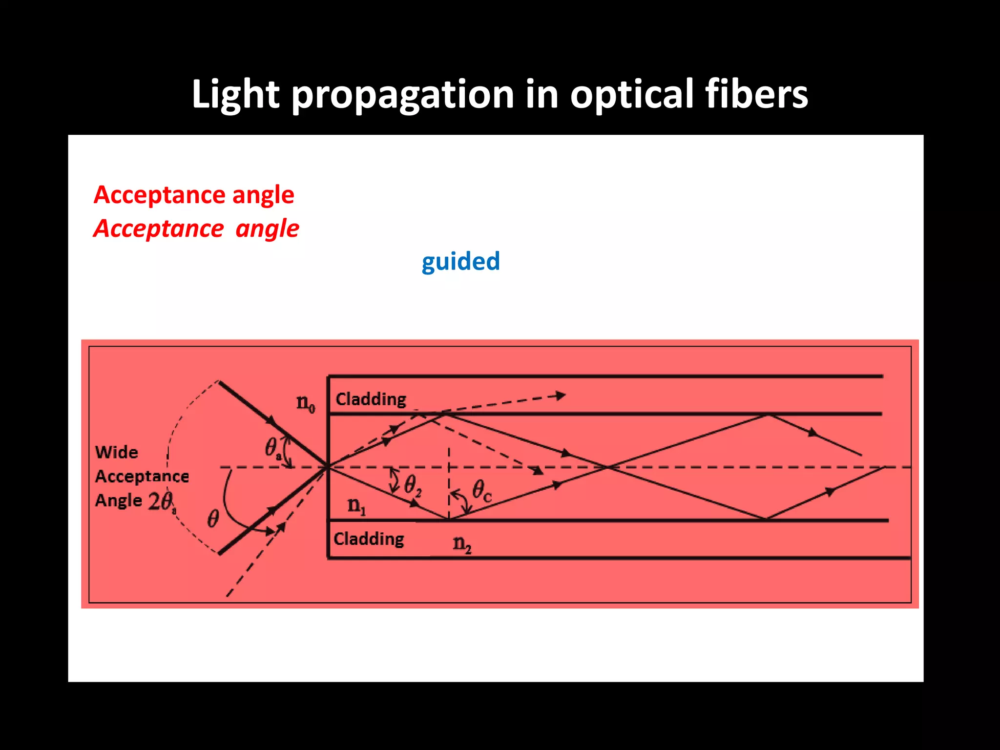
2. Optical Fiber Communication System
Information
source
Electrical
source
Optical
source
Optical
fiber
cableOptical
detector
Electrical
receiver
Destination
Fiber
Optic cable
The primary objective of optical fiber communication system also is to transfer the
signal containing information (voice, data, video) from the source to the
destination by sending light through an optical fiber. The light forms an
electromagnetic carrier wave that is modulated to carry information
The process of communicating using fiber-optics involves the following basic steps:
Creating the optical signal using a transmitter, Relaying the signal along the fiber,
ensuring that the signal does not become too distorted or weak, and Receiving the
optical signal and converting it into an electrical signal.
6. Regenerative Repeaters and Optical Amplifiers
Because of loss or dispersion, there is always a limit to the length of a
single span of fiber-optic cable. When distances are great, some form of
gain must be provided, using one of two different ways:
– Change the signal to electrical form, amplify it, regenerate it if it is digital, and
then convert it back to an optical signal
– Simply amplify the optical signal
Signal
Source
Optical
Transmitter
Optical
Receiver
Signal
Destination
Regenerative Repeater
Signal
Source
Optical
Transmitter
Optical
Receiver
Signal
Destination
Optical
Receiver
Optical
Transmitter
Pulse
Shaper
Signal
Source
Optical
Transmitter
Optical
Receiver
Signal
Destination
Optical
Amplifier
7. Need of Fiber Optic Communications
Extremely high data rates,
Suitable for long-distance transmission
No need to amplify and retransmit along the way.
Speed limit of electronic processing,
Limited bandwidth of copper/coaxial cables.
Optical fiber has very high-bandwidth (~30 THz)
Optical fiber has very low loss (~0.25dB/km @1550nm)
11. Transmission windows
Band Description Wavelength Range
O band original 1260 to 1360 nm
E band extended 1360 to 1460 nm
S band short wavelengths 1460 to 1530 nm
C band
conventional
(erbium window)
1530 to 1565 nm
L band long wavelengths 1565 to 1625 nm
U band Ultra-long wavelengths 1625 to 1675 nm
12. The simplest way to view light in fiber optics is by ray theory. In this
theory, the light is treated as a simple ray, shown by a line. An
arrow on the line shows the direction of propagation.
The speed of light in vacuum is: c = 300,000 km/s
However, the speed of light in medium is more slowly,
v = c / n.
The ratio of the velocity of light, c, in vacuum, to the velocity of light
in the medium, v, is the refractive index, n.
n = c / v
Light Propagation in Optical Fibers
13. Light traveling from one material to another causes the
change of speed, which results in the change of light
traveling direction. This deflection of light is called refraction.
Light Propagation in Optical Fibers
14. The relation between incident ray and reflection ray:
r = i (Law of reflection)
The relation between incident ray and refraction ray:
n1sini = n2sint (Snell’s law)
where n1 and n2 are refractive indices of the
incident and transmission regions, respectively.
Light propagation in optical fibers
16. Total internal reflection
From Snell’s law, n1sini = n2sint
if n1 > n2, then sini = (n2/n1) sint < sint,
which leads to i < t, i.e. the angle of refraction is
always greater than the angle of incidence.
Thus, when the angle of refraction t = 90 as
sini = (n2/n1) sint = (n2/n1) sin90 = n2/n1 < 1
the angle of incidence, i, must be less than 90.
Light propagation in optical fibers
17. Critical angle
The angle of incidence that yields an angle of refraction t =
90 is called the critical angle, C.
sinC = n2/n1
When the angle of incidence is greater than the critical angle,
the light will be reflected back into the originating dielectric
medium. This is known as total internal reflection.
Light propagation in optical fibers
18. Light guiding
In order to propagate a long distance in the optical fiber, the light
beam must satisfy the conditions for total internal reflection
Conditions for total internal reflection in optical fiber
Refractive index of fiber core, n1, is greater than refractive index of
fiber cladding n2, i.e. n1 > n2
The incident angle is larger than the critical angle. i > C
Light propagation in optical fibers
19. Acceptance angle
Acceptance angle, a, is the maximum angle over which light rays
entering the fiber will be guided along its core.
Light propagation in optical fibers
20. The acceptance angle is usually measured as the numerical
aperture (NA).
Numerical aperture
At the air-core interface,
n0sina = n1sin2 = n1sin(90 - C)
= n1cosC = n1(1 – sin2C)1/2
= n1[1 – (n2/n1)2]1/2 = (n1
2 - n2
2)1/2 = NA
The value of NA represents the light collecting ability.
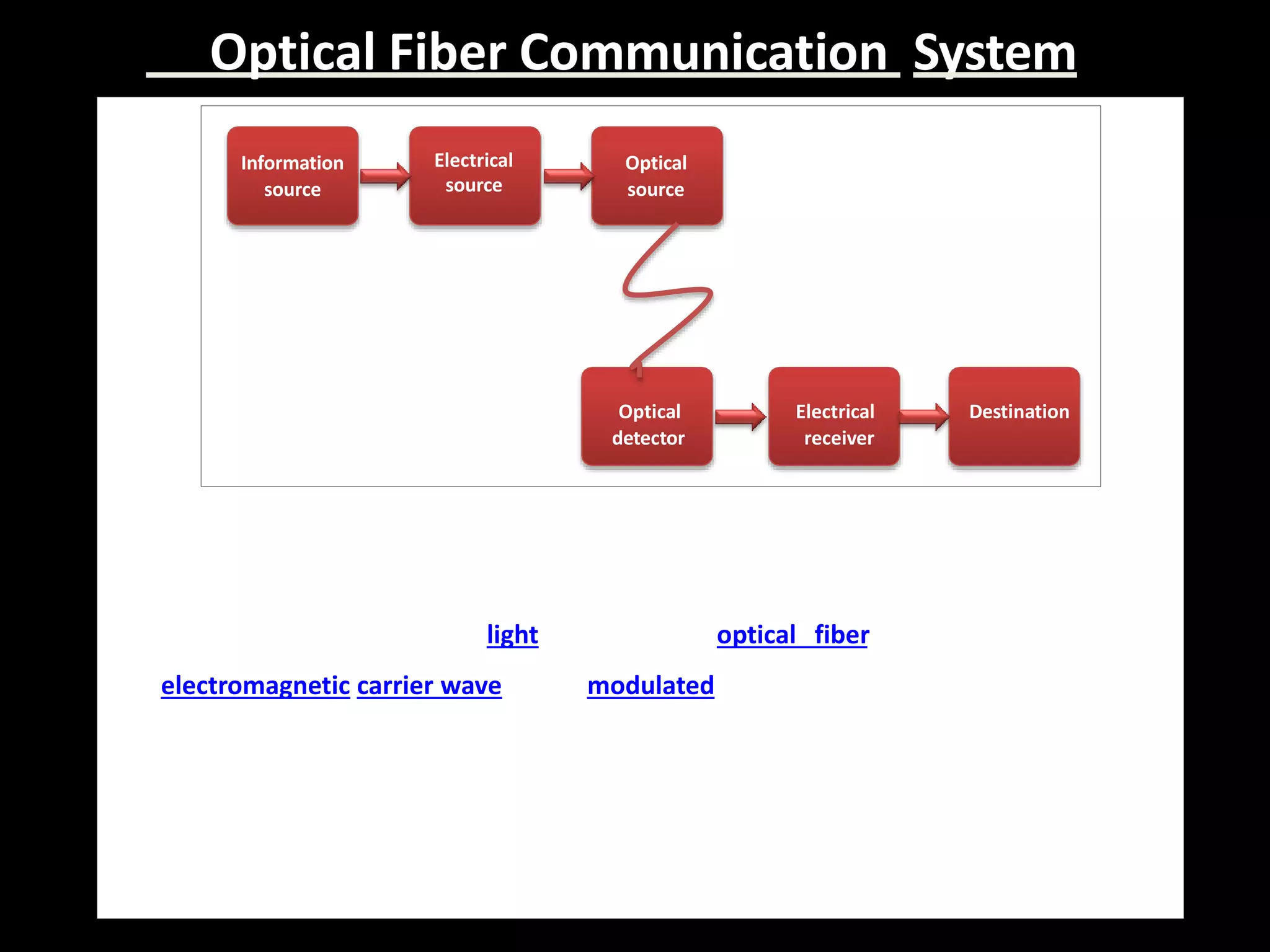
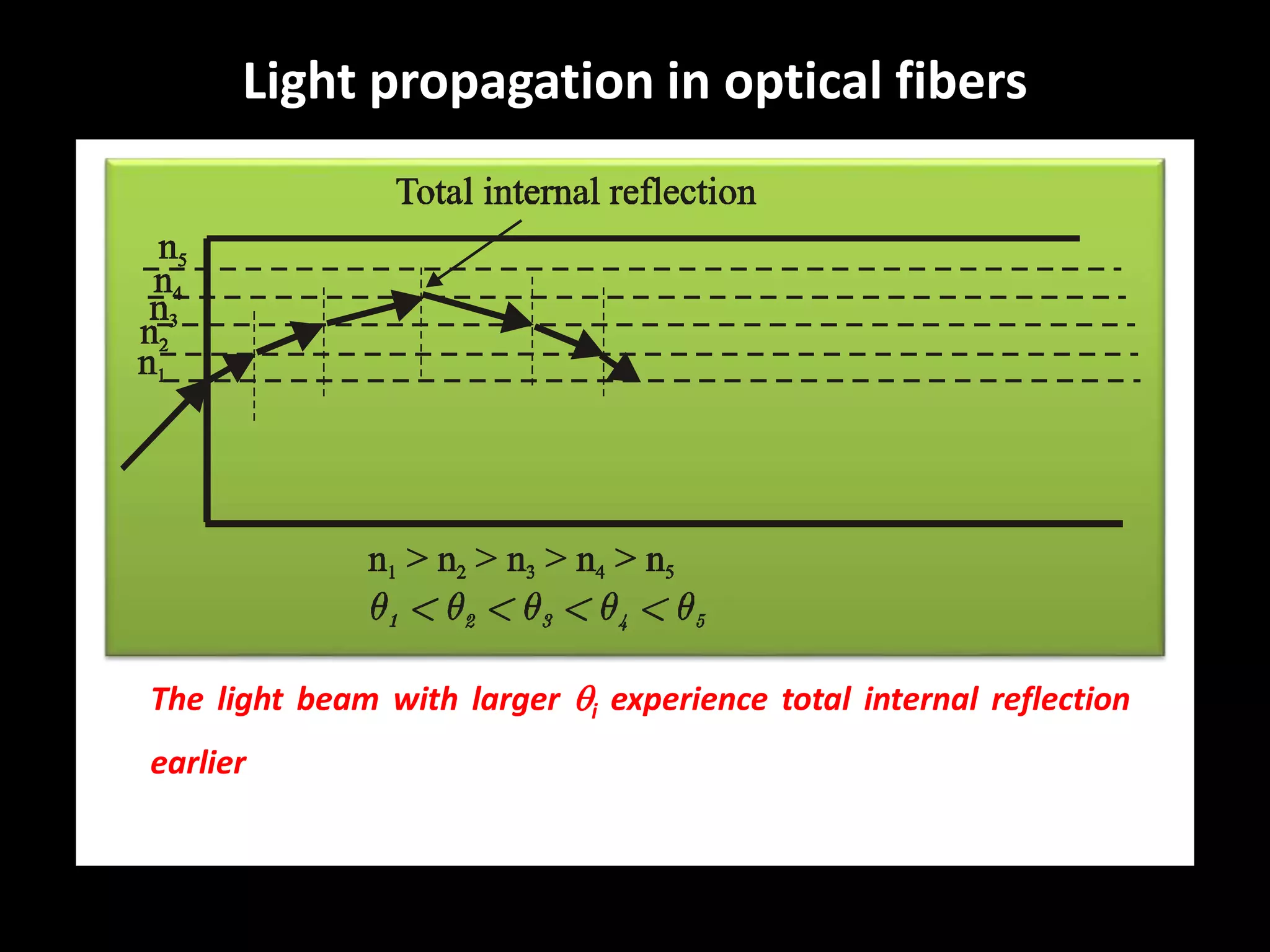
Light propagation in optical fibers
21. The light beam with larger i experience total internal reflection
earlier, light beam with smaller i travels longer distance until it
experience total internal reflection.
Light propagation in optical fibers
22. Single-mode fiber
Carries light pulses along
single path
Multi-mode fiber
Many pulses of light
generated by LED travel at
different angles
Modes of Propagation
23. An optical fiber consists
of a core surrounded by
a cladding.
There are two types of
fibers: step-index fibers
and graded-index fibers.
Modes of Propagation
24. STEP INDEX
• A step-index fiber has a central core with a uniform refractive
index. An outside cladding that also has a uniform refractive
index surrounds the core; however, the refractive index of the
cladding is less than that of the central core.
GRADED INDEX
• In graded-index fiber, the index of refraction in the core
decreases continuously. This causes light rays to bend smoothly
as they approach the cladding, rather than reflecting abruptly
from the core-cladding boundary.
Modes of Propagation
27. Light propagation in graded-index fiber
It guides light by refraction. Its refractive index
decreases gradually away from its center, dropping to
the same as the cladding at the edge of the core.
The change in refractive index causes refraction,
bending light rays back toward the axis as they pass
through layers with lower refractive index.
Modes of Propagation
29. Fibre Attenuation
Attenuation limits how far a signal can travel through a fiber
before it becomes too weak to be detected.
Fibre attenuation is a function of wavelength and it gives a
measure of the loss suffered by the light in the fibre per km of
length travelled.
The attenuation constant, , is given by
where L is the length of the fibre, Pin is the input light power
and Pout is the output light power.
LPP inout //log10 10
Transmission properties of optical fibers
30. • Fiber Attenuation is the loss of the optical power.
• Fiber Attenuation in optical fiber take place due to elements like
coupler, splices, connector and fiber itself.
• A fiber lower attenuation will allow more power to reach a
receiver than with a higher attenuation.
• Fiber Attenuation may be categorised as – (a)Intrinsic (b)Extrinsic
Attenuation
Intrinsic
Absorption Scattering
Extrinsic
Macrobending Microbending
Transmission properties of optical fibers
31. Main types of fiber attenuation:
Absorption, scattering and light coupling loss
Absorption
• Absorption is related to the material composition and the
fabrication process for the fiber, which results in the
dissipation of some of the transmitted optical power as heat
in the waveguide.
Optical power → heat Optical power loss
Transmission properties of optical fibers
32. Scattering
Scattering refers to the process by which the light wave
encounters a particle smaller than its wavelength, with
the results that energy is sent to a new direction.
Transmission properties of optical fibers
33. Bend loss
Bend loss is the loss resulting from bend. Bend can cause the
change of incident angle at which the light hits the core-
cladding boundary.
Transmission properties of optical fibers
35. Dispersion
Dispersion is the
spreading of a light pulse.
Dispersion limits digital
transmission speed by
causing pulses to overlap,
so they cannot be
distinguished. The bit
rate must be low enough
to ensure that pulses do
not overlap.
Transmission properties of optical fibers
36. Three main types of dispersion
Material dispersion
Material dispersion occurs because the refractive index of the
material changes with the optical wavelength.
As n = n(), and n = c / v, then v = c / n()
Different wavelength elements travel at different velocities
through a fiber, even in the same mode.
Transmission properties of optical fibers
37. Waveguide dispersion
It is equivalent to the angle between the ray and the fiber axis
varying with wavelength.
From
For a given mode (e.g. m = 1)
Different lead to different values of 1 and hence results in
different transmission time (in the same mode).
1
( )
cos
2nkd nd
cos 0, 1, 2, ,i
m
m
nkd
Transmission properties of optical fibers
38. Mode dispersion
Mode dispersion arises because
rays follow different paths
through the fiber and
consequently arrive at the
other end of the fiber at
different times.
Different modes travel with
different speeds.
Transmission properties of optical fibers
39. Loss Budget
• The most basic limitation on the length of the fiber-optic link is loss in the
fiber, connectors, and splices
• If the length is too great, the optical power level at the receiver will be
insufficient to produce an acceptable signal-to-noise ratio
• Given the optical power output of the transmitter and the signal level
required by the receiver, a loss budget may be drawn up
• If the losses along the line are enough to reduce the power at the receiver
below minimum requirements, then one of the following needs to occur:
– Increase the transmitter power
– Increase receiver sensitivity
– Decrease the length of the cable
Transmission properties of optical fibers
43. Optical Fiber Cable
relatively new transmission
medium used by telephone
companies in place of long-
distance trunk lines
also used by private companies
in implementing local data
networks
require a light source with
injection laser diode (ILD) or
light-emitting diodes (LED)
fiber to the desktop in the future
43
44. An optical fiber consists of a very thin glasses core (5 mm to 50 mm in
diameter) surrounded by a glass coating called cladding. The glass core and
cladding are enclosed in a protective jacket made of plastic. The refractive
index of the glass used for making core (m) is a little more than the respective
index of the glass used for making the cladding (m2) i.e.m1> m2. In optical
fiber, the value of refractive index of core is 1.52 and the value of refractive
index of cladding is 1.48 respectively. Most optical fibers are made of glass,
although some are made of plastic
Optical Fiber Cable
45. • Core – central tube of very thin size made up of
optically transparent dielectric medium and carries
the light form transmitter to receiver.
• Cladding – Outer optical material surrounding the
core having reflecting index lower than core. It
traps the light in the core by the principle of total
internal reflection.
• Buffer Coating – plastic coating made of silicon rubber
which protects the glass fiber from physical damage
and moisture.
• Modern cables come in a wide variety of sheathings
and armor, designed for direct burial in trenches,
high voltage isolation submarine installation, and
insertion in paved streets.
Optical Fiber Cable
50. Single-Mode Fibers
• Single-mode fibers – used to transmit one signal per fiber (used in
telephone and cable TV). They have small cores(9 microns in
diameter) and transmit infra-red light from laser.
• Single-mode fiber’s smaller core (<10 micrometers) necessitates
more expensive components and interconnection methods, but
allows much longer, higher-performance links.
51. Multi-Mode Fibers
• Multi-mode fibers – used to transmit many signals per fiber
(used in computer networks). They have larger cores(62.5
microns in diameter) and transmit infra-red light from LED.
• Multimode fiber has a larger core (≥ 50 micrometres), allowing
less precise, cheaper transmitters and receivers to connect to it
as well as cheaper connectors.
• However, multi-mode fiber introduces multimode distortion
which often limits the bandwidth and length of the link.
Furthermore, because of its higher dopant content, multimode
fiber is usually more expensive and exhibits higher attenuation.
53. Wavelength-Division Multiplexing
• Several light sources, each operating at a different wavelength, can be coupled
into the same fiber This scheme, called wavelength-division multiplexing,
requires lasers with narrow bandwidth which is limited only by dispersion
• WDM is really a form of frequency-division multiplexing
• One difference between WDM and FDM is that for FDM, the separation
between carriers is limited by the sidebands created by modulation, whereas
with lasers, the width of the carrier signal itself determines the signal
bandwidth
Diachronic
Filter
Receiver A Destination A
Receiver B Destination B
Directional
Coupler
Source A Transmitter A
Source B Transmitter B
61. Advantages & Disadvantages
The fiber optic system has enabled the communication industry
to rapidly develop new advancements in technology.
Advantages :
• Less expensive for higher transmission system.
• Higher carrying capacity.
• Lower power requirements.
• Non-flammable.
• Flexible and light weight
Limitations :
• More expensive for lower transmission system.
• Hard to install and maintain.
62. Application Areas
•Communications (wiring systems for buildings and industry)
• Energy (mining, wind, solar, nuclear, petroleum, utilities)
•Mechanical and Plant Engineering (drag chains and switches)
• Automation and Robotics (high-performance lasers)
•Transportation Engineering (air and space travel, transport)
•Defense (system components and tactical field cables)
•Laser Technology ( for laser welding/laser processing)
•Audio / Video / Multimedia
•Medicine & Life Sciences (laser probes, endoscopic equipment)
•Sensor Technology/Analytics(sensor technology, environmental engg.)
•Lighting Technology
•Naval & Maritime Engineering (steering control cables)
65. The Endoscope
There are two optical fibres
One for light, to illuminate
the inside of the patient
One for a camera to send the
images back to the doctor.
Key hole surgery
66. Military Applications
• Military applications include
communications ,command and
control links on ships and
aircraft, data links for satellite
earth stations, and transmission
lines for tactical command-post
communications.
• The important fiber
characteristics are low weight
,small size EMI rejection, and no
signal radiation.
• On aircraft and ships the
reduced shock, fire, and spark
hazards are significant assets.
67. Industrial Internet
An enormous amount of data is collected, transported, and analyzed - all which
requires a vast number of high-bandwidth interconnections between a myriad of
nodes such as machines, sensors, facilities, computers, data centers, and people.
Industrial Ethernet is becoming the communication standard to network all of these
devices.
69. Comparison of Fiber Optic Characteristics
Characteristic Industrial Legacy Industrial Internet
Protocol Proprietary Ethernet(Industrial)
Data rates 12Mb/s 125Mb/s, 1Gb/s
Link Distance Meters Hundreds of meters, Kilometers
Link Reliability Moderate High
Flexibility Low High
Cost Low Low
Source LED Laser(VCSEL and DFB)
Digital Diagnostics None Yes
Form-factors Discrete Tx and Rx modules
Board mounted Transceivers
Pluggable Transceivers
Compact board mount Transceivers
Active Optical Cables
Power Consumption Medium Low
70. Structure of Submarine Cable
• The use of fiber optics for underwater telephone cables is a logical
application. Short fiber-optic cables with lengths under about 100 km
are generally built without repeaters
• Coaxial cables have traditionally been used, but these have less
bandwidth, and the number of repeaters required is greater
73. The Synchronous Optical Network (SONET)
• The Synchronous Optical NETwork (SONET) standard was especially developed
for fiber-optic transmission
• SONET is an American standard; the European equivalent is called the
synchronous digital hierarchy (SDH) and is very similar to SONET
• It allows greater flexibility in adding new services to existing SONET in
installation.
• The basic SONET transmission rate is OC-1 at 51.8 Mbps the electrical
equivalent is STS-1
Transmission
(Electrical)
Designation
(Optical)
Data Rate
(Mbps)
STS-1 OC-1 51.84
STS-3c OC-3 155.52
STS-12 OC-12 622.08
STS-24 OC-24 1244.16
STS-48 OC-48 2488.32
74. Local Telephone Applications
• Nearly all new trunk lines for long-distance telephony are now fiber
• Most fiber trunks use single-mode fiber operating at 1.3 micrometers
• Many local loops remain on copper because of the cost to upgrade
infrastructure and the need to install electrical-to-optical interfaces
within the systems
• Two terms used within telephony when referring to fiber:
a. Fiber in the loop (FITL) b. Fiber to the curb (FTTC)
75. Fiber in Local Area Networks
• Most LANs use twisted-pair or coaxial cable
• Fiber optics have started to become more popular in LANs
because of the greater bandwidth and lower losses
• Of the three common topologies used with LANs (star, ring, bus),
the ring topology lends itself best for use with fiber optics
• Most fiber LANs use one of three technologies:
– Fiber distributed data interface (FDDI)
– High-speed Ethernet
– Gigabit Ethernet
77. Fiber Distributed Data Interface (FDDI)
FDDI stands for Fiber Distributed Data Interface. It is a high
speed, high-bandwidth network based on optical
transmissions.
It is most often used as a network backbone, for connecting
high-end computers, and for LANs connecting high-
performance engineering, graphics, and other workstations
that demand a rapid transfer of large amounts of data.
It can transport data at a rate of 100 Megabits per second
and can support up to 500 stations on a single network.
78. FDDI TOPOLOGY
FDDI is an efficient network topology, regarding fault-tolerance and
integrated network management functions.
FDDI guarantees high aggregated throughput rates, even in large and high
traffic networks.
FDDI can be added easily to existing network topologies (such as Ethernet
and Token Ring) as a strong backbone to eliminate severe network
bottlenecks in existing LANs.
79. Ethernet on Fiber
Fiber can be used instead of copper for both 10-and 100-Mb/s data
transmission rates. Multimode glass fiber is used and LED sources
operating at 1300 nm. The network is a logical bus, but a physical star.
The main advantage of using fiber with Ethernet is the longer distances
that are possible
80. Gigabit Ethernet
The gigabit Ethernet system is originally designed to be implemented
using fiber optics, though it can be used with twisted-pair copper for
short distances. For short distances, multimode fiber is used with low-
cost laser diodes operating at 850 nm and increased up to 5 km using
laser diodes operating at 1300 nm and single-mode fiber
81. Cable Television System (CATV)
• Cable television systems collect and
distribute a large number of color
channels.
• The distances covered range from a few
tens of meters to several kilometers.
• CATV systems obtain their signals from
various sources.
• These sources are satellite earth
stations, microwave links, antennas
picking up broadcasts from nearby
transmitters, and local studios where
programming originates.
• All these sources can be connected to
the central distribution location (the
CATV head-end) by fibers.
82. Cable-Television Applications
• CATV systems are switching to fiber because of the increased bandwidth and
the decrease in signal loss, requiring fewer repeaters
• Fiber systems lend themselves to compressed digital transmission
• CATV systems are also now providing Internet services to customers and fiber
lends itself to the high bandwidth required
83. Number of
Voice Channels
Transmission
Designation
Signaling
Designation
Data Rate
1 64kbps
24 T1 DS-1 1.544 Mbps
48 (2T1 systems) T1C DS-1C 3.152 Mbps
96 (4T1 systems) T2 DS-2 6.312 Mbps
672 (7T2 systems) T3 DS-3 44.736 Mbps
1344(2T3systems) T3C DS-3C 91.053 Mbps
4032(6T3systems) T4 DS-4 274.175 Mbps
6048(9T3systems) 405 Mbps
8064(12T3systems) 565 Mbps
Digital Transmission Rates of Telephone System
84. Highly Interactive
Optical Visual Information System (Hi-OVIS)
• The system consists of a center, sub-center, and home terminals
linked by optic transmission lines.
• The lines connect computers and video equipment. Each home
terminal has a TV set, camera, microphone, and keyboard. Two
way interactive communication is obtained.
• Services: Video request service, Home study course, Information
about local events, medical facilities, train timetables etc.
85. Metallic communication links
• Metallic communications links installed along electrified railway
tracks suffer from electromagnetic interference from the
electricity powering the vehicles.
• Because of fiber rejection of EMI, signals traveling through
fibers laid along the track do not degrade.
– Optic communications are compatible with electrified railways.
– Similarly, fibers can be placed near high voltage power lines
without adverse effects, whereas wire systems would be noisy.
– Fibers can even pass unaffected through area where electrical
power is generated or through power substations.
– Optic cables can be suspended directly from power line towers, or
poles, if clearance space permits and if the load can be tolerated
86. Digital Optical Link(Metallic and Fiber)
BUFFER
THRESHOLD
DETECTOR
AMPLIFIER
PHOTO
DETECTOR
FIBER
OPTIC
CONNECTOR
FIBER
OPTIC
CONNECTOR
OPTICAL
SOURCE
OPTICAL
SOURCE
MODULATOR
BUFFER
METALLIC
METALLIC
METALLIC
OPTICAL
OPTICAL
OPTICAL
FIBER
RECEIVERTRANSMITTER
DATA IN DATA OUT
87. Fiber System for Digital Data Transmission
• Fiber system are particularly suited for transmission of digital data such as that
generated by computers. Interconnections can be made between the central
processing unit (CPU) and peripherals, between CPUs and memory, and
between CPUs.
• Example: the connection of several hundred cathode ray-tube (CRT) terminals,
located throughout a high-rise, to a processor located on one of the floors.
88. Optically Powered Measurement System
Remote
Equipment
Processing
Transmitter
PV Array
+
Power
Convertor
Base Station
Receiver Laser
Sensor
Fiber Link
Sensor
Output
Power
Input
90. To conclude?!....
• This is all about the basic elements of the fiber optic
communication system. Though there are some negatives of
optical fiber communication system in terms of fragility,
splicing, coupling, set up expense etc. but it is an un
avoidable fact that optical fiber has revolutionized the field of
communication. As soon as computers will be capable of
processing optical signals, the total area of communication
will become optical immediately.
91. OHM SAI PROJECTRONICS
Engineering Projects
02
01
04
03
06
05
08
07
Solar/Inverter systems
LCD / LED TV Servicing
Training Courses
Home Theatre Assembly
Lab Equipments Servicing
Web Design
IoT Design & Deployment
194/5, Bharathiyar Road
Karaikal-609605
s.sivaramkrishna@yahoo.com
9443319462
S.SIVARAMAKRISHNAN
Project Development Engineer