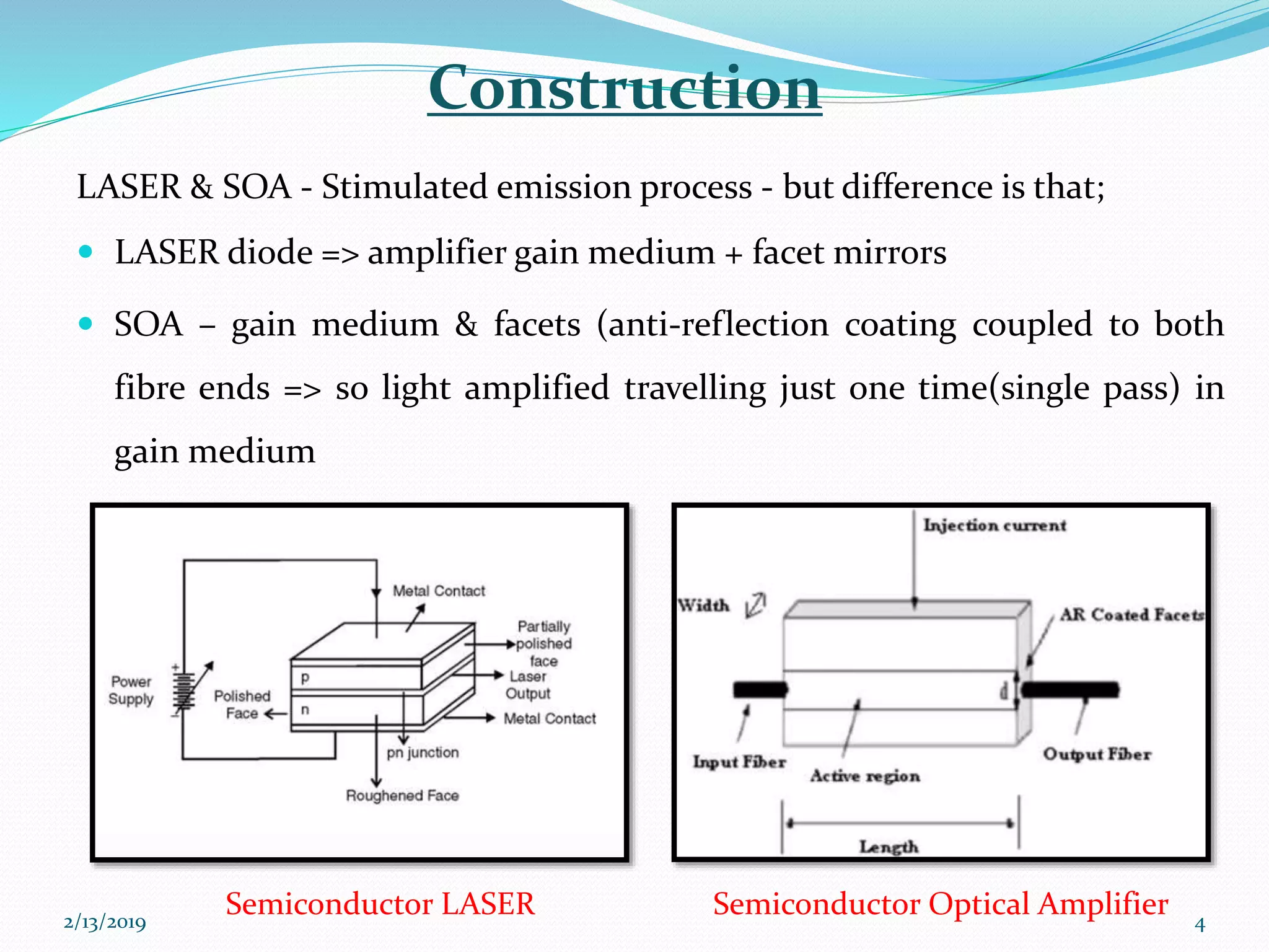
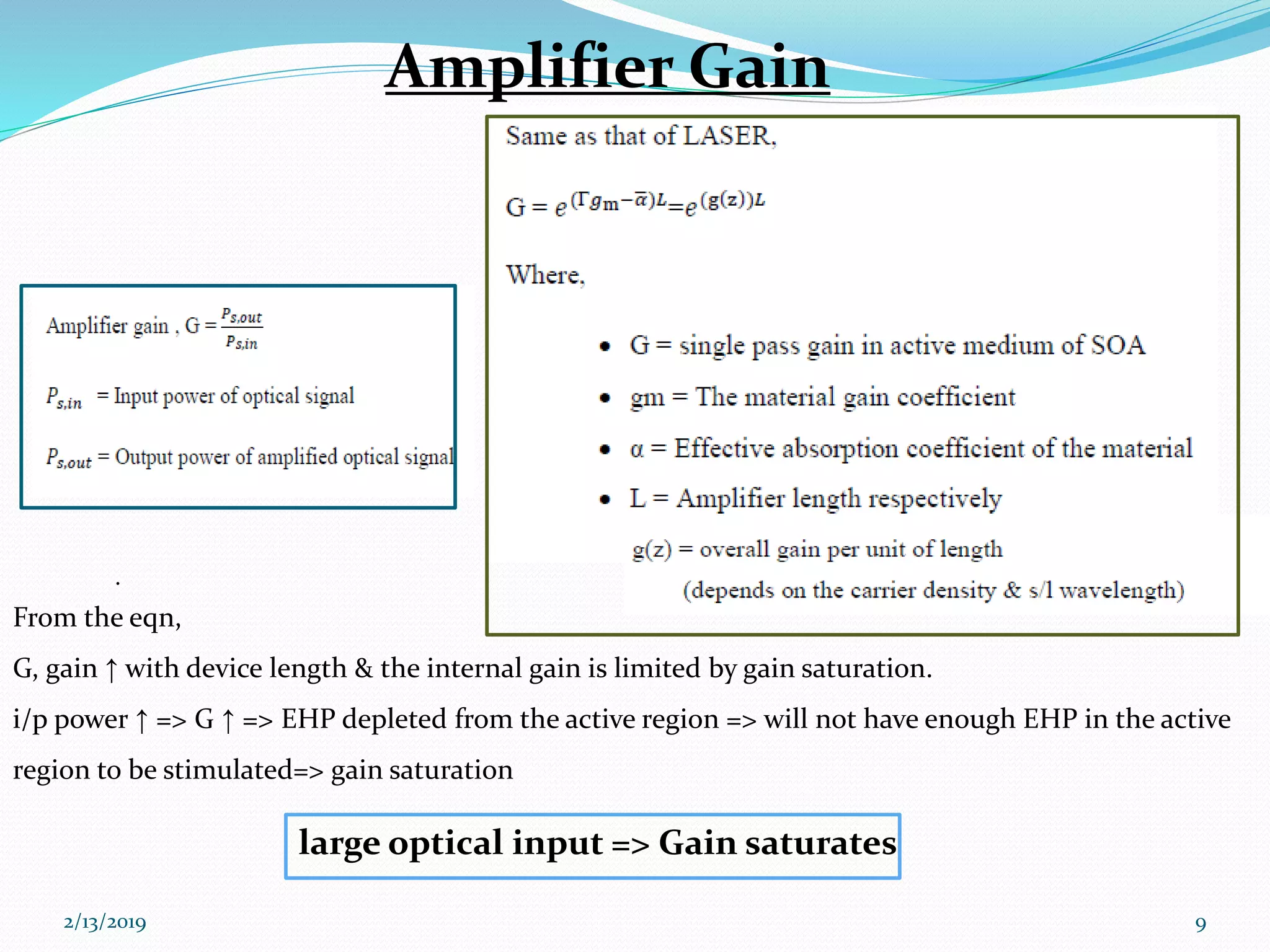
2/13/2019 1
Contents
 Optical Amplifier
 Types of SOA
 Semiconductor Optical Amplifier
 External pumping
 Amplifier gain
2/13/2019 2
Optical Amplifier (OA)
 It’s a fibre optic device to amplify optical signals
 Principle of OA – Stimulated emission
2/13/2019 3
 LASER diode => amplifier gain medium + facet mirrors
 SOA – gain medium & facets (anti-reflection coating coupled to both
fibre ends => so light amplified travelling just one time(single pass) in
gain medium
2/13/2019 4
LASER & SOA - Stimulated emission process - but difference is that;
Construction
Semiconductor Optical AmplifierSemiconductor LASER
Types:
Fabry-Perot amplifiers (FPA)
• When the light enters, it gets amplified as
it reflects back and forth between the
mirrors until emitted at a higher intensity.
• It is sensitive to temperature and input
optical frequency.
Traveling-wave amplifiers (TWA)
• It is the same as FPA except that the end facets are either antireflection coated
or cleaved at an angle so that internal reflection does not take place and the input
signal gets amplified only once during a single pass through the device. They
widely used because they have a large optical bandwidth low polarization
sensitivity.
2/13/2019 5
 Substrate = InP
 Core (active region = InGaAsP) =>smaller Eg=> smaller R.I
 Cladding => p-doped and n- doped quasi-neutral regions => wider band gap
 During operation as an optical amplifier, light is coupled into the waveguide at z =0. As
the light propagates inside the waveguide it gets amplified. Finally, when light comes out
at z = L, its power is much higher compared to what it was at z=0.
Fig: double hetero structure configuration AInGaAsP/InP2/13/2019 6
cladding
core
Substrate
Current injection into core
SiO2
dielectric
insulating
layer
SOA
2/13/2019 7
External Pumping
external pumping rate
combined time constant
coming from spontaneous-
carrier recombination
mechanism
current density
charge carrier
stimulated emission
thickness of active area
optical confinement factor
gain constant
group velocity photon density
overall gain per unit of length
threshold carrier density
energy of photon
power of optical signal
width of active
area
carrier density in excited stateRate equation
Current injection -> ext. pumping => to
amplify optical signals via stimulated
emission=> PI
Gain is increased with increasing current injection
Gain is saturated with increasing photon density
2/13/2019 8
.
From the eqn,
G, gain ↑ with device length & the internal gain is limited by gain saturation.
i/p power ↑ => G ↑ => EHP depleted from the active region => will not have enough EHP in the active
region to be stimulated=> gain saturation
2/13/2019 9
Amplifier Gain
large optical input => Gain saturates
2/13/2019 10
2/13/2019 11
2/13/2019 12
2/13/2019 13
2/13/2019 14
- From fig, G depended on the optical input power
- Here G is reduced by 3dB from unsaturated amplifier gain (G0)
fig: single pass gain vs input power
Linear region
Non- Linear region
Main characteristics
 They are polarization dependent
 They have relatively high gain (20 dB).
 Their output saturation power is in the range of 5-10 dBm.
 They have a large bandwidth.
 They operate at the wavelength regions of 1300 and 1500nm.
 They are compact semiconductors easily integrable with other devices, which can also
be used as wavelength converter.
 Because of nonlinear phenomena, have a high noise figure and high cross-talk level
 Technological difficulties in fabricating SOAs with low (up to 10-4) reflectance’s.
2/13/2019 15
Reference
 Optical Fiber Communications by: G. Keiser; 5th edition
2/13/2019 16
Thank you
2/13/2019 17

Semiconductor Optical Amplifier

  • 1.
  • 2.
    Contents  Optical Amplifier Types of SOA  Semiconductor Optical Amplifier  External pumping  Amplifier gain 2/13/2019 2
  • 3.
    Optical Amplifier (OA) It’s a fibre optic device to amplify optical signals  Principle of OA – Stimulated emission 2/13/2019 3
  • 4.
     LASER diode=> amplifier gain medium + facet mirrors  SOA – gain medium & facets (anti-reflection coating coupled to both fibre ends => so light amplified travelling just one time(single pass) in gain medium 2/13/2019 4 LASER & SOA - Stimulated emission process - but difference is that; Construction Semiconductor Optical AmplifierSemiconductor LASER
  • 5.
    Types: Fabry-Perot amplifiers (FPA) •When the light enters, it gets amplified as it reflects back and forth between the mirrors until emitted at a higher intensity. • It is sensitive to temperature and input optical frequency. Traveling-wave amplifiers (TWA) • It is the same as FPA except that the end facets are either antireflection coated or cleaved at an angle so that internal reflection does not take place and the input signal gets amplified only once during a single pass through the device. They widely used because they have a large optical bandwidth low polarization sensitivity. 2/13/2019 5
  • 6.
     Substrate =InP  Core (active region = InGaAsP) =>smaller Eg=> smaller R.I  Cladding => p-doped and n- doped quasi-neutral regions => wider band gap  During operation as an optical amplifier, light is coupled into the waveguide at z =0. As the light propagates inside the waveguide it gets amplified. Finally, when light comes out at z = L, its power is much higher compared to what it was at z=0. Fig: double hetero structure configuration AInGaAsP/InP2/13/2019 6 cladding core Substrate Current injection into core SiO2 dielectric insulating layer SOA
  • 7.
    2/13/2019 7 External Pumping externalpumping rate combined time constant coming from spontaneous- carrier recombination mechanism current density charge carrier stimulated emission thickness of active area optical confinement factor gain constant group velocity photon density overall gain per unit of length threshold carrier density energy of photon power of optical signal width of active area carrier density in excited stateRate equation Current injection -> ext. pumping => to amplify optical signals via stimulated emission=> PI
  • 8.
    Gain is increasedwith increasing current injection Gain is saturated with increasing photon density 2/13/2019 8
  • 9.
    . From the eqn, G,gain ↑ with device length & the internal gain is limited by gain saturation. i/p power ↑ => G ↑ => EHP depleted from the active region => will not have enough EHP in the active region to be stimulated=> gain saturation 2/13/2019 9 Amplifier Gain large optical input => Gain saturates
  • 10.
  • 11.
  • 12.
  • 13.
  • 14.
    2/13/2019 14 - Fromfig, G depended on the optical input power - Here G is reduced by 3dB from unsaturated amplifier gain (G0) fig: single pass gain vs input power Linear region Non- Linear region
  • 15.
    Main characteristics  Theyare polarization dependent  They have relatively high gain (20 dB).  Their output saturation power is in the range of 5-10 dBm.  They have a large bandwidth.  They operate at the wavelength regions of 1300 and 1500nm.  They are compact semiconductors easily integrable with other devices, which can also be used as wavelength converter.  Because of nonlinear phenomena, have a high noise figure and high cross-talk level  Technological difficulties in fabricating SOAs with low (up to 10-4) reflectance’s. 2/13/2019 15
  • 16.
    Reference  Optical FiberCommunications by: G. Keiser; 5th edition 2/13/2019 16
  • 17.