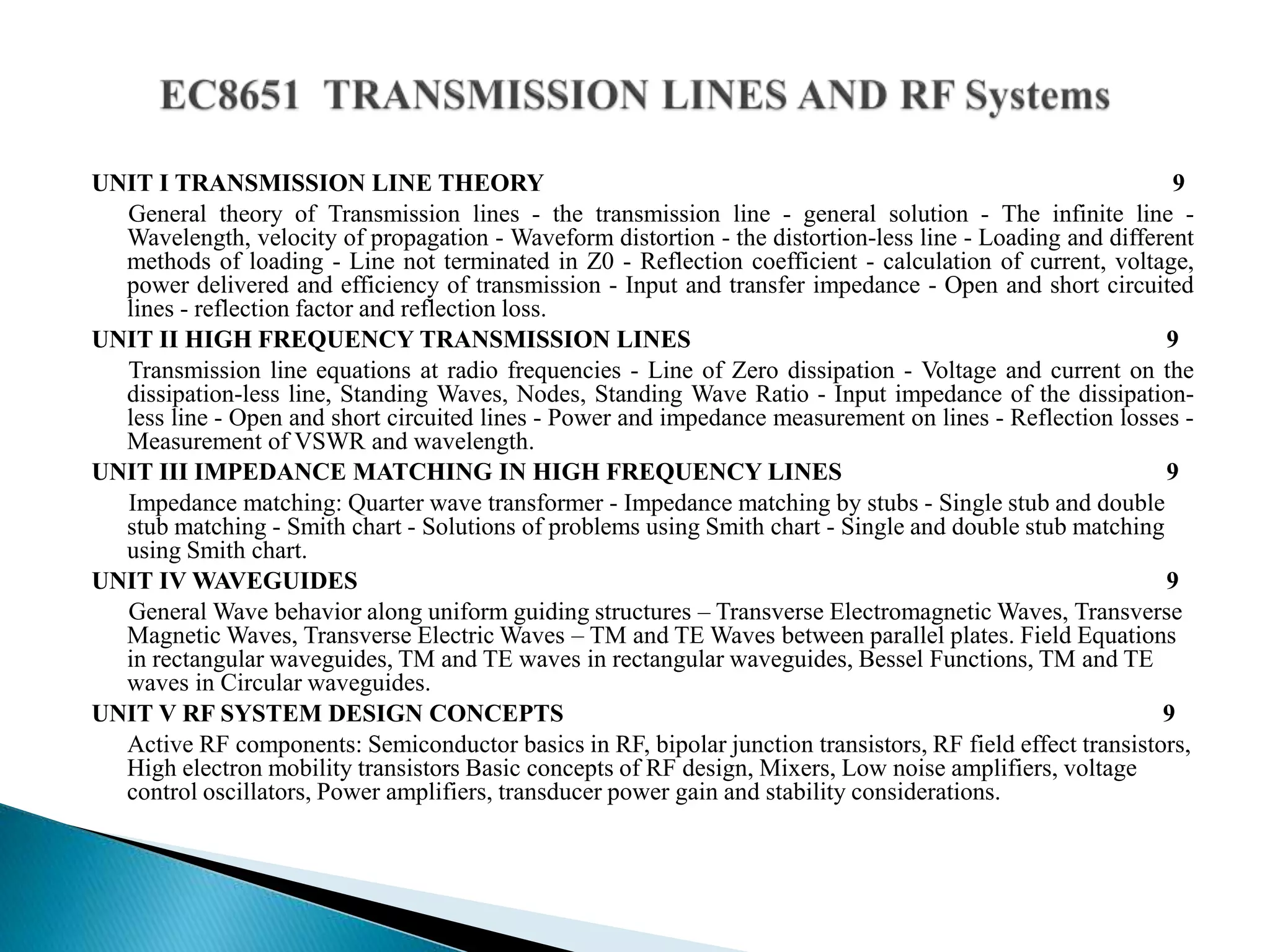
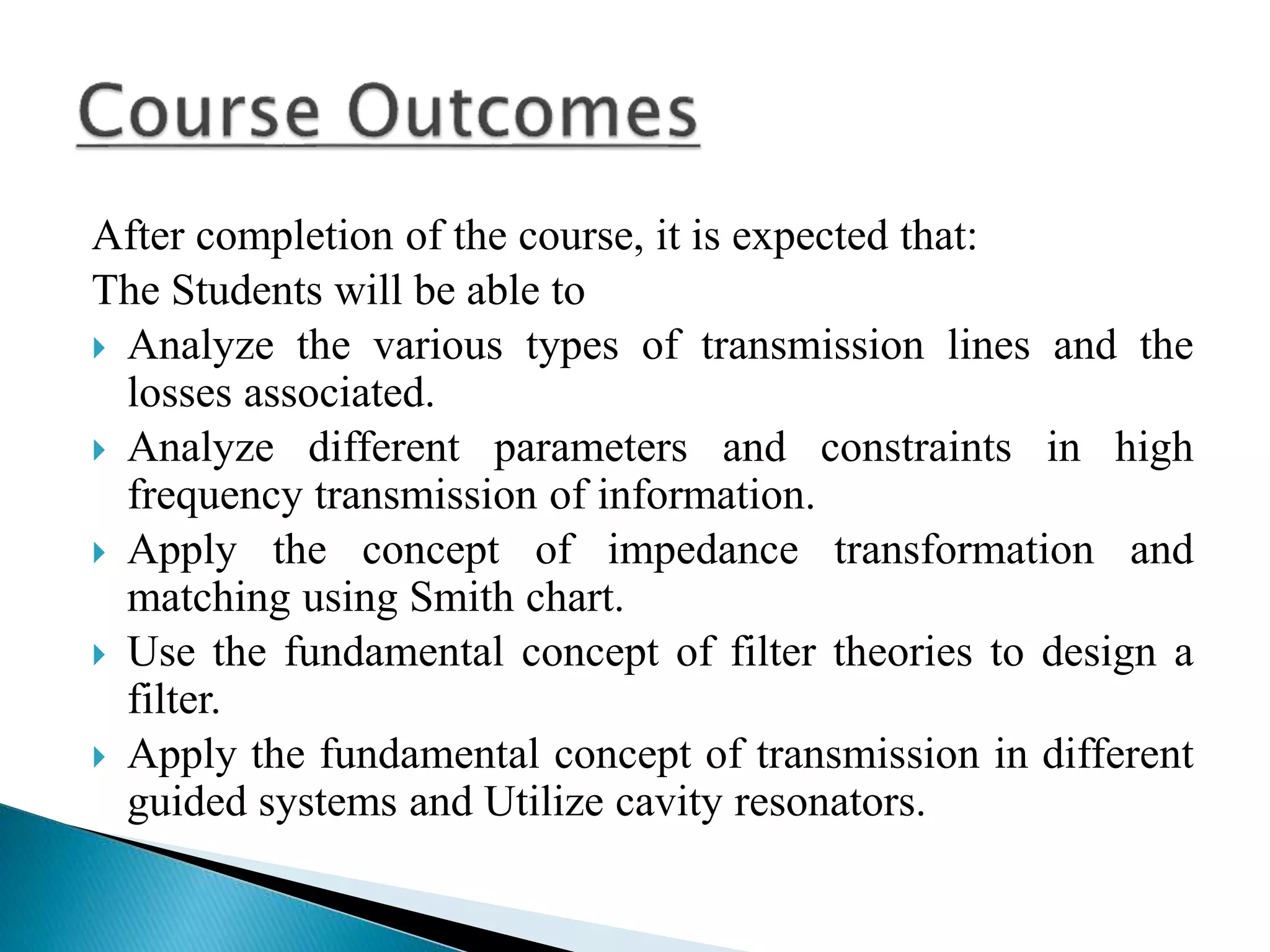
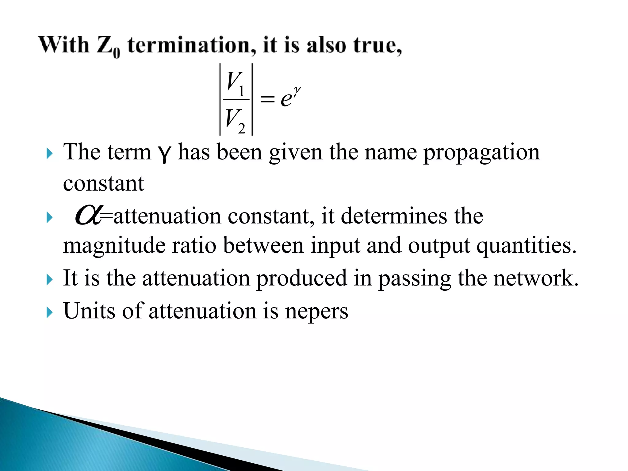
D.Gopinath AP/ECE
Ramco Institute of technology
Academic year (2019-20 Even)
UNIT I TRANSMISSION LINE THEORY 9
General theory of Transmission lines - the transmission line - general solution - The infinite line -
Wavelength, velocity of propagation - Waveform distortion - the distortion-less line - Loading and different
methods of loading - Line not terminated in Z0 - Reflection coefficient - calculation of current, voltage,
power delivered and efficiency of transmission - Input and transfer impedance - Open and short circuited
lines - reflection factor and reflection loss.
UNIT II HIGH FREQUENCY TRANSMISSION LINES 9
Transmission line equations at radio frequencies - Line of Zero dissipation - Voltage and current on the
dissipation-less line, Standing Waves, Nodes, Standing Wave Ratio - Input impedance of the dissipation-
less line - Open and short circuited lines - Power and impedance measurement on lines - Reflection losses -
Measurement of VSWR and wavelength.
UNIT III IMPEDANCE MATCHING IN HIGH FREQUENCY LINES 9
Impedance matching: Quarter wave transformer - Impedance matching by stubs - Single stub and double
stub matching - Smith chart - Solutions of problems using Smith chart - Single and double stub matching
using Smith chart.
UNIT IV WAVEGUIDES 9
General Wave behavior along uniform guiding structures – Transverse Electromagnetic Waves, Transverse
Magnetic Waves, Transverse Electric Waves – TM and TE Waves between parallel plates. Field Equations
in rectangular waveguides, TM and TE waves in rectangular waveguides, Bessel Functions, TM and TE
waves in Circular waveguides.
UNIT V RF SYSTEM DESIGN CONCEPTS 9
Active RF components: Semiconductor basics in RF, bipolar junction transistors, RF field effect transistors,
High electron mobility transistors Basic concepts of RF design, Mixers, Low noise amplifiers, voltage
control oscillators, Power amplifiers, transducer power gain and stability considerations.
 To enable the students to understand the various types
of transmission lines and gain the knowledge about
losses associated.
 To make the students to understand the principles of
signal propagation of line at high frequencies.
 To enable the students to learn the concept of
impedance matching.
 To make the students to acquire knowledge on filter
theories.
 To enable the students to investigate some properties of
electromagnetic waves in Guided system and
Resonators.
After completion of the course, it is expected that:
The Students will be able to
 Analyze the various types of transmission lines and the
losses associated.
 Analyze different parameters and constraints in high
frequency transmission of information.
 Apply the concept of impedance transformation and
matching using Smith chart.
 Use the fundamental concept of filter theories to design a
filter.
 Apply the fundamental concept of transmission in different
guided systems and Utilize cavity resonators.
UNIT I TRANSMISSION LINE THEORY
General theory of Transmission lines
Transmission Line in communication carry
1)Telephone signals
2)Computer data in LAN
3)TV signals in cable TV network
4)Telegraph signals
5)Antenna to transmitter link
 Characteristic impedance, Zo
◦Ratio of voltage to current, V/I = Z
◦From transmission line model
CjG
LjR
Zo



currentOutput
currentInput
ePerformanc 
If the ratios of voltage to current at input and
output of the network are equal then
2
1
2
1
V
V
I
I

 The magnitude ratio does not express the complete
network performance , the phase angle between the
currents being needed as well.
 The use of exponential can be extended to include the
phasor current ratio.
N
e
I
I
V
V

2
1
2
1
Hence
 j
 j
ee
I
I 

2
1
If  A
I
I
2
1

e
I
I
A 
2
1 
 j
e
 The term γ has been given the name propagation
constant
 =attenuation constant, it determines the
magnitude ratio between input and output quantities.
 It is the attenuation produced in passing the network.
 Units of attenuation is nepers

e
V
V

2
1


TEXT BOOKS:
 John D Ryder, “Networks, lines and fields”, 2nd
Edition, Prentice Hall India, 2015. (UNIT I-IV).
 Mathew M. Radmanesh, “Radio Frequency &Microwave
Electronics”, Pearson Education Asia, Second Edition,
2002. (UNIT V).
REFERENCES:
 Reinhold Ludwig and Powel Bretchko, “RF Circuit
Design – Theory and Applications”, Pearson Education
Asia, First Edition, 2001.
 D. K. Misra, “Radio Frequency and Microwave
Communication Circuits- Analysis and Design”, John
Wiley & Sons, 2004.
 E.C.Jordan and K.G. Balmain, “Electromagnetic Waves
and Radiating Systems”, Prentice Hall of India, 2006.
 G.S.N Raju, "Electromagnetic Field Theory and
Transmission Lines”, Pearson Education, First edition
2005.
Transmission lines and RF systems

Transmission lines and RF systems

  • 1.
    D.Gopinath AP/ECE Ramco Instituteof technology Academic year (2019-20 Even)
  • 2.
    UNIT I TRANSMISSIONLINE THEORY 9 General theory of Transmission lines - the transmission line - general solution - The infinite line - Wavelength, velocity of propagation - Waveform distortion - the distortion-less line - Loading and different methods of loading - Line not terminated in Z0 - Reflection coefficient - calculation of current, voltage, power delivered and efficiency of transmission - Input and transfer impedance - Open and short circuited lines - reflection factor and reflection loss. UNIT II HIGH FREQUENCY TRANSMISSION LINES 9 Transmission line equations at radio frequencies - Line of Zero dissipation - Voltage and current on the dissipation-less line, Standing Waves, Nodes, Standing Wave Ratio - Input impedance of the dissipation- less line - Open and short circuited lines - Power and impedance measurement on lines - Reflection losses - Measurement of VSWR and wavelength. UNIT III IMPEDANCE MATCHING IN HIGH FREQUENCY LINES 9 Impedance matching: Quarter wave transformer - Impedance matching by stubs - Single stub and double stub matching - Smith chart - Solutions of problems using Smith chart - Single and double stub matching using Smith chart. UNIT IV WAVEGUIDES 9 General Wave behavior along uniform guiding structures – Transverse Electromagnetic Waves, Transverse Magnetic Waves, Transverse Electric Waves – TM and TE Waves between parallel plates. Field Equations in rectangular waveguides, TM and TE waves in rectangular waveguides, Bessel Functions, TM and TE waves in Circular waveguides. UNIT V RF SYSTEM DESIGN CONCEPTS 9 Active RF components: Semiconductor basics in RF, bipolar junction transistors, RF field effect transistors, High electron mobility transistors Basic concepts of RF design, Mixers, Low noise amplifiers, voltage control oscillators, Power amplifiers, transducer power gain and stability considerations.
  • 3.
     To enablethe students to understand the various types of transmission lines and gain the knowledge about losses associated.  To make the students to understand the principles of signal propagation of line at high frequencies.  To enable the students to learn the concept of impedance matching.  To make the students to acquire knowledge on filter theories.  To enable the students to investigate some properties of electromagnetic waves in Guided system and Resonators.
  • 4.
    After completion ofthe course, it is expected that: The Students will be able to  Analyze the various types of transmission lines and the losses associated.  Analyze different parameters and constraints in high frequency transmission of information.  Apply the concept of impedance transformation and matching using Smith chart.  Use the fundamental concept of filter theories to design a filter.  Apply the fundamental concept of transmission in different guided systems and Utilize cavity resonators.
  • 5.
    UNIT I TRANSMISSIONLINE THEORY General theory of Transmission lines
  • 8.
    Transmission Line incommunication carry 1)Telephone signals 2)Computer data in LAN 3)TV signals in cable TV network 4)Telegraph signals 5)Antenna to transmitter link
  • 14.
     Characteristic impedance,Zo ◦Ratio of voltage to current, V/I = Z ◦From transmission line model CjG LjR Zo   
  • 15.
    currentOutput currentInput ePerformanc  If theratios of voltage to current at input and output of the network are equal then 2 1 2 1 V V I I 
  • 16.
     The magnituderatio does not express the complete network performance , the phase angle between the currents being needed as well.  The use of exponential can be extended to include the phasor current ratio. N e I I V V  2 1 2 1
  • 17.
    Hence  j  j ee I I  2 1 If  A I I 2 1  e I I A  2 1   j e
  • 18.
     The termγ has been given the name propagation constant  =attenuation constant, it determines the magnitude ratio between input and output quantities.  It is the attenuation produced in passing the network.  Units of attenuation is nepers  e V V  2 1 
  • 19.
  • 20.
    TEXT BOOKS:  JohnD Ryder, “Networks, lines and fields”, 2nd Edition, Prentice Hall India, 2015. (UNIT I-IV).  Mathew M. Radmanesh, “Radio Frequency &Microwave Electronics”, Pearson Education Asia, Second Edition, 2002. (UNIT V). REFERENCES:  Reinhold Ludwig and Powel Bretchko, “RF Circuit Design – Theory and Applications”, Pearson Education Asia, First Edition, 2001.  D. K. Misra, “Radio Frequency and Microwave Communication Circuits- Analysis and Design”, John Wiley & Sons, 2004.  E.C.Jordan and K.G. Balmain, “Electromagnetic Waves and Radiating Systems”, Prentice Hall of India, 2006.  G.S.N Raju, "Electromagnetic Field Theory and Transmission Lines”, Pearson Education, First edition 2005.