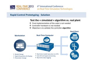
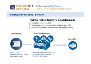
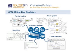
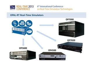
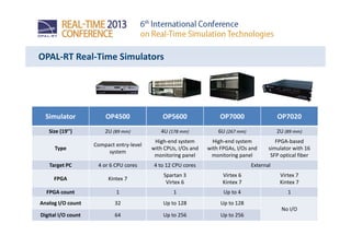
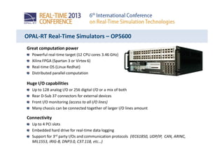
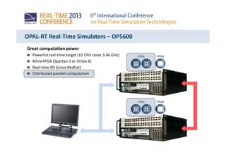
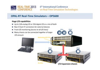
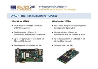
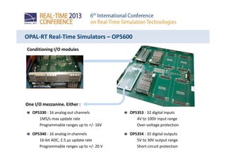
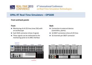
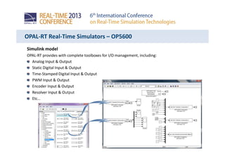
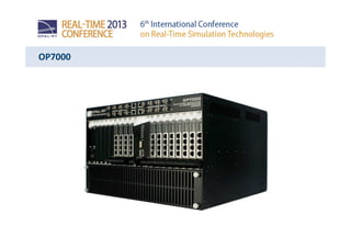
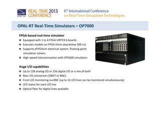
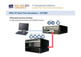
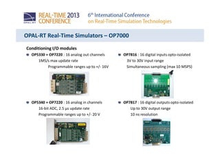
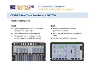
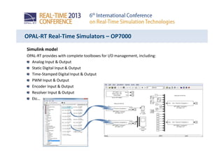
OP5600 & OP7000
High performance Real-Time
simulators
Yahia Bouzid
25th June 2013
Contents
Model-based design concept
Applications
Rapid Control Prototyping
Hardware in-the-loop
OPAL-RT Real-Time simulators
Overview
OP5600
OP7000
Conclusion
Model-Based Design – Designing a controller
Rapid Control PrototypingRapid Control Prototyping Hardware in-the-loop TestingHardware in-the-loop Testing
Desktop SimulationDesktop Simulation
CodingCoding
ValidationValidation
Rapid Control Prototyping - Issues
Controller
Test the controller algorithm vs. real plant
Is the controller code already implemented ?
Do we even have the controller hardware ?
How to validate the algorithm ASAP ?
Real Plant
Rapid Control Prototyping - Solution
Real-time model execution on CPU
Fast I/O and signal processing
Real-time data logging
Real-Time Computer
Model Design
Signal Acquisition & Display
Parameter change
Workstation
Test the « simulated » algorithm vs. real plant
Final implementation of the code is not needed
Controller hardware is not needed
Objective is to validate the controller algorithm
Real Plant
Hardware in-the-loop - Issues
Validate the real controller vs. real plant
Is the plant available ?
Is the validation of controller vs. real plant safe ?
Are all test scenarios feasible with a real plant ?
Real Plant
Controller
Hardware in-the-loop - Solution
Real-time model execution on CPU
Fast I/O and signal processing
Real-time data logging
Real-Time Computer
Model Design
Signal Acquisition & Display
Parameter change
Workstation
Test the real controller vs. simulated plant
Real plant is not needed
Safe validation of integrated controller (HW + SW)
Any scenario can be implemented (faulty behaviour)
Controller
OPAL-RT Real-Time Simulators
Algorithms
Physical models Power systems
Stateflow charts
Code
Real-Time Computer
OPAL-RT Real-Time Simulators
OP7000
OP5600
OP7020
OP4500
OPAL-RT Real-Time Simulators
Simulator OP4500 OP5600 OP7000 OP7020
Size (19’’) 2U (89 mm) 4U (178 mm) 6U (267 mm) 2U (89 mm)
Type
Compact entry-level
system
High-end system
with CPUs, I/Os and
monitoring panel
High-end system
with FPGAs, I/Os and
monitoring panel
FPGA-based
simulator with 16
SFP optical fiber
Target PC 4 or 6 CPU cores 4 to 12 CPU cores External
FPGA Kintex 7
Spartan 3
Virtex 6
Virtex 6
Kintex 7
Virtex 7
Kintex 7
FPGA count 1 1 Up to 4 1
Analog I/O count 32 Up to 128 Up to 128
No I/O
Digital I/O count 64 Up to 256 Up to 256
OPAL-RT Real-Time Simulators
Integrated test bed example
32-core real-time target
OP7000 FPGA-based chassis
2 x OP5600 Expansion chassis
Powerful
Flexible
Scalable
Distributed
OP5600
OPAL-RT Real-Time Simulators – OP5600
Great computation power
Powerful real-time target (12 CPU cores 3.46 GHz)
Xilinx FPGA (Spartan 3 or Virtex 6)
Real-time OS (Linux Redhat)
Distributed parallel computation
Huge I/O capabilities
Up to 128 analog I/O or 256 digital I/O or a mix of both
Rear D-Sub 37 connectors for external devices
Front I/O monitoring (access to all I/O lines)
Many chassis can be connected together of larger I/O lines amount
Connectivity
Up to 4 PCI slots
Embedded hard drive for real-time data logging
Support for 3rd party I/Os and communication protocols (IEC61850, UDP/IP, CAN, ARINC,
MIL1553, IRIG-B, DNP3.0, C37.118, etc…)
Great computation power
Powerful real-time target (12 CPU cores 3.46 GHz)
Xilinx FPGA (Spartan 3 or Virtex 6)
Real-time OS (Linux Redhat)
Distributed parallel computation
OPAL-RT Real-Time Simulators – OP5600
CPUs FPGA
CPUs FPGA
Huge I/O capabilities
Up to 128 analog I/O or 256 digital I/O or a mix of both
Rear D-Sub 37 connectors for external devices
Front I/O monitoring (access to all I/O lines)
Many chassis can be connected together of larger
I/O amount
OPAL-RT Real-Time Simulators – OP5600
CPUs FPGA
Motherboard & CPUs
FPGA FPGA
I/O Expansion chassis
No CPUs
OPAL-RT Real-Time Simulators – OP5600
Xilinx Virtex 6 FPGA
FPGA designed for model calculation
and I/O management
Flexible solution : different IO
combinations with the same FPGA board
Up to 192 digital I/Os or up to 96 16-bit
ADC and DAC channels
Sampling time : 100 MHz or 200 MHz
Xilinx Spartan 3 FPGA
FPGA board designed for I/O management
(analog and/or digital I/Os)
Flexible solution : different IO
combinations with the same FPGA board
Up to 256 digital I/Os or up to 128 16-bit
ADC and DAC channels
Sampling time : 100 MHz
OPAL-RT Real-Time Simulators – OP5600
Conditioning I/O modules
One I/O mezzanine. Either :
OP5353 : 32 digital inputs
4V to 100V input range
Over-voltage protection
OP5354 : 32 digital outputs
5V to 30V output range
Short-circuit protection
OP5330 : 16 analog out channels
1MS/s max update rate
Programmable ranges up to +/- 16V
OP5340 : 16 analog in channels
16-bit ADC, 2.5 µs update rate
Programmable ranges up to +/- 20 V
OPAL-RT Real-Time Simulators – OP5600
Front and back panels
Front
Monitoring of all I/O lines (max 256) with
an oscilloscope
Each RJ45 connector drives 4 signals
These signals can be redirected to the
monitoring panel an its BNC interface
Back
Connection to external devices
(controllers, plants)
16 DB37 connectors drive all I/O lines
16 channels per DB37 connector
OPAL-RT Real-Time Simulators – OP5600
Simulink model
OPAL-RT provides with complete toolboxes for I/O management, including:
Analog Input & Output
Static Digital Input & Output
Time-Stamped Digital Input & Output
PWM Input & Output
Encoder Input & Output
Resolver Input & Output
Etc…
OP7000
OPAL-RT Real-Time Simulators – OP7000
FPGA-based real-time simulator
Equipped with 1 to 4 FPGA VIRTEX 6 boards
Executes models on FPGA (time step below 500 ns)
Supports eFPGAsim electrical system, floating-point
simulation solvers
High-speed interconnection with OP5600 simulators
Huge I/O capabilities
Up to 128 analog I/O or 256 digital I/O or a mix of both
Rear I/O connectors (DB37 or BNC)
Front I/O monitoring via BNC (up to 16 I/O lines can be monitored simultaneously)
LED status for each I/O line
Optical fiber for digital lines available
FPGA-based real-time simulator
High-speed interconnection with OP5600 simulators CPUs FPGA
FPGAFPGAFPGA FPGA
OPAL-RT Real-Time Simulators – OP7000
Conditioning I/O modules
OP5330 + OP7220 : 16 analog out channels
1MS/s max update rate
Programmable ranges up to +/- 16V
OP5340 + OP7220 : 16 analog in channels
16-bit ADC, 2.5 µs update rate
Programmable ranges up to +/- 20 V
OP7816 : 16 digital inputs opto-isolated
3V to 30V input range
Simultaneous sampling (max 10 MSPS)
OP7817 : 16 digital outputs opto-isolated
Up to 30V output range
10 ns resolution
OPAL-RT Real-Time Simulators – OP7000
Front and back panels
Front
Monitoring of all I/Os (max 256) with an
oscilloscope or status LEDs
Each RJ45 connector drives 4 signals
These signals can be redirected to the
monitoring panel an its BNC interface
Back
Connection to external devices
(controllers, plants)
DB37 and BNC connectors drive all I/O
lines
16 channels per DB37 connector
OPAL-RT Real-Time Simulators – OP7000
Simulink model
OPAL-RT provides with complete toolboxes for I/O management, including:
Analog Input & Output
Static Digital Input & Output
Time-Stamped Digital Input & Output
PWM Input & Output
Encoder Input & Output
Resolver Input & Output
Etc…
OPAL-RT Real-Time Simulators
Hardware in-the-loop / Rapid Control Prototyping / Simulation
Huge computation power
Model execution on CPUs and FPGAs
Parallel distributed computation
Fast I/O and signal processing (analog & digital signals)
Flexible and scalable I/Os (thousands of I/O lines)
Front I/O monitoring on oscilloscope
Embedded data logging (MAT-files)
Support for 3rd party devices (I/O & communication boards)
Controlled remotely from the Workstation
Scripting and automatic tests
OPAL-RT Real-Time Simulators
Thank you !
Questions ?

OPAL-RT RT13: OP5600 & OP7000 hardware

  • 1.
    OP5600 & OP7000 Highperformance Real-Time simulators Yahia Bouzid 25th June 2013
  • 2.
    Contents Model-based design concept Applications RapidControl Prototyping Hardware in-the-loop OPAL-RT Real-Time simulators Overview OP5600 OP7000 Conclusion
  • 3.
    Model-Based Design –Designing a controller Rapid Control PrototypingRapid Control Prototyping Hardware in-the-loop TestingHardware in-the-loop Testing Desktop SimulationDesktop Simulation CodingCoding ValidationValidation
  • 4.
    Rapid Control Prototyping- Issues Controller Test the controller algorithm vs. real plant Is the controller code already implemented ? Do we even have the controller hardware ? How to validate the algorithm ASAP ? Real Plant
  • 5.
    Rapid Control Prototyping- Solution Real-time model execution on CPU Fast I/O and signal processing Real-time data logging Real-Time Computer Model Design Signal Acquisition & Display Parameter change Workstation Test the « simulated » algorithm vs. real plant Final implementation of the code is not needed Controller hardware is not needed Objective is to validate the controller algorithm Real Plant
  • 6.
    Hardware in-the-loop -Issues Validate the real controller vs. real plant Is the plant available ? Is the validation of controller vs. real plant safe ? Are all test scenarios feasible with a real plant ? Real Plant Controller
  • 7.
    Hardware in-the-loop -Solution Real-time model execution on CPU Fast I/O and signal processing Real-time data logging Real-Time Computer Model Design Signal Acquisition & Display Parameter change Workstation Test the real controller vs. simulated plant Real plant is not needed Safe validation of integrated controller (HW + SW) Any scenario can be implemented (faulty behaviour) Controller
  • 8.
    OPAL-RT Real-Time Simulators Algorithms Physicalmodels Power systems Stateflow charts Code Real-Time Computer
  • 9.
  • 10.
    OPAL-RT Real-Time Simulators SimulatorOP4500 OP5600 OP7000 OP7020 Size (19’’) 2U (89 mm) 4U (178 mm) 6U (267 mm) 2U (89 mm) Type Compact entry-level system High-end system with CPUs, I/Os and monitoring panel High-end system with FPGAs, I/Os and monitoring panel FPGA-based simulator with 16 SFP optical fiber Target PC 4 or 6 CPU cores 4 to 12 CPU cores External FPGA Kintex 7 Spartan 3 Virtex 6 Virtex 6 Kintex 7 Virtex 7 Kintex 7 FPGA count 1 1 Up to 4 1 Analog I/O count 32 Up to 128 Up to 128 No I/O Digital I/O count 64 Up to 256 Up to 256
  • 11.
    OPAL-RT Real-Time Simulators Integratedtest bed example 32-core real-time target OP7000 FPGA-based chassis 2 x OP5600 Expansion chassis Powerful Flexible Scalable Distributed
  • 12.
  • 13.
    OPAL-RT Real-Time Simulators– OP5600 Great computation power Powerful real-time target (12 CPU cores 3.46 GHz) Xilinx FPGA (Spartan 3 or Virtex 6) Real-time OS (Linux Redhat) Distributed parallel computation Huge I/O capabilities Up to 128 analog I/O or 256 digital I/O or a mix of both Rear D-Sub 37 connectors for external devices Front I/O monitoring (access to all I/O lines) Many chassis can be connected together of larger I/O lines amount Connectivity Up to 4 PCI slots Embedded hard drive for real-time data logging Support for 3rd party I/Os and communication protocols (IEC61850, UDP/IP, CAN, ARINC, MIL1553, IRIG-B, DNP3.0, C37.118, etc…)
  • 14.
    Great computation power Powerfulreal-time target (12 CPU cores 3.46 GHz) Xilinx FPGA (Spartan 3 or Virtex 6) Real-time OS (Linux Redhat) Distributed parallel computation OPAL-RT Real-Time Simulators – OP5600 CPUs FPGA CPUs FPGA
  • 15.
    Huge I/O capabilities Upto 128 analog I/O or 256 digital I/O or a mix of both Rear D-Sub 37 connectors for external devices Front I/O monitoring (access to all I/O lines) Many chassis can be connected together of larger I/O amount OPAL-RT Real-Time Simulators – OP5600 CPUs FPGA Motherboard & CPUs FPGA FPGA I/O Expansion chassis No CPUs
  • 16.
    OPAL-RT Real-Time Simulators– OP5600 Xilinx Virtex 6 FPGA FPGA designed for model calculation and I/O management Flexible solution : different IO combinations with the same FPGA board Up to 192 digital I/Os or up to 96 16-bit ADC and DAC channels Sampling time : 100 MHz or 200 MHz Xilinx Spartan 3 FPGA FPGA board designed for I/O management (analog and/or digital I/Os) Flexible solution : different IO combinations with the same FPGA board Up to 256 digital I/Os or up to 128 16-bit ADC and DAC channels Sampling time : 100 MHz
  • 17.
    OPAL-RT Real-Time Simulators– OP5600 Conditioning I/O modules One I/O mezzanine. Either : OP5353 : 32 digital inputs 4V to 100V input range Over-voltage protection OP5354 : 32 digital outputs 5V to 30V output range Short-circuit protection OP5330 : 16 analog out channels 1MS/s max update rate Programmable ranges up to +/- 16V OP5340 : 16 analog in channels 16-bit ADC, 2.5 µs update rate Programmable ranges up to +/- 20 V
  • 18.
    OPAL-RT Real-Time Simulators– OP5600 Front and back panels Front Monitoring of all I/O lines (max 256) with an oscilloscope Each RJ45 connector drives 4 signals These signals can be redirected to the monitoring panel an its BNC interface Back Connection to external devices (controllers, plants) 16 DB37 connectors drive all I/O lines 16 channels per DB37 connector
  • 19.
    OPAL-RT Real-Time Simulators– OP5600 Simulink model OPAL-RT provides with complete toolboxes for I/O management, including: Analog Input & Output Static Digital Input & Output Time-Stamped Digital Input & Output PWM Input & Output Encoder Input & Output Resolver Input & Output Etc…
  • 20.
  • 21.
    OPAL-RT Real-Time Simulators– OP7000 FPGA-based real-time simulator Equipped with 1 to 4 FPGA VIRTEX 6 boards Executes models on FPGA (time step below 500 ns) Supports eFPGAsim electrical system, floating-point simulation solvers High-speed interconnection with OP5600 simulators Huge I/O capabilities Up to 128 analog I/O or 256 digital I/O or a mix of both Rear I/O connectors (DB37 or BNC) Front I/O monitoring via BNC (up to 16 I/O lines can be monitored simultaneously) LED status for each I/O line Optical fiber for digital lines available
  • 22.
    FPGA-based real-time simulator High-speedinterconnection with OP5600 simulators CPUs FPGA FPGAFPGAFPGA FPGA OPAL-RT Real-Time Simulators – OP7000
  • 23.
    OPAL-RT Real-Time Simulators– OP7000 Conditioning I/O modules OP5330 + OP7220 : 16 analog out channels 1MS/s max update rate Programmable ranges up to +/- 16V OP5340 + OP7220 : 16 analog in channels 16-bit ADC, 2.5 µs update rate Programmable ranges up to +/- 20 V OP7816 : 16 digital inputs opto-isolated 3V to 30V input range Simultaneous sampling (max 10 MSPS) OP7817 : 16 digital outputs opto-isolated Up to 30V output range 10 ns resolution
  • 24.
    OPAL-RT Real-Time Simulators– OP7000 Front and back panels Front Monitoring of all I/Os (max 256) with an oscilloscope or status LEDs Each RJ45 connector drives 4 signals These signals can be redirected to the monitoring panel an its BNC interface Back Connection to external devices (controllers, plants) DB37 and BNC connectors drive all I/O lines 16 channels per DB37 connector
  • 25.
    OPAL-RT Real-Time Simulators– OP7000 Simulink model OPAL-RT provides with complete toolboxes for I/O management, including: Analog Input & Output Static Digital Input & Output Time-Stamped Digital Input & Output PWM Input & Output Encoder Input & Output Resolver Input & Output Etc…
  • 26.
    OPAL-RT Real-Time Simulators Hardwarein-the-loop / Rapid Control Prototyping / Simulation Huge computation power Model execution on CPUs and FPGAs Parallel distributed computation Fast I/O and signal processing (analog & digital signals) Flexible and scalable I/Os (thousands of I/O lines) Front I/O monitoring on oscilloscope Embedded data logging (MAT-files) Support for 3rd party devices (I/O & communication boards) Controlled remotely from the Workstation Scripting and automatic tests
  • 27.