Downloaded 52 times


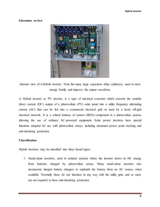
![Hybrid inverter
10
2. Grid-tie inverters, which match phase with a utility-supplied sine wave. Grid-tie inverters
are designed to shut down automatically upon loss of utility supply, for safety reasons.
They do not provide backup power during utility outages.
3. Battery backup inverters, are special inverters which are designed to draw energy from a
battery, manage the battery charge via an onboard charger, and export excess energy to
the utility grid. These inverters are capable of supplying AC energy to selected loads
during a utility outage, and are required to have anti-islanding protection.[clarification needed]
Maximum power point tracking
Hybrid inverters use maximum power point tracking (MPPT) to get the maximum possible
power from the PV array.[3] Solar cells have a complex relationship between solar irradiation,
temperature and total resistance that produces a non-linear output efficiency known as the I-V
curve. It is the purpose of the MPPT system to sample the output of the cells and determine a
resistance (load) to obtain maximum power for any given environmental conditions.[4]
The fill factor, more commonly known by its abbreviation FF, is a parameter which, in
conjunction with the open circuit voltage (Voc) and short circuit current (Isc) of the panel,
determines the maximum power from a solar cell. Fill factor is defined as the ratio of the
maximum power from the solar cell to the product of Voc and Isc.[5]
There are three main types of MPPT algorithms: perturb-and-observe, incremental conductance
and constant voltage. The first two methods are often referred to as hill climbing methods; they
rely on the curve of power plotted against voltage rising to the left of the maximum power point,
and falling on the right.
Solar micro-inverters](https://image.slidesharecdn.com/hybridinverterprojectreport-200116034552/85/Hybrid-inverter-project-report-10-320.jpg)
![Hybrid inverter
11
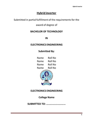
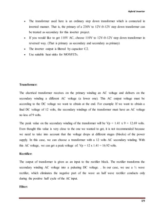
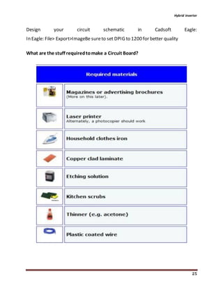
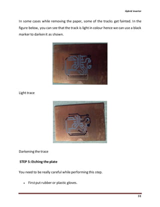
A solar micro-inverter in the process of being installed. The ground wire is attached to the lug
and the panel's DC connections are attached to the cables on the lower right. The AC parallel
trunk cable runs at the top (just visible).
Solar micro-inverter is an inverter designed to operate with a single PV module. The micro-
inverter converts the direct current output from each panel into alternating current. Its design
allows parallel connection of multiple, independent units in a modular way.[8]
Micro-inverter advantages include single panel power optimization, independent operation of
each panel, plug-and play installation, improved installation and fire safety, minimized costs
with system design and stock minimization.
A 2011 study at Appalachian State University reports that individual integrated inverter setup
yielded about 20% more power in unshaded conditions and 27% more power in shaded
conditions compared to string connected setup using one inverter. Both setups used identical
solar panels.
Grid tied Hybrid inverters
Solar grid-tie inverters are designed to quickly disconnect from the grid if the utility grid goes
down. This is an NEC requirement that ensures that in the event of a blackout, the grid tie
inverter will shut down to prevent the energy it produces from harming any line workers who are
sent to fix the power grid.](https://image.slidesharecdn.com/hybridinverterprojectreport-200116034552/85/Hybrid-inverter-project-report-11-320.jpg)
![Hybrid inverter
12
Grid-tie inverters that are available on the market today use a number of different technologies.
The inverters may use the newer high-frequency transformers, conventional low-frequency
transformers, or no transformer. Instead of converting direct current directly to 120 or 240 volts
AC, high-frequency transformers employ a computerized multi-step process that involves
converting the power to high-frequency AC and then back to DC and then to the final AC output
voltage.
Historically, there have been concerns about having transformerless electrical systems feed into
the public utility grid. The concerns stem from the fact that there is a lack of galvanic isolation
between the DC and AC circuits, which could allow the passage of dangerous DC faults to the
AC side.[11] Since 2005, the NFPA's NEC allows transformer-less (or non-galvanically)
inverters. The VDE 0126-1-1 and IEC 6210 also have been amended to allow and define the
safety mechanisms needed for such systems. Primarily, residual or ground current detection is
used to detect possible fault conditions. Also isolation tests are performed to ensure DC to AC
separation.
Many Hybrid inverters are designed to be connected to a utility grid, and will not operate when
they do not detect the presence of the grid. They contain special circuitry to precisely match the
voltage, frequency and phase of the grid.
Solar pumping inverters
Advanced solar pumping inverters convert DC voltage from the solar array into AC voltage to
drive submersible pumps directly without the need for batteries or other energy storage devices.
By utilizing MPPT (maximum power point tracking), solar pumping inverters regulate output
frequency to control the speed of the pumps in order to save the pump motor from damage.
Solar pumping inverters usually have multiple ports to allow the input of DC current generated
by PV arrays, one port to allow the output of AC voltage, and a further port for input from a
water-level sensor.
Market](https://image.slidesharecdn.com/hybridinverterprojectreport-200116034552/85/Hybrid-inverter-project-report-12-320.jpg)
![Hybrid inverter
13
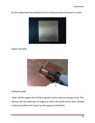
As of 2014, conversion efficiency for state-of-the-art solar converters reached more than 98
percent. While string inverters are used in residential to medium-sized commercial PV systems,
central inverters cover the large commercial and utility-scale market. Market-share for central
and string inverters are about 50 percent and 48 percent, respectively, leaving less than 2 percent
to micro-inverters.[12]
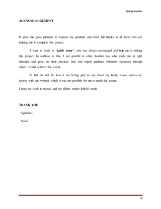
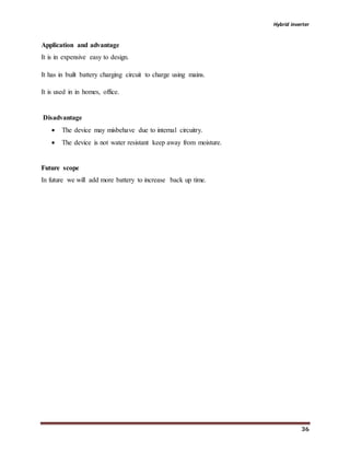
Inverter/converter market in 2014
Type Power Efficiency(a)
Market
share(b)
Remarks
String inverter up to 100 kWp
(c) 98% 50%
Cost(b) €0.15 per watt-peak. Easy to
replace.
Central
inverter
above 100 kWp 98.5% 48%
€0.10 per watt-peak. High reliability.
Often sold along with a service contract.
Micro-inverter
module power
range
90%–95% 1.5%
€0.40 per watt-peak. Ease of replacement
concerns.
DC/DC
converter
Power
optimizer
module power
range
98.8% N/A
€0.40 per watt-peak. Ease of replacement
concerns. Inverter is still needed. About
0.75 GWP installed in 2013.](https://image.slidesharecdn.com/hybridinverterprojectreport-200116034552/85/Hybrid-inverter-project-report-13-320.jpg)


![Hybrid inverter
38
References
1. Gairns J F 1904. Industrial locomotives for mining, factory, and allied uses. Part II.
Compressed air and internal combustion locomotives Cassier's Mag. 16 363-77 8
copyright S-JPSET : ISSN : 2229-7111, Vol. 2, Issue 1 samriddhi, 2011 Study and
Fabrication of Compressed Air Engine .
2. www.tramwayinfo.com/tr amways/Articles/ Compair2.htm accessed 23 June 2009.
3. Bossel U 2005.Thermodynamic Analysis of Compressed Air Vehiclepulsion European
Fuel Cell Forum.
4. Gairns J F 1904. Industrial locomotives for mining, factory, and allied uses. Part II.
Compressed air and internal combustion locomotives Cassirer's Mag.16 363-77. Bossel U
2005.Thermodynamic Analysis of Compressed Air Vehicle Propulsion European Fuel
Cell Forum.
5. "The Air Car". theaircar.com. http://www.the aircar.com/acf/air-cars/the air
car.html.Retrieved 2008-09-12.
6. www.carazoo.com/autonews/0109200801/Tatas-Air- Car--launch-is-Postponed.
7. www.dnaindia.com/money/report_tamo-s-ambitiousair- car-faces-starting-
trouble_1316093.
8. [9] "Advantages of a compressed air as an energy". theaircar.com.
9. www.theaircar.com/acf/air-cars/energy-storage.html. Retrieved 2008-09-16'.](https://image.slidesharecdn.com/hybridinverterprojectreport-200116034552/85/Hybrid-inverter-project-report-38-320.jpg)


The document is a project report on the design and development of a hybrid inverter intended to convert DC to AC power for solar energy applications. It discusses the methodology, components required, and various types of hybrid inverters, as well as their advantages, including efficient energy conversion and battery charging capabilities. The report also covers the importance of renewable energy sources and outlines future scopes for hybrid inverter technology.