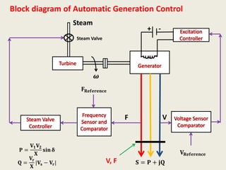
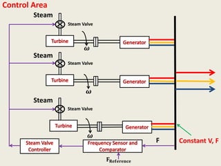
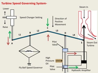
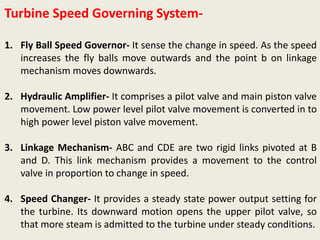
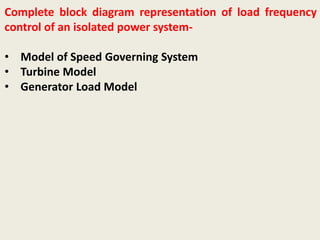
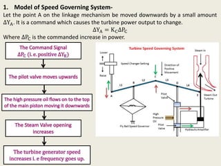
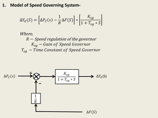
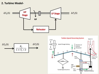
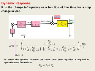
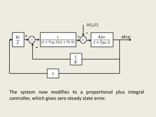
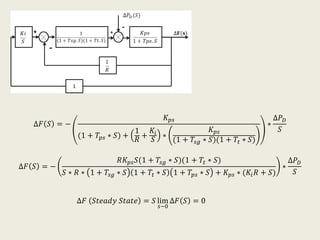
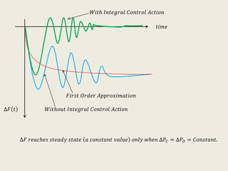
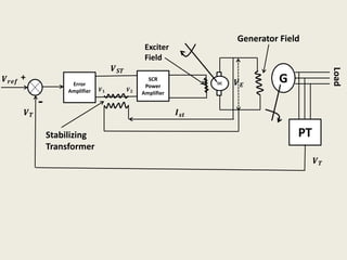
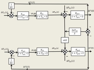
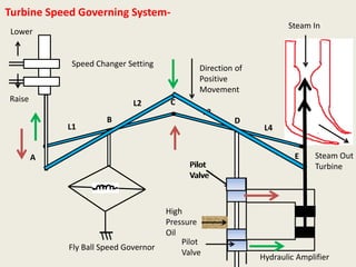
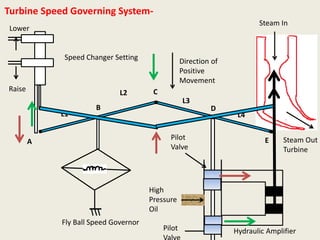
SlideShare a Scribd company logo
DEPARTMENT OF ELECTRICAL ENGINEERING
JSPMS
BHIVARABAISAWANTINSTITUTEOFTECHNOLOGYANDRESEARCH,
WAGHOLI,PUNE
A.Y. 2020-21 (SEM-I)
Class: B.E.
Subject: Power System Operation Control
Unit No-4 Automatic Generation and Control
Prepared by Prof. S. D. Gadekar
Santoshgadekar.919@gmail.com
Mob. No-9130827661
Content
• Introduction
• Concept of Automatic Generation and Control (AGC)
• Block Diagram of AGC
• Turbine Speed Governing System
• Complete block diagram representation of load frequency
control of an isolated power system
• Free Governor Operation
• Numerical on Free Governor Operation
• Dynamics Response
• Proportional Plus Integral Control
• Automatic Voltage Control
• Two area load frequency control
Introduction
𝐏 𝐦 𝐏𝐒
F
For Steady operation or to keep frequency of supply constant
(F=50 Hz).
𝐏 𝐦 = 𝐏𝐒 = 𝐏 𝐑
If 𝐏 𝐌 > 𝐏𝐒 −− −𝐅 𝐢𝐧𝐜𝐫𝐞𝐚𝐬𝐞𝐬
If 𝐏 𝐌 < 𝐏𝐒 −− −𝐅 𝐝𝐞𝐜𝐫𝐞𝐚𝐬𝐞𝐬
𝐏 𝐑
Introduction Continue
𝐐 𝐒 𝐐 𝐑 𝐕 𝐑
For Steady operation the voltages at all buses must be constant
(Voltage at Bus=Rated Value).
𝑬 = 𝑽 𝒔 + 𝑰(𝑹 + 𝒋𝑿 𝒔)
Induced Emf E is called Excitation of Generator and it depends on field
current 𝑰 𝒇 and Power Factor of Generator.
𝐐 𝐒 = 𝐐 𝐑
𝐕 𝐑 − −𝐂𝐨𝐧𝐬𝐭𝐚𝐧𝐭
𝐈 𝐟 𝐄 Power Factor
Introduction
 In modern power system both active power and reactive power demands are
never steady and they continuously changes.
 The mechanical power input must be continuously regulated to match the
active power demand, failing which the machine speed will vary with
consequent change in frequency.
 The permissible maximum change in power frequency in power frequency is
∓0.5 Hz.
 The excitation of generators must be continuously regulated to match the
reactive power demand with reactive generation otherwise the voltages at
various buses may go beyond the prescribed limit.
Block diagram of Automatic Generation Control
+ -
VF
𝐕 𝐑𝐞𝐟𝐞𝐫𝐞𝐧𝐜𝐞
𝐒 = 𝐏 + 𝐣𝐐
𝐅 𝐑𝐞𝐟𝐞𝐫𝐞𝐧𝐜𝐞
𝐏 =
𝐕𝟏 𝐕𝟐
𝐗
𝐬𝐢𝐧 𝛅
𝐐 =
𝐕𝐫
𝐗
|𝐕𝐬 − 𝐕𝐫|
𝝎
Steam
Steam Valve
V, F
Control Area
𝝎
Steam
Steam Valve
𝝎
Steam
Steam Valve
𝝎
Steam
Steam Valve
Constant V, F
𝐅 𝐑𝐞𝐟𝐞𝐫𝐞𝐧𝐜𝐞
F
Control Area-
All generators in an knit electric area constitute a
coherent group so that all the generators speed up and
slow down together maintaining their relative power
angles. Such an area is called as control area.
Turbine Speed Governing System-
Lower
Raise
Speed Changer Setting
Fly Ball Speed Governor
High
Pressure
Oil
A
B
C
D
Pilot
Valve
Pilot
Valve
Direction of
Positive
Movement
E Steam Out
Turbine
Steam In
L1
L2 L3
L4
Hydraulic Amplifier
Turbine Speed Governing System-
1. Fly Ball Speed Governor- It sense the change in speed. As the speed
increases the fly balls move outwards and the point b on linkage
mechanism moves downwards.
2. Hydraulic Amplifier- It comprises a pilot valve and main piston valve
movement. Low power level pilot valve movement is converted in to
high power level piston valve movement.
3. Linkage Mechanism- ABC and CDE are two rigid links pivoted at B
and D. This link mechanism provides a movement to the control
valve in proportion to change in speed.
4. Speed Changer- It provides a steady state power output setting for
the turbine. Its downward motion opens the upper pilot valve, so
that more steam is admitted to the turbine under steady conditions.
Complete block diagram representation of load frequency
control of an isolated power system-
• Model of Speed Governing System
• Turbine Model
• Generator Load Model
1. Model of Speed Governing System-
Let the point A on the linkage mechanism be moved downwards by a small amount
∆YA. It is a command which causes the turbine power output to change.
∆YA = KC∆PC
Where ∆PC is the commanded increase in power.
1. Model of Speed Governing System-
∆𝑌𝐸(𝑆) = ∆𝑃𝐶 𝑠 −
1
𝑅
∆𝐹(𝑆) ∗
𝐾𝑠𝑔
1 + 𝑇𝑠𝑔 ∗ 𝑆
Where,
𝑅 − Speed regulation of the governor
𝐾𝑠𝑔 − 𝐺𝑎𝑖𝑛 𝑜𝑓 𝑆𝑝𝑒𝑒𝑑 𝐺𝑜𝑣𝑒𝑟𝑛𝑜𝑟
𝑇𝑠𝑔 − 𝑇𝑖𝑚𝑒 𝐶𝑜𝑛𝑠𝑡𝑎𝑛𝑡 𝑜𝑓 𝑆𝑝𝑒𝑒𝑑 𝐺𝑜𝑣𝑒𝑟𝑛𝑜𝑟
𝐾𝑠𝑔
1 + 𝑇𝑠𝑔 ∗ 𝑆
∆𝑃𝐶 𝑠
1
𝑅
∆𝑌𝐸(S)
∆𝐹(𝑆)
+
_
2. Turbine Model-
𝝎
∆𝑌𝐸(S) ∆𝑃𝑡(S)
𝐾𝑡
1 + 𝑇𝑡 ∗ 𝑆
∆𝑌𝐸(S) ∆𝑃𝑡(S)
2. Generator Load Model-
The increment in power input to the generator load system is,
∆𝑷 𝑮 − ∆𝑷 𝑫
Where ∆𝑷 𝑮 = ∆𝑷 𝒕 is the incremental turbine power output and ∆𝑷 𝑫 is the
load increment.
The increment in power input to the system is accounted for,
• Rate of increase of stored kinetic energy in the generator rotor.
• The loads sensitive to change in speed such as motor are changes.
+ -
𝝎
∆𝑷 𝒕
∆𝑷 𝑮
∆𝑷 𝑫V, F
2. Generator Load Model-
∆𝐹 𝑆 = ∆𝑃𝐺 𝑆 − ∆𝑃 𝐷(𝑆) ∗
𝐾 𝑝𝑠
1 + 𝑇𝑝𝑠 ∗ 𝑆
Where,
𝐾 𝑝𝑠 − 𝐺𝑎𝑖𝑛 𝑜𝑓 𝑝𝑜𝑤𝑒𝑟 𝑠𝑦𝑠𝑡𝑒𝑚
𝑇𝑝𝑠 − 𝑇𝑖𝑚𝑒 𝐶𝑜𝑛𝑠𝑡𝑎𝑛𝑡 𝑜𝑓 power system
𝐾 𝑝𝑠
1 + 𝑇𝑝𝑠 ∗ 𝑆
∆𝑃𝑡 𝑠 = ∆𝑃𝐺 𝑠
∆𝐹(S)
+
_
∆𝑃 𝐷 𝑠
Complete block diagram representation of load frequency
control of an isolated power system-
𝐾𝑠𝑔
1 + 𝑇𝑠𝑔 ∗ 𝑆
∆𝑃𝐶 𝑠
1
𝑅
∆𝑌𝐸(S)
∆𝐹(𝑆)
+
_
𝐾𝑡
1 + 𝑇𝑡 ∗ 𝑆
∆𝑌𝐸(S) ∆𝑃𝑡(S)
𝐾 𝑝𝑠
1 + 𝑇𝑝𝑠 ∗ 𝑆
∆𝐹(S)
+
_
∆𝑃 𝐷 𝑠
Model of Speed Governing
System
Turbine Model
Generator Load Model
∆𝑷 𝒕 𝒔 = ∆𝑷 𝑮 𝒔
Complete block diagram representation of load frequency
control of an isolated power system-
𝐾𝑠𝑔
1 + 𝑇𝑠𝑔 ∗ 𝑆
∆𝑃𝐶 𝑠
1
𝑅
∆𝐹(𝑆)
+
_
𝐾𝑡
1 + 𝑇𝑡 ∗ 𝑆
∆𝒀 𝑬(S) 𝐾 𝑝𝑠
1 + 𝑇𝑝𝑠 ∗ 𝑆
∆𝐹(S)
+
_
∆𝑃 𝐷 𝑠
∆𝑷𝒕 𝒔 = ∆𝑷 𝑮 𝒔
Consider the speed Changer has fixed settings ∆𝑃𝐶 𝑠 = 0 and load demand
changes.
This operation is known as free governor operation.
Sudden change in load demand by an amount ∆𝑃 𝐷 (For Unit Step Input Function)
is given as,
∆𝑃 𝐷 𝑠 =
∆𝑃 𝐷
𝑆
Continue….
A
B
X 𝑠 + 𝑌 𝑠
𝑻 𝒔 =
𝒀(𝑺)
𝑿(𝑺)
=
𝑨
𝟏 + 𝑨𝑩
∆𝐹 𝑆
−∆𝑃 𝐷 𝑠
=
𝐾 𝑝𝑠
1 + 𝑇𝑝𝑠 ∗ 𝑆
1 +
𝐾 𝑝𝑠
1 + 𝑇𝑝𝑠 ∗ 𝑆
∗
𝐾𝑡
1 + 𝑇𝑡 ∗ 𝑆
∗
𝐾𝑠𝑔
1 + 𝑇𝑠𝑔 ∗ 𝑆
∗
1
𝑅
∆𝑷 𝑪 𝒔 = 𝟎
-
Continue…
∆𝐹 𝑆 = −
𝐾 𝑝𝑠
1 + 𝑇𝑝𝑠 ∗ 𝑆
1 +
𝐾 𝑝𝑠
1 + 𝑇𝑝𝑠 ∗ 𝑆
∗
𝐾𝑡
1 + 𝑇𝑡 ∗ 𝑆
∗
𝐾𝑠𝑔
1 + 𝑇𝑠𝑔 ∗ 𝑆
∗
1
𝑅
∗ ∆𝑃 𝐷 𝑠
∆𝑷 𝑪 𝒔 = 𝟎
∆𝑃 𝐷 𝑠 =
∆𝑃 𝐷
𝑆
∆𝐹 𝑆 = −
𝐾 𝑝𝑠
1 + 𝑇𝑝𝑠 ∗ 𝑆
1 +
𝐾 𝑝𝑠
1 + 𝑇𝑝𝑠 ∗ 𝑆
∗
𝐾𝑡
1 + 𝑇𝑡 ∗ 𝑆
∗
𝐾𝑠𝑔
1 + 𝑇𝑠𝑔 ∗ 𝑆
∗
1
𝑅
∗
∆𝑃 𝐷
𝑆
∆𝑷 𝑪 𝒔 = 𝟎
∆𝑭 = −
𝑲 𝒑𝒔
𝟏 +
𝑲 𝒔𝒈 ∗ 𝑲 𝒕 ∗ 𝑲 𝒑𝒔
𝑹
∗ ∆𝑷 𝑫
∆𝑷 𝑪 𝒔 = 𝟎
At steady state , ∆𝑷 𝑪 𝒔 = 𝟎
∆𝑭 = 𝒔 ∗ lim
𝑺−𝟎
∆𝑭 𝑺
𝐾𝑠𝑔 ∗ 𝐾𝑡 ≅ 1 and 𝐾 𝑝𝑠 =
1
𝐵
Continue…
∆𝑭 = −
𝟏
𝑩 +
𝟏
𝑹
∗ ∆𝑷 𝑫
This equation gives the steady state changes in frequency caused by changes in
load demand.
Frequency in
Percentage
Percentage
Load
Droop
Characteristic
100%
50%
−
𝟏
𝑩 +
𝟏
𝑹
≅
𝟏
𝑹
Continue…
Consider now the steady effect of changing speed changer setting ∆𝑃𝐶 𝑠 =
∆𝑃 𝐶
𝑆
with load demand remaining fixed ∆𝑃 𝐷 𝑠 = 0.
A
B
X 𝑠 + 𝑌 𝑠
𝑻 𝒔 =
𝒀(𝑺)
𝑿(𝑺)
=
𝑨
𝟏 + 𝑨𝑩-
∆𝑭 =
𝟏
𝑩 +
𝟏
𝑹
∗ ∆𝑷 𝑪
If the speed changer setting is changed by ∆𝑃𝐶, while the load demand changes by ∆𝑃 𝐷,
the steady frequency change is
∆𝑭 =
𝟏
𝑩+
𝟏
𝑹
∗ (∆𝑷 𝑪 − ∆𝑃 𝐷)
Numerical-1
A 100 MVA Synchronous generator operates on full load at a frequency of 50 Hz.
The load is suddenly reduced to 50 Mw. Due to time lag in governor system the
steam valve begins to close after 0.4 seconds. Determine the change in frequency
that occurs in this time. (H=5 kWs/kVA of generator capacity)
𝑲𝒊𝒏𝒆𝒕𝒊𝒄 𝑬𝒏𝒆𝒓𝒈𝒚 𝑺𝒕𝒐𝒓𝒆𝒅 𝒊𝒏 𝒓𝒐𝒕𝒂𝒕𝒊𝒏𝒈 𝒑𝒂𝒓𝒕𝒔 𝒐𝒇 𝒈𝒆𝒏𝒆𝒓𝒂𝒕𝒐𝒓 𝒂𝒏𝒅 𝒕𝒖𝒓𝒃𝒊𝒏𝒆 =H*Rating of Machine in kVA
= 𝟓 ∗ 𝟏𝟎𝟎 ∗ 𝟏𝟎𝟎𝟎
= 𝟓 ∗ 𝟏𝟎 𝟓 𝒌𝑾𝒔
Solution -------
𝑬𝒙𝒄𝒆𝒔𝒔 𝑬𝒏𝒆𝒓𝒈𝒚 𝒊𝒏𝒑𝒖𝒕 𝒕𝒐 𝒓𝒐𝒕𝒂𝒕𝒊𝒏𝒈 𝒑𝒂𝒓𝒕𝒔 𝟎. 𝟒 𝑺𝒆𝒄𝒐𝒏𝒅𝒔 = 𝟓𝟎 𝑴𝑾 ∗ 𝟎. 𝟒
= 𝟓𝟎 ∗ 𝟏𝟎𝟎𝟎 ∗ 𝟎. 𝟒
= 𝟐 ∗ 𝟏𝟎 𝟓 𝒌𝑾𝒔
𝑆𝑡𝑜𝑟𝑒𝑑 𝐾𝑖𝑛𝑒𝑡𝑖𝑐 𝐸𝑛𝑒𝑟𝑔𝑦 ∝ 𝐹𝑟𝑒𝑞𝑢𝑒𝑛𝑐𝑦 2
50000 ∝ 502
(50000 + 20000) ∝ 𝐹2
2
𝐹2 = 50 ∗
50000 + 20000
50000
𝑭 𝟐 = 𝟓𝟏 𝑯𝒛
Numerical-2
Two Generators rated 200 MW and 400 MW are operating in parallel. The droop
characteristics of their governors are 4% and 5%, respectively from no load to full
load. Assuming that the generators are operating at 50 Hz at no load, how would a
load of 600 MW be shared between them? What will be the system frequency at this
load? Assume free governor operation. Repeat the problem if both governor s have a
droop of 4%.
∆𝑭 = 𝑫𝑹𝑶𝑶𝑷 × ∆𝑷 𝑫
Solution -------
𝑺𝒊𝒏𝒄𝒆 𝒕𝒉𝒆 𝒈𝒆𝒏𝒆𝒓𝒂𝒕𝒐𝒓𝒔 𝒂𝒓𝒆 𝒊𝒏 𝒑𝒂𝒓𝒂𝒍𝒍𝒆𝒍,
𝒕𝒉𝒆𝒚 𝒘𝒊𝒍𝒍 𝒐𝒑𝒆𝒓𝒂𝒕𝒆 𝒂𝒕 𝒕𝒉𝒆 𝒔𝒂𝒎𝒆 𝒇𝒓𝒆𝒒𝒖𝒆𝒏𝒄𝒚 𝒂𝒕 𝒔𝒕𝒆𝒂𝒅𝒚 𝒍𝒐𝒂𝒅.
𝐿𝑒𝑡 𝐿𝑜𝑎𝑑 𝑜𝑛 𝐺𝑒𝑛𝑒𝑟𝑎𝑡𝑜𝑟 1 200 𝑀𝑊 = 𝑥 𝑀𝑊
𝐹
50
= 0.04 ×
𝑥
200
… … . . 1
𝐿𝑒𝑡 𝐿𝑜𝑎𝑑 𝑜𝑛 𝐺𝑒𝑛𝑒𝑟𝑎𝑡𝑜𝑟 2 400 𝑀𝑊 = (600 − 𝑥) 𝑀𝑊
𝐹
50
= 0.05 ×
(600 − 𝑥)
400
… … . . 2
𝐿𝑜𝑎𝑑 𝑜𝑛 𝐺𝑒𝑛𝑒𝑟𝑎𝑡𝑜𝑟 1 200 𝑀𝑊 𝑥 = 𝟐𝟑𝟏 𝑴𝑾
𝐿𝑜𝑎𝑑 𝑜𝑛 𝐺𝑒𝑛𝑒𝑟𝑎𝑡𝑜𝑟 2 400 𝑀𝑊 = 600 − 𝑥 = 𝟑𝟔𝟗 𝑴𝑾
Numerical-2
Two Generators rated 200 MW and 400 MW are operating in parallel. The droop
characteristics of their governors are 4% and 5%, respectively from no load to full
load. Assuming that the generators are operating at 50 Hz at no load, how would a
load of 600 MW be shared between them? What will be the system frequency at this
load? Assume free governor operation. Repeat the problem if both governors have a
droop of 4%.
∆𝑭 = 𝑫𝑹𝑶𝑶𝑷 × ∆𝑷 𝑫
Solution -------
∆𝐹 = 0.04 × 50 ×
231
200
∆𝐹 = 2.31 𝐻𝑧
𝑆𝑦𝑠𝑡𝑒𝑚 𝐹𝑟𝑒𝑞𝑢𝑒𝑛𝑐𝑦 = 50 − 2.31
= 47.69 𝐻𝑧
𝑪𝒐𝒏𝒔𝒊𝒅𝒆𝒓𝒊𝒏𝒈 𝑳𝒐𝒂𝒅 𝑫𝒆𝒎𝒂𝒏𝒅 𝒐𝒏 𝑮𝒆𝒏𝒆𝒓𝒂𝒕𝒐𝒓 𝟏 𝒊𝒔 𝟐𝟑𝟏 𝑴𝑾
Numerical-3
A 100 MVA, 50 Hz generator is operating at no load at 3000 RPM. The load of 25 MW
is suddenly applied to the machine. Due to inertia the valve does not open
immediately but after 0.5 seconds. Inertia constant of generator is 4.5 MW-Seconds
per MVA. Find frequency deviation before the valve opens to meet the load demand.
Assume no change in load due to change in frequency.
𝑲𝒊𝒏𝒆𝒕𝒊𝒄 𝑬𝒏𝒆𝒓𝒈𝒚 𝑺𝒕𝒐𝒓𝒆𝒅 𝒊𝒏 𝒓𝒐𝒕𝒂𝒕𝒊𝒏𝒈 𝒑𝒂𝒓𝒕𝒔 𝒐𝒇 𝒈𝒆𝒏𝒆𝒓𝒂𝒕𝒐𝒓 𝒂𝒏𝒅 𝒕𝒖𝒓𝒃𝒊𝒏𝒆 =H*Rating of Machine in MVA
= 𝟒. 𝟓 × 𝟏𝟎𝟎
= 𝟒𝟓𝟎 𝑴𝑾 − 𝒔
Solution -------
𝑳𝒐𝒔𝒔 𝒊𝒏 𝑲𝒊𝒏𝒆𝒕𝒊𝒄 𝑬𝒏𝒆𝒓𝒈𝒚 𝒅𝒖𝒆 𝒕𝒐 𝒊𝒏𝒄𝒓𝒆𝒂𝒔𝒆 𝒊𝒏 𝒍𝒐𝒂𝒅 𝒇𝒐𝒓 𝟎. 𝟓 𝑺𝒆𝒄𝒐𝒏𝒅𝒔 = 𝟐𝟓 𝑴𝑾 ∗ 𝟎. 𝟓
= 𝟏𝟐. 𝟓 𝑴𝑾 − 𝒔
𝑆𝑡𝑜𝑟𝑒𝑑 𝐾𝑖𝑛𝑒𝑡𝑖𝑐 𝐸𝑛𝑒𝑟𝑔𝑦 ∝ 𝐹𝑟𝑒𝑞𝑢𝑒𝑛𝑐𝑦 2
450 ∝ 502
(450 − 12.5) ∝ 𝐹2
2
𝐹2 = 50 ∗
450 − 12.5
450
𝑭 𝟐 = 𝟒𝟗. 𝟑𝑯𝒛
Numerical-3
A 100 MVA, 50 Hz generator is operating at no load at 3000 RPM. The load of 25 MW
is suddenly applied to the machine. Due to inertia the valve does not open
immediately but after 0.5 seconds. Inertia constant of generator is 4.5 MW-Seconds
per MVA. Find frequency deviation before the valve opens to meet the load demand.
Assume no change in load due to change in frequency.
Solution -------
𝑭 𝟐 = 𝟒𝟗. 𝟑𝑯𝒛
𝑭𝒓𝒆𝒒𝒖𝒆𝒏𝒄𝒚 𝑫𝒆𝒗𝒊𝒂𝒕𝒊𝒐𝒏 =
𝟓𝟎 − 𝟒𝟗. 𝟑
𝟓𝟎
× 𝟏𝟎𝟎
= 𝟏. 𝟒 %
Numerical-4
A 100 MVA, 50 Hz generator is operating at rated speed. The load of 50 MW is
suddenly applied to the machine. Due to inertia the valve does not open immediately
but after 0.5 seconds. Inertia constant of generator is 5 kW-Seconds per kVA. Find
frequency deviation before the valve opens to meet the load demand. Assume no
change in load due to change in frequency.
𝑲𝒊𝒏𝒆𝒕𝒊𝒄 𝑬𝒏𝒆𝒓𝒈𝒚 𝑺𝒕𝒐𝒓𝒆𝒅 𝒊𝒏 𝒓𝒐𝒕𝒂𝒕𝒊𝒏𝒈 𝒑𝒂𝒓𝒕𝒔 𝒐𝒇 𝒈𝒆𝒏𝒆𝒓𝒂𝒕𝒐𝒓 𝒂𝒏𝒅 𝒕𝒖𝒓𝒃𝒊𝒏𝒆 =H*Rating of Machine in MVA
= 𝟓 × 𝟏𝟎𝟎 × 𝟏𝟎𝟎𝟎
= 𝟓 × 𝟏𝟎 𝟓 𝒌𝑾 − 𝒔
Solution -------
𝑳𝒐𝒔𝒔 𝒊𝒏 𝑲𝒊𝒏𝒆𝒕𝒊𝒄 𝑬𝒏𝒆𝒓𝒈𝒚 𝒅𝒖𝒆 𝒕𝒐 𝒊𝒏𝒄𝒓𝒆𝒂𝒔𝒆 𝒊𝒏 𝒍𝒐𝒂𝒅 𝒇𝒐𝒓 𝟎. 𝟓 𝑺𝒆𝒄𝒐𝒏𝒅𝒔 = 𝟓𝟎 𝑴𝑾 ∗ 𝟎. 𝟓
= 𝟐𝟓 × 𝟏𝟎 𝟑
𝒌𝑾 − 𝒔
𝑆𝑡𝑜𝑟𝑒𝑑 𝐾𝑖𝑛𝑒𝑡𝑖𝑐 𝐸𝑛𝑒𝑟𝑔𝑦 ∝ 𝐹𝑟𝑒𝑞𝑢𝑒𝑛𝑐𝑦 2
𝟓 × 𝟏𝟎 𝟓
∝ 502
(𝟓 × 𝟏𝟎 𝟓 − 𝟐𝟓 × 𝟏𝟎 𝟑) ∝ 𝐹2
2
𝐹2 = 50 ∗
𝟓 × 𝟏𝟎 𝟓 − 𝟐𝟓 × 𝟏𝟎 𝟑
𝟓 × 𝟏𝟎 𝟓 𝑭 𝟐 = 𝟒𝟖. 𝟕𝟑 𝑯𝒛
Numerical-4
Solution -------
𝑭𝒓𝒆𝒒𝒖𝒆𝒏𝒄𝒚 𝑫𝒆𝒗𝒊𝒂𝒕𝒊𝒐𝒏 =
𝟓𝟎 − 𝟒𝟖. 𝟕𝟑
𝟓𝟎
× 𝟏𝟎𝟎
= 𝟐. 𝟓𝟑𝟐 %
A 100 MVA, 50 Hz generator is operating at rated speed. The load of 50 MW is
suddenly applied to the machine. Due to inertia the valve does not open immediately
but after 0.5 seconds. Inertia constant of generator is 5 kW-Seconds per kVA. Find
frequency deviation before the valve opens to meet the load demand. Assume no
change in load due to change in frequency.
𝑭 𝟐 = 𝟒𝟖. 𝟕𝟑 𝑯𝒛
Dynamic Response
It is the change infrequency as a function of the time for a step
change in load.
∆𝐹 𝑆 = −
𝐾 𝑝𝑠
1 + 𝑇𝑝𝑠 ∗ 𝑆
1 +
𝐾 𝑝𝑠
1 + 𝑇𝑝𝑠 ∗ 𝑆
∗
𝐾𝑡
1 + 𝑇𝑡 ∗ 𝑆
∗
𝐾𝑠𝑔
1 + 𝑇𝑠𝑔 ∗ 𝑆
∗
1
𝑅
∗
∆𝑃 𝐷
𝑆
∆𝑷 𝑪 𝒔 = 𝟎
To obtain the dynamic response the above third order equation is required to
approximate as first order as
𝑇𝑠𝑔 ≪ 𝑇𝑡 ≪ 𝑇𝑝𝑠
𝑇𝑦𝑝𝑖𝑐𝑎𝑙 𝑉𝑎𝑙𝑢𝑠𝑒 𝑜𝑓 𝑡𝑖𝑚𝑒 𝑐𝑜𝑛𝑠𝑡𝑎𝑛𝑡 𝑖𝑠 ,
𝑇𝑠𝑔 = 0.4 𝑠𝑒𝑐, 𝑇𝑡 = 0.5 𝑠𝑒𝑐, 𝑇𝑝𝑠 = 20 𝑠𝑒𝑐
𝑆𝑜, 𝑇𝑠𝑔= 𝑇𝑡 = 0 & 𝐾𝑠𝑔. 𝐾𝑡 ≅ 1
∆𝐹 𝑆 = −
𝐾 𝑝𝑠
1 +
𝐾 𝑝𝑠
𝑅
+ 𝑇𝑝𝑠 ∗ 𝑆
∗
∆𝑃 𝐷
𝑆
∆𝑷 𝑪 𝒔 = 𝟎
∆𝐹 𝑆 = −
𝐾 𝑝𝑠/𝑇𝑝𝑠
𝑆 +
𝑅 + 𝐾 𝑝𝑠
𝑅𝑇𝑝𝑠
∗
∆𝑃 𝐷
𝑆
Take the inverse Laplace of above equation,
∆𝐹 𝑡 = −
𝑅𝑇𝑝𝑠
𝑅 + 𝐾 𝑝𝑠
1 − 𝑒
−𝑡
𝑇𝑝𝑠∗
𝑅
𝑅+𝐾 𝑝𝑠 ∗ ∆𝑃 𝐷
𝑇𝑦𝑝𝑖𝑐𝑎𝑙 𝑉𝑎𝑙𝑢𝑠𝑒 𝑜𝑓 𝑅 = 3, 𝐾 𝑝𝑠 =
1
𝐵
= 100, 𝑇𝑝𝑠 = 20, ∆𝑃 𝐷 = 0.01 𝑃𝑈
∆𝐹 𝑡 = −0.029 (1 − 𝑒−1.717𝑡)
𝐹𝑜𝑟 𝑆𝑡𝑒𝑎𝑑𝑦 𝑆𝑡𝑎𝑡𝑒
∆𝐹 𝑡 = −0.029 Hz
∆𝐹 𝑡
𝑡𝑖𝑚𝑒
𝐹𝑖𝑟𝑠𝑡 𝑂𝑟𝑑𝑒𝑟 𝐴𝑝𝑝𝑟𝑜𝑥𝑖𝑚𝑎𝑡𝑖𝑜𝑛
𝐸𝑥𝑎𝑐𝑡 𝑅𝑒𝑠𝑝𝑜𝑛𝑠𝑒
Proportional Plus Integral Control-
In a dynamic response we studied that there is a steady
state drop in frequency of 0.029 Hz from no load to full load.
System frequency specifications are rather stringent and
therefore, so much change in frequency cannot be tolerated. In
fact, it is expected that the steady change in frequency will be
zero.
While steady state frequency can be brought back to the
scheduled value by adjusting speed changer setting, the system
could undergo intolerable dynamic frequency changes with
changes in load. So a signal from ∆f is fed through an integrator
to the speed changer setting.
𝐾𝑖
𝑆
1
(1 + 𝑇𝑠𝑔. 𝑆)(1 + 𝑇𝑡. 𝑆)
𝐾𝑝𝑠
1 + 𝑇𝑝𝑠. 𝑆
∆𝐅(𝐬)
1
𝑅
1
∆𝑃 𝐷(𝑆)
+
-+
-
The system now modifies to a proportional plus integral
controller, which gives zero steady state error.
∆𝐹 𝑆 = −
𝐾 𝑝𝑠
(1 + 𝑇𝑝𝑠 ∗ 𝑆) +
1
𝑅
+
𝐾𝑖
𝑆
∗
𝐾 𝑝𝑠
(1 + 𝑇𝑠𝑔 ∗ 𝑆)(1 + 𝑇𝑡 ∗ 𝑆)
∗
∆𝑃 𝐷
𝑆
∆𝐹 𝑆 = −
𝑅𝐾 𝑝𝑠 𝑆(1 + 𝑇𝑠𝑔 ∗ 𝑆)(1 + 𝑇𝑡 ∗ 𝑆)
𝑆 ∗ 𝑅 ∗ 1 + 𝑇𝑠𝑔 ∗ 𝑆 1 + 𝑇𝑡 ∗ 𝑆 1 + 𝑇𝑝𝑠 ∗ 𝑆 + 𝐾 𝑝𝑠 ∗ (𝐾𝑖 𝑅 + 𝑆)
∗
∆𝑃 𝐷
𝑆
∆𝐹 𝑆𝑡𝑒𝑎𝑑𝑦 𝑆𝑡𝑎𝑡𝑒 = 𝑆 lim
𝑠−0
∆𝐹 𝑆 = 0
∆𝐹 𝑡
𝑡𝑖𝑚𝑒
𝑊𝑖𝑡ℎ𝑜𝑢𝑡 𝐼𝑛𝑡𝑒𝑔𝑟𝑎𝑙 𝐶𝑜𝑛𝑡𝑟𝑜𝑙 𝐴𝑐𝑡𝑖𝑜𝑛
𝐹𝑖𝑟𝑠𝑡 𝑂𝑟𝑑𝑒𝑟 𝐴𝑝𝑝𝑟𝑜𝑥𝑖𝑚𝑎𝑡𝑖𝑜𝑛
𝑊𝑖𝑡ℎ 𝐼𝑛𝑡𝑒𝑔𝑟𝑎𝑙 𝐶𝑜𝑛𝑡𝑟𝑜𝑙 𝐴𝑐𝑡𝑖𝑜𝑛
∆𝐹 𝑟𝑒𝑎𝑐ℎ𝑒𝑠 𝑠𝑡𝑒𝑎𝑑𝑦 𝑠𝑡𝑎𝑡𝑒 𝑎 𝑐𝑜𝑛𝑠𝑡𝑎𝑛𝑡 𝑣𝑎𝑙𝑢𝑒 𝑜𝑛𝑙𝑦 𝑤ℎ𝑒𝑛 ∆𝑃𝐶 = ∆𝑃 𝐷 = 𝐶𝑜𝑛𝑠𝑡𝑎𝑛𝑡.
Automatic Voltage Control-
It generally consists of main exciter which excites the alternator field
to control the output voltage.
The exciter field is automatically controlled through error
𝑒 = 𝑉𝑟𝑒𝑓 − 𝑉𝑇
The error is suitably amplified through voltage and power amplifiers.
G
Generator Field
PT
Load
DC
+
-
𝑽 𝒓𝒆𝒇 Error
Amplifier
SCR
Power
Amplifier
Stabilizing
Transformer
𝑽 𝑺𝑻
𝑽 𝑻
𝑰 𝒔𝒕
𝑽 𝑬
𝑽 𝟏 𝑽 𝟐
𝑽 𝑻
Exciter
Field
The Main components are,
• Potential Transformer-It gives sample of terminal voltage 𝑉𝑇.
• Differencing Device-It gives the actuating error, 𝑒 = 𝑉𝑟𝑒𝑓 − 𝑉𝑇.
• Error Amplifier-It modulates and amplifies the error signal.
• SCR Power Amplifier and Exciter Field-It provides the necessary
power amplification to the signal for controlling the exciter field.
• Alternator-Its field is excited by the main exciter voltage 𝑉𝐸.
• Stabilizing Transformer-
Two Area Load Frequency Control-
An extended power system can be divided into a number of load
frequency control areas interconnected by means of tie lines. Such
operation is called a pool operation.
The basic principle of a pool operation in the normal steady provides
i. Interconnected area share their reserve power to handle
anticipated load peaks and unanticipated generator outages.
ii. Absorption of own load change by each area.
Control
Area 1
Control
Area 2
Tie Line
𝐾𝑠𝑔1
1 + 𝑇𝑠𝑔1 ∗ 𝑆
∆𝑃𝐶1 𝑠
1
𝑅1
∆𝐹1(𝑆)
+
_ 𝐾𝑡1
1 + 𝑇𝑡1 ∗ 𝑆
∆𝒀 𝑬(S) 𝐾 𝑝𝑠1
1 + 𝑇𝑝𝑠1 ∗ 𝑆
∆𝐹1(S)
+
_
∆𝑃 𝐷1 𝑠
∆𝑷 𝑮𝟏 𝒔
𝐾𝑠𝑔2
1 + 𝑇𝑠𝑔2 ∗ 𝑆
∆𝑃𝐶2 𝑠
1
𝑅2
∆𝐹2(𝑆)
+
_
𝐾𝑡2
1 + 𝑇𝑡2 ∗ 𝑆
∆𝒀 𝑬(S) 𝐾 𝑝𝑠2
1 + 𝑇𝑝𝑠2 ∗ 𝑆
∆𝐹2(S)
+
_
∆𝑃 𝐷2 𝑠
∆𝑷 𝑮𝟐 𝒔
-a12
2𝜋𝑇12
𝑆
_
_
Turbine Speed Governing System-
Lower
Raise
Speed Changer Setting
Fly Ball Speed Governor
High
Pressure
Oil
A
B
C
D
Pilot
Valve
Direction of
Positive
Movement
E Steam Out
Turbine
Steam In
L1
L2
L3
L4
Hydraulic Amplifier
Pilot
Valve
Pilot
Valve
Turbine Speed Governing System-
Lower
Raise
Speed Changer Setting
Fly Ball Speed Governor
High
Pressure
Oil
A
B
C
D
Direction of
Positive
Movement
E Steam Out
Turbine
Steam In
L1
L2
L3
L4
Hydraulic Amplifier
Pilot
Valve
Pilot

More Related Content

What's hot

Transient in Power system
Transient in Power systemTransient in Power system
Transient in Power system
Preet_patel
 
Three phase ac voltage controllers
Three phase ac voltage controllersThree phase ac voltage controllers
Three phase ac voltage controllers
Josin Hippolitus
 
Facts controller
Facts controllerFacts controller
Facts controller
Debayon Saha
 
Methods of Voltage Control
Methods of Voltage ControlMethods of Voltage Control
Methods of Voltage Control
Yashvi Mehta
 
Voltage source Converters as a building block of HVDC and FACTS
Voltage source Converters as a building block of HVDC and FACTSVoltage source Converters as a building block of HVDC and FACTS
Voltage source Converters as a building block of HVDC and FACTS
Karthik Bharadwaj
 
Introduction to reactive power control in electrical power
Introduction to reactive power control in electrical powerIntroduction to reactive power control in electrical power
Introduction to reactive power control in electrical power
Dr.Raja R
 
importance of reactive power in power system
importance of reactive power in power systemimportance of reactive power in power system
importance of reactive power in power system
sneh pratap singh
 
Power System Control And Line Compensation
Power System Control And Line CompensationPower System Control And Line Compensation
Power System Control And Line Compensation
Anakin Akshat Assal
 
VSC based HVDC system
VSC based HVDC systemVSC based HVDC system
VSC based HVDC system
mdhsudhan
 
UPQC ppt main
UPQC ppt mainUPQC ppt main
Control of electric drive
Control of electric driveControl of electric drive
Control of electric drive
Vijay Krishna
 
Series & shunt compensation and FACTs Devices
Series & shunt compensation and FACTs DevicesSeries & shunt compensation and FACTs Devices
Series & shunt compensation and FACTs Devices
khemraj298
 
Objectives of shunt compensation
Objectives of shunt compensationObjectives of shunt compensation
Objectives of shunt compensationAyyarao T S L V
 
Control of active power &amp; reactive power
Control of active power &amp; reactive powerControl of active power &amp; reactive power
Control of active power &amp; reactive power
Pavithran Selvam
 
Swing equation
Swing equationSwing equation
Swing equation
Darshil Shah
 
Small signal stability analysis
Small signal stability analysisSmall signal stability analysis
Small signal stability analysis
bhupendra kumar
 
Current Source Inverter and Voltage Source Inverter
Current Source Inverter and Voltage Source Inverter Current Source Inverter and Voltage Source Inverter
Current Source Inverter and Voltage Source Inverter
Sadanand Purohit
 
Automatic Load Frequency Control ppt.pdf
Automatic Load Frequency Control ppt.pdfAutomatic Load Frequency Control ppt.pdf
Automatic Load Frequency Control ppt.pdf
PhenomAssassin
 
Infinite bus bar in power system
Infinite bus bar in power systemInfinite bus bar in power system
Infinite bus bar in power system
Eklavya Sharma
 
INTERLINE FLOW CONTROLLER
INTERLINE FLOW CONTROLLERINTERLINE FLOW CONTROLLER
INTERLINE FLOW CONTROLLER
Nitish NIT
 

What's hot (20)

Transient in Power system
Transient in Power systemTransient in Power system
Transient in Power system
 
Three phase ac voltage controllers
Three phase ac voltage controllersThree phase ac voltage controllers
Three phase ac voltage controllers
 
Facts controller
Facts controllerFacts controller
Facts controller
 
Methods of Voltage Control
Methods of Voltage ControlMethods of Voltage Control
Methods of Voltage Control
 
Voltage source Converters as a building block of HVDC and FACTS
Voltage source Converters as a building block of HVDC and FACTSVoltage source Converters as a building block of HVDC and FACTS
Voltage source Converters as a building block of HVDC and FACTS
 
Introduction to reactive power control in electrical power
Introduction to reactive power control in electrical powerIntroduction to reactive power control in electrical power
Introduction to reactive power control in electrical power
 
importance of reactive power in power system
importance of reactive power in power systemimportance of reactive power in power system
importance of reactive power in power system
 
Power System Control And Line Compensation
Power System Control And Line CompensationPower System Control And Line Compensation
Power System Control And Line Compensation
 
VSC based HVDC system
VSC based HVDC systemVSC based HVDC system
VSC based HVDC system
 
UPQC ppt main
UPQC ppt mainUPQC ppt main
UPQC ppt main
 
Control of electric drive
Control of electric driveControl of electric drive
Control of electric drive
 
Series & shunt compensation and FACTs Devices
Series & shunt compensation and FACTs DevicesSeries & shunt compensation and FACTs Devices
Series & shunt compensation and FACTs Devices
 
Objectives of shunt compensation
Objectives of shunt compensationObjectives of shunt compensation
Objectives of shunt compensation
 
Control of active power &amp; reactive power
Control of active power &amp; reactive powerControl of active power &amp; reactive power
Control of active power &amp; reactive power
 
Swing equation
Swing equationSwing equation
Swing equation
 
Small signal stability analysis
Small signal stability analysisSmall signal stability analysis
Small signal stability analysis
 
Current Source Inverter and Voltage Source Inverter
Current Source Inverter and Voltage Source Inverter Current Source Inverter and Voltage Source Inverter
Current Source Inverter and Voltage Source Inverter
 
Automatic Load Frequency Control ppt.pdf
Automatic Load Frequency Control ppt.pdfAutomatic Load Frequency Control ppt.pdf
Automatic Load Frequency Control ppt.pdf
 
Infinite bus bar in power system
Infinite bus bar in power systemInfinite bus bar in power system
Infinite bus bar in power system
 
INTERLINE FLOW CONTROLLER
INTERLINE FLOW CONTROLLERINTERLINE FLOW CONTROLLER
INTERLINE FLOW CONTROLLER
 

Similar to Unit 4 Automatic Generation Control

Automatic Generation Control
Automatic Generation ControlAutomatic Generation Control
Automatic Generation Control
MINAL RADE
 
EEE 411 power system stability analysis .pptx
EEE 411 power system stability analysis .pptxEEE 411 power system stability analysis .pptx
EEE 411 power system stability analysis .pptx
ShoilieChakma
 
Unit 5 Economic Load Dispatch and Unit Commitment
Unit 5 Economic Load Dispatch and Unit CommitmentUnit 5 Economic Load Dispatch and Unit Commitment
Unit 5 Economic Load Dispatch and Unit Commitment
SANTOSH GADEKAR
 
Unit 1 Power System Stability
Unit 1 Power System Stability Unit 1 Power System Stability
Unit 1 Power System Stability
SANTOSH GADEKAR
 
Mini Projet Repport.pdf
Mini Projet Repport.pdfMini Projet Repport.pdf
Mini Projet Repport.pdf
MouadELJazouli1
 
LOAD FREQUENCY CONTROL USING ELECTRIC VEICHLE SYSTEM IN INTERCONNECTED POWER ...
LOAD FREQUENCY CONTROL USING ELECTRIC VEICHLE SYSTEM IN INTERCONNECTED POWER ...LOAD FREQUENCY CONTROL USING ELECTRIC VEICHLE SYSTEM IN INTERCONNECTED POWER ...
LOAD FREQUENCY CONTROL USING ELECTRIC VEICHLE SYSTEM IN INTERCONNECTED POWER ...
NarendraKasana1
 
BEF43303_-_201620171_W7 Power System Stability.pdf
BEF43303_-_201620171_W7 Power System Stability.pdfBEF43303_-_201620171_W7 Power System Stability.pdf
BEF43303_-_201620171_W7 Power System Stability.pdf
LiewChiaPing
 
Automatic generation control&amp;voltage control(module 5:ktu syllabus)
Automatic generation control&amp;voltage control(module 5:ktu syllabus)Automatic generation control&amp;voltage control(module 5:ktu syllabus)
Automatic generation control&amp;voltage control(module 5:ktu syllabus)
Asha Anu Kurian
 
Chapter 7 Application of Electronic Converters.pdf
Chapter 7 Application of Electronic Converters.pdfChapter 7 Application of Electronic Converters.pdf
Chapter 7 Application of Electronic Converters.pdf
LiewChiaPing
 
1 power system dyn (2)we
1 power system dyn  (2)we1 power system dyn  (2)we
1 power system dyn (2)we
getnetyilfu
 
Lecture dc machines
Lecture dc machinesLecture dc machines
Lecture dc machinessudeep kumar
 
SPEED GOVERNOR SYSYTEM AND ITS DERIVATIONS
SPEED GOVERNOR SYSYTEM AND ITS DERIVATIONSSPEED GOVERNOR SYSYTEM AND ITS DERIVATIONS
SPEED GOVERNOR SYSYTEM AND ITS DERIVATIONS
DeepthipriyaSK
 
Power System Review
Power System ReviewPower System Review
Power System Review
Power System Operation
 
ENERGY_CONVERSION_12.ppt
ENERGY_CONVERSION_12.pptENERGY_CONVERSION_12.ppt
ENERGY_CONVERSION_12.ppt
GoldenDaisy3
 
Frequency Control & AGC.ppt
Frequency Control & AGC.pptFrequency Control & AGC.ppt
Frequency Control & AGC.ppt
Surajit Banerjee
 
Dynamic systems-analysis-4
Dynamic systems-analysis-4Dynamic systems-analysis-4
Dynamic systems-analysis-4
belal emira
 
Power System Analysis Unit - V
Power System Analysis Unit - VPower System Analysis Unit - V
Power System Analysis Unit - V
arunatshare
 
Power System Analysis and Design
Power System Analysis and DesignPower System Analysis and Design
Power System Analysis and Design
ZainUlAbdeen41
 
Braking and multi-quadrant operation of VSI drives,Cycloconverter based indu...
 Braking and multi-quadrant operation of VSI drives,Cycloconverter based indu... Braking and multi-quadrant operation of VSI drives,Cycloconverter based indu...
Braking and multi-quadrant operation of VSI drives,Cycloconverter based indu...
dharmesh nakum
 

Similar to Unit 4 Automatic Generation Control (20)

Automatic Generation Control
Automatic Generation ControlAutomatic Generation Control
Automatic Generation Control
 
EEE 411 power system stability analysis .pptx
EEE 411 power system stability analysis .pptxEEE 411 power system stability analysis .pptx
EEE 411 power system stability analysis .pptx
 
Unit 5 Economic Load Dispatch and Unit Commitment
Unit 5 Economic Load Dispatch and Unit CommitmentUnit 5 Economic Load Dispatch and Unit Commitment
Unit 5 Economic Load Dispatch and Unit Commitment
 
Unit 1 Power System Stability
Unit 1 Power System Stability Unit 1 Power System Stability
Unit 1 Power System Stability
 
Mini Projet Repport.pdf
Mini Projet Repport.pdfMini Projet Repport.pdf
Mini Projet Repport.pdf
 
LOAD FREQUENCY CONTROL USING ELECTRIC VEICHLE SYSTEM IN INTERCONNECTED POWER ...
LOAD FREQUENCY CONTROL USING ELECTRIC VEICHLE SYSTEM IN INTERCONNECTED POWER ...LOAD FREQUENCY CONTROL USING ELECTRIC VEICHLE SYSTEM IN INTERCONNECTED POWER ...
LOAD FREQUENCY CONTROL USING ELECTRIC VEICHLE SYSTEM IN INTERCONNECTED POWER ...
 
BEF43303_-_201620171_W7 Power System Stability.pdf
BEF43303_-_201620171_W7 Power System Stability.pdfBEF43303_-_201620171_W7 Power System Stability.pdf
BEF43303_-_201620171_W7 Power System Stability.pdf
 
Automatic generation control&amp;voltage control(module 5:ktu syllabus)
Automatic generation control&amp;voltage control(module 5:ktu syllabus)Automatic generation control&amp;voltage control(module 5:ktu syllabus)
Automatic generation control&amp;voltage control(module 5:ktu syllabus)
 
Chapter 7 Application of Electronic Converters.pdf
Chapter 7 Application of Electronic Converters.pdfChapter 7 Application of Electronic Converters.pdf
Chapter 7 Application of Electronic Converters.pdf
 
1 power system dyn (2)we
1 power system dyn  (2)we1 power system dyn  (2)we
1 power system dyn (2)we
 
Lecture dc machines
Lecture dc machinesLecture dc machines
Lecture dc machines
 
Hamza Kazmi (GTE)
Hamza Kazmi (GTE)Hamza Kazmi (GTE)
Hamza Kazmi (GTE)
 
SPEED GOVERNOR SYSYTEM AND ITS DERIVATIONS
SPEED GOVERNOR SYSYTEM AND ITS DERIVATIONSSPEED GOVERNOR SYSYTEM AND ITS DERIVATIONS
SPEED GOVERNOR SYSYTEM AND ITS DERIVATIONS
 
Power System Review
Power System ReviewPower System Review
Power System Review
 
ENERGY_CONVERSION_12.ppt
ENERGY_CONVERSION_12.pptENERGY_CONVERSION_12.ppt
ENERGY_CONVERSION_12.ppt
 
Frequency Control & AGC.ppt
Frequency Control & AGC.pptFrequency Control & AGC.ppt
Frequency Control & AGC.ppt
 
Dynamic systems-analysis-4
Dynamic systems-analysis-4Dynamic systems-analysis-4
Dynamic systems-analysis-4
 
Power System Analysis Unit - V
Power System Analysis Unit - VPower System Analysis Unit - V
Power System Analysis Unit - V
 
Power System Analysis and Design
Power System Analysis and DesignPower System Analysis and Design
Power System Analysis and Design
 
Braking and multi-quadrant operation of VSI drives,Cycloconverter based indu...
 Braking and multi-quadrant operation of VSI drives,Cycloconverter based indu... Braking and multi-quadrant operation of VSI drives,Cycloconverter based indu...
Braking and multi-quadrant operation of VSI drives,Cycloconverter based indu...
 

More from SANTOSH GADEKAR

Unit 3 FACTS Technology
Unit 3 FACTS TechnologyUnit 3 FACTS Technology
Unit 3 FACTS Technology
SANTOSH GADEKAR
 
HVDC System
HVDC SystemHVDC System
HVDC System
SANTOSH GADEKAR
 
Traction Motors and Control
Traction Motors and ControlTraction Motors and Control
Traction Motors and Control
SANTOSH GADEKAR
 
Unsymmetrical Fault Analysis
Unsymmetrical Fault AnalysisUnsymmetrical Fault Analysis
Unsymmetrical Fault Analysis
SANTOSH GADEKAR
 
Symmetrical Fault Analysis
Symmetrical Fault AnalysisSymmetrical Fault Analysis
Symmetrical Fault Analysis
SANTOSH GADEKAR
 
Traction Mechanics
Traction MechanicsTraction Mechanics
Traction Mechanics
SANTOSH GADEKAR
 

More from SANTOSH GADEKAR (6)

Unit 3 FACTS Technology
Unit 3 FACTS TechnologyUnit 3 FACTS Technology
Unit 3 FACTS Technology
 
HVDC System
HVDC SystemHVDC System
HVDC System
 
Traction Motors and Control
Traction Motors and ControlTraction Motors and Control
Traction Motors and Control
 
Unsymmetrical Fault Analysis
Unsymmetrical Fault AnalysisUnsymmetrical Fault Analysis
Unsymmetrical Fault Analysis
 
Symmetrical Fault Analysis
Symmetrical Fault AnalysisSymmetrical Fault Analysis
Symmetrical Fault Analysis
 
Traction Mechanics
Traction MechanicsTraction Mechanics
Traction Mechanics
 

Recently uploaded

Planning Of Procurement o different goods and services
Planning Of Procurement o different goods and servicesPlanning Of Procurement o different goods and services
Planning Of Procurement o different goods and services
JoytuBarua2
 
Top 10 Oil and Gas Projects in Saudi Arabia 2024.pdf
Top 10 Oil and Gas Projects in Saudi Arabia 2024.pdfTop 10 Oil and Gas Projects in Saudi Arabia 2024.pdf
Top 10 Oil and Gas Projects in Saudi Arabia 2024.pdf
Teleport Manpower Consultant
 
Architectural Portfolio Sean Lockwood
Architectural Portfolio Sean LockwoodArchitectural Portfolio Sean Lockwood
Architectural Portfolio Sean Lockwood
seandesed
 
Water Industry Process Automation and Control Monthly - May 2024.pdf
Water Industry Process Automation and Control Monthly - May 2024.pdfWater Industry Process Automation and Control Monthly - May 2024.pdf
Water Industry Process Automation and Control Monthly - May 2024.pdf
Water Industry Process Automation & Control
 
road safety engineering r s e unit 3.pdf
road safety engineering  r s e unit 3.pdfroad safety engineering  r s e unit 3.pdf
road safety engineering r s e unit 3.pdf
VENKATESHvenky89705
 
Automobile Management System Project Report.pdf
Automobile Management System Project Report.pdfAutomobile Management System Project Report.pdf
Automobile Management System Project Report.pdf
Kamal Acharya
 
Event Management System Vb Net Project Report.pdf
Event Management System Vb Net  Project Report.pdfEvent Management System Vb Net  Project Report.pdf
Event Management System Vb Net Project Report.pdf
Kamal Acharya
 
Nuclear Power Economics and Structuring 2024
Nuclear Power Economics and Structuring 2024Nuclear Power Economics and Structuring 2024
Nuclear Power Economics and Structuring 2024
Massimo Talia
 
Final project report on grocery store management system..pdf
Final project report on grocery store management system..pdfFinal project report on grocery store management system..pdf
Final project report on grocery store management system..pdf
Kamal Acharya
 
Hybrid optimization of pumped hydro system and solar- Engr. Abdul-Azeez.pdf
Hybrid optimization of pumped hydro system and solar- Engr. Abdul-Azeez.pdfHybrid optimization of pumped hydro system and solar- Engr. Abdul-Azeez.pdf
Hybrid optimization of pumped hydro system and solar- Engr. Abdul-Azeez.pdf
fxintegritypublishin
 
H.Seo, ICLR 2024, MLILAB, KAIST AI.pdf
H.Seo,  ICLR 2024, MLILAB,  KAIST AI.pdfH.Seo,  ICLR 2024, MLILAB,  KAIST AI.pdf
H.Seo, ICLR 2024, MLILAB, KAIST AI.pdf
MLILAB
 
ASME IX(9) 2007 Full Version .pdf
ASME IX(9)  2007 Full Version       .pdfASME IX(9)  2007 Full Version       .pdf
ASME IX(9) 2007 Full Version .pdf
AhmedHussein950959
 
J.Yang, ICLR 2024, MLILAB, KAIST AI.pdf
J.Yang,  ICLR 2024, MLILAB, KAIST AI.pdfJ.Yang,  ICLR 2024, MLILAB, KAIST AI.pdf
J.Yang, ICLR 2024, MLILAB, KAIST AI.pdf
MLILAB
 
Gen AI Study Jams _ For the GDSC Leads in India.pdf
Gen AI Study Jams _ For the GDSC Leads in India.pdfGen AI Study Jams _ For the GDSC Leads in India.pdf
Gen AI Study Jams _ For the GDSC Leads in India.pdf
gdsczhcet
 
Pile Foundation by Venkatesh Taduvai (Sub Geotechnical Engineering II)-conver...
Pile Foundation by Venkatesh Taduvai (Sub Geotechnical Engineering II)-conver...Pile Foundation by Venkatesh Taduvai (Sub Geotechnical Engineering II)-conver...
Pile Foundation by Venkatesh Taduvai (Sub Geotechnical Engineering II)-conver...
AJAYKUMARPUND1
 
weather web application report.pdf
weather web application report.pdfweather web application report.pdf
weather web application report.pdf
Pratik Pawar
 
Railway Signalling Principles Edition 3.pdf
Railway Signalling Principles Edition 3.pdfRailway Signalling Principles Edition 3.pdf
Railway Signalling Principles Edition 3.pdf
TeeVichai
 
Immunizing Image Classifiers Against Localized Adversary Attacks
Immunizing Image Classifiers Against Localized Adversary AttacksImmunizing Image Classifiers Against Localized Adversary Attacks
Immunizing Image Classifiers Against Localized Adversary Attacks
gerogepatton
 
power quality voltage fluctuation UNIT - I.pptx
power quality voltage fluctuation UNIT - I.pptxpower quality voltage fluctuation UNIT - I.pptx
power quality voltage fluctuation UNIT - I.pptx
ViniHema
 
Halogenation process of chemical process industries
Halogenation process of chemical process industriesHalogenation process of chemical process industries
Halogenation process of chemical process industries
MuhammadTufail242431
 

Recently uploaded (20)

Planning Of Procurement o different goods and services
Planning Of Procurement o different goods and servicesPlanning Of Procurement o different goods and services
Planning Of Procurement o different goods and services
 
Top 10 Oil and Gas Projects in Saudi Arabia 2024.pdf
Top 10 Oil and Gas Projects in Saudi Arabia 2024.pdfTop 10 Oil and Gas Projects in Saudi Arabia 2024.pdf
Top 10 Oil and Gas Projects in Saudi Arabia 2024.pdf
 
Architectural Portfolio Sean Lockwood
Architectural Portfolio Sean LockwoodArchitectural Portfolio Sean Lockwood
Architectural Portfolio Sean Lockwood
 
Water Industry Process Automation and Control Monthly - May 2024.pdf
Water Industry Process Automation and Control Monthly - May 2024.pdfWater Industry Process Automation and Control Monthly - May 2024.pdf
Water Industry Process Automation and Control Monthly - May 2024.pdf
 
road safety engineering r s e unit 3.pdf
road safety engineering  r s e unit 3.pdfroad safety engineering  r s e unit 3.pdf
road safety engineering r s e unit 3.pdf
 
Automobile Management System Project Report.pdf
Automobile Management System Project Report.pdfAutomobile Management System Project Report.pdf
Automobile Management System Project Report.pdf
 
Event Management System Vb Net Project Report.pdf
Event Management System Vb Net  Project Report.pdfEvent Management System Vb Net  Project Report.pdf
Event Management System Vb Net Project Report.pdf
 
Nuclear Power Economics and Structuring 2024
Nuclear Power Economics and Structuring 2024Nuclear Power Economics and Structuring 2024
Nuclear Power Economics and Structuring 2024
 
Final project report on grocery store management system..pdf
Final project report on grocery store management system..pdfFinal project report on grocery store management system..pdf
Final project report on grocery store management system..pdf
 
Hybrid optimization of pumped hydro system and solar- Engr. Abdul-Azeez.pdf
Hybrid optimization of pumped hydro system and solar- Engr. Abdul-Azeez.pdfHybrid optimization of pumped hydro system and solar- Engr. Abdul-Azeez.pdf
Hybrid optimization of pumped hydro system and solar- Engr. Abdul-Azeez.pdf
 
H.Seo, ICLR 2024, MLILAB, KAIST AI.pdf
H.Seo,  ICLR 2024, MLILAB,  KAIST AI.pdfH.Seo,  ICLR 2024, MLILAB,  KAIST AI.pdf
H.Seo, ICLR 2024, MLILAB, KAIST AI.pdf
 
ASME IX(9) 2007 Full Version .pdf
ASME IX(9)  2007 Full Version       .pdfASME IX(9)  2007 Full Version       .pdf
ASME IX(9) 2007 Full Version .pdf
 
J.Yang, ICLR 2024, MLILAB, KAIST AI.pdf
J.Yang,  ICLR 2024, MLILAB, KAIST AI.pdfJ.Yang,  ICLR 2024, MLILAB, KAIST AI.pdf
J.Yang, ICLR 2024, MLILAB, KAIST AI.pdf
 
Gen AI Study Jams _ For the GDSC Leads in India.pdf
Gen AI Study Jams _ For the GDSC Leads in India.pdfGen AI Study Jams _ For the GDSC Leads in India.pdf
Gen AI Study Jams _ For the GDSC Leads in India.pdf
 
Pile Foundation by Venkatesh Taduvai (Sub Geotechnical Engineering II)-conver...
Pile Foundation by Venkatesh Taduvai (Sub Geotechnical Engineering II)-conver...Pile Foundation by Venkatesh Taduvai (Sub Geotechnical Engineering II)-conver...
Pile Foundation by Venkatesh Taduvai (Sub Geotechnical Engineering II)-conver...
 
weather web application report.pdf
weather web application report.pdfweather web application report.pdf
weather web application report.pdf
 
Railway Signalling Principles Edition 3.pdf
Railway Signalling Principles Edition 3.pdfRailway Signalling Principles Edition 3.pdf
Railway Signalling Principles Edition 3.pdf
 
Immunizing Image Classifiers Against Localized Adversary Attacks
Immunizing Image Classifiers Against Localized Adversary AttacksImmunizing Image Classifiers Against Localized Adversary Attacks
Immunizing Image Classifiers Against Localized Adversary Attacks
 
power quality voltage fluctuation UNIT - I.pptx
power quality voltage fluctuation UNIT - I.pptxpower quality voltage fluctuation UNIT - I.pptx
power quality voltage fluctuation UNIT - I.pptx
 
Halogenation process of chemical process industries
Halogenation process of chemical process industriesHalogenation process of chemical process industries
Halogenation process of chemical process industries
 

Unit 4 Automatic Generation Control

  • 1. DEPARTMENT OF ELECTRICAL ENGINEERING JSPMS BHIVARABAISAWANTINSTITUTEOFTECHNOLOGYANDRESEARCH, WAGHOLI,PUNE A.Y. 2020-21 (SEM-I) Class: B.E. Subject: Power System Operation Control Unit No-4 Automatic Generation and Control Prepared by Prof. S. D. Gadekar Santoshgadekar.919@gmail.com Mob. No-9130827661
  • 2. Content • Introduction • Concept of Automatic Generation and Control (AGC) • Block Diagram of AGC • Turbine Speed Governing System • Complete block diagram representation of load frequency control of an isolated power system • Free Governor Operation • Numerical on Free Governor Operation • Dynamics Response • Proportional Plus Integral Control • Automatic Voltage Control • Two area load frequency control
  • 3. Introduction 𝐏 𝐦 𝐏𝐒 F For Steady operation or to keep frequency of supply constant (F=50 Hz). 𝐏 𝐦 = 𝐏𝐒 = 𝐏 𝐑 If 𝐏 𝐌 > 𝐏𝐒 −− −𝐅 𝐢𝐧𝐜𝐫𝐞𝐚𝐬𝐞𝐬 If 𝐏 𝐌 < 𝐏𝐒 −− −𝐅 𝐝𝐞𝐜𝐫𝐞𝐚𝐬𝐞𝐬 𝐏 𝐑
  • 4. Introduction Continue 𝐐 𝐒 𝐐 𝐑 𝐕 𝐑 For Steady operation the voltages at all buses must be constant (Voltage at Bus=Rated Value). 𝑬 = 𝑽 𝒔 + 𝑰(𝑹 + 𝒋𝑿 𝒔) Induced Emf E is called Excitation of Generator and it depends on field current 𝑰 𝒇 and Power Factor of Generator. 𝐐 𝐒 = 𝐐 𝐑 𝐕 𝐑 − −𝐂𝐨𝐧𝐬𝐭𝐚𝐧𝐭 𝐈 𝐟 𝐄 Power Factor
  • 5. Introduction  In modern power system both active power and reactive power demands are never steady and they continuously changes.  The mechanical power input must be continuously regulated to match the active power demand, failing which the machine speed will vary with consequent change in frequency.  The permissible maximum change in power frequency in power frequency is ∓0.5 Hz.  The excitation of generators must be continuously regulated to match the reactive power demand with reactive generation otherwise the voltages at various buses may go beyond the prescribed limit.
  • 6. Block diagram of Automatic Generation Control + - VF 𝐕 𝐑𝐞𝐟𝐞𝐫𝐞𝐧𝐜𝐞 𝐒 = 𝐏 + 𝐣𝐐 𝐅 𝐑𝐞𝐟𝐞𝐫𝐞𝐧𝐜𝐞 𝐏 = 𝐕𝟏 𝐕𝟐 𝐗 𝐬𝐢𝐧 𝛅 𝐐 = 𝐕𝐫 𝐗 |𝐕𝐬 − 𝐕𝐫| 𝝎 Steam Steam Valve V, F
  • 7. Control Area 𝝎 Steam Steam Valve 𝝎 Steam Steam Valve 𝝎 Steam Steam Valve Constant V, F 𝐅 𝐑𝐞𝐟𝐞𝐫𝐞𝐧𝐜𝐞 F
  • 8. Control Area- All generators in an knit electric area constitute a coherent group so that all the generators speed up and slow down together maintaining their relative power angles. Such an area is called as control area.
  • 9. Turbine Speed Governing System- Lower Raise Speed Changer Setting Fly Ball Speed Governor High Pressure Oil A B C D Pilot Valve Pilot Valve Direction of Positive Movement E Steam Out Turbine Steam In L1 L2 L3 L4 Hydraulic Amplifier
  • 10. Turbine Speed Governing System- 1. Fly Ball Speed Governor- It sense the change in speed. As the speed increases the fly balls move outwards and the point b on linkage mechanism moves downwards. 2. Hydraulic Amplifier- It comprises a pilot valve and main piston valve movement. Low power level pilot valve movement is converted in to high power level piston valve movement. 3. Linkage Mechanism- ABC and CDE are two rigid links pivoted at B and D. This link mechanism provides a movement to the control valve in proportion to change in speed. 4. Speed Changer- It provides a steady state power output setting for the turbine. Its downward motion opens the upper pilot valve, so that more steam is admitted to the turbine under steady conditions.
  • 11. Complete block diagram representation of load frequency control of an isolated power system- • Model of Speed Governing System • Turbine Model • Generator Load Model
  • 12. 1. Model of Speed Governing System- Let the point A on the linkage mechanism be moved downwards by a small amount ∆YA. It is a command which causes the turbine power output to change. ∆YA = KC∆PC Where ∆PC is the commanded increase in power.
  • 13. 1. Model of Speed Governing System- ∆𝑌𝐸(𝑆) = ∆𝑃𝐶 𝑠 − 1 𝑅 ∆𝐹(𝑆) ∗ 𝐾𝑠𝑔 1 + 𝑇𝑠𝑔 ∗ 𝑆 Where, 𝑅 − Speed regulation of the governor 𝐾𝑠𝑔 − 𝐺𝑎𝑖𝑛 𝑜𝑓 𝑆𝑝𝑒𝑒𝑑 𝐺𝑜𝑣𝑒𝑟𝑛𝑜𝑟 𝑇𝑠𝑔 − 𝑇𝑖𝑚𝑒 𝐶𝑜𝑛𝑠𝑡𝑎𝑛𝑡 𝑜𝑓 𝑆𝑝𝑒𝑒𝑑 𝐺𝑜𝑣𝑒𝑟𝑛𝑜𝑟 𝐾𝑠𝑔 1 + 𝑇𝑠𝑔 ∗ 𝑆 ∆𝑃𝐶 𝑠 1 𝑅 ∆𝑌𝐸(S) ∆𝐹(𝑆) + _
  • 14. 2. Turbine Model- 𝝎 ∆𝑌𝐸(S) ∆𝑃𝑡(S) 𝐾𝑡 1 + 𝑇𝑡 ∗ 𝑆 ∆𝑌𝐸(S) ∆𝑃𝑡(S)
  • 15. 2. Generator Load Model- The increment in power input to the generator load system is, ∆𝑷 𝑮 − ∆𝑷 𝑫 Where ∆𝑷 𝑮 = ∆𝑷 𝒕 is the incremental turbine power output and ∆𝑷 𝑫 is the load increment. The increment in power input to the system is accounted for, • Rate of increase of stored kinetic energy in the generator rotor. • The loads sensitive to change in speed such as motor are changes. + - 𝝎 ∆𝑷 𝒕 ∆𝑷 𝑮 ∆𝑷 𝑫V, F
  • 16. 2. Generator Load Model- ∆𝐹 𝑆 = ∆𝑃𝐺 𝑆 − ∆𝑃 𝐷(𝑆) ∗ 𝐾 𝑝𝑠 1 + 𝑇𝑝𝑠 ∗ 𝑆 Where, 𝐾 𝑝𝑠 − 𝐺𝑎𝑖𝑛 𝑜𝑓 𝑝𝑜𝑤𝑒𝑟 𝑠𝑦𝑠𝑡𝑒𝑚 𝑇𝑝𝑠 − 𝑇𝑖𝑚𝑒 𝐶𝑜𝑛𝑠𝑡𝑎𝑛𝑡 𝑜𝑓 power system 𝐾 𝑝𝑠 1 + 𝑇𝑝𝑠 ∗ 𝑆 ∆𝑃𝑡 𝑠 = ∆𝑃𝐺 𝑠 ∆𝐹(S) + _ ∆𝑃 𝐷 𝑠
  • 17. Complete block diagram representation of load frequency control of an isolated power system- 𝐾𝑠𝑔 1 + 𝑇𝑠𝑔 ∗ 𝑆 ∆𝑃𝐶 𝑠 1 𝑅 ∆𝑌𝐸(S) ∆𝐹(𝑆) + _ 𝐾𝑡 1 + 𝑇𝑡 ∗ 𝑆 ∆𝑌𝐸(S) ∆𝑃𝑡(S) 𝐾 𝑝𝑠 1 + 𝑇𝑝𝑠 ∗ 𝑆 ∆𝐹(S) + _ ∆𝑃 𝐷 𝑠 Model of Speed Governing System Turbine Model Generator Load Model ∆𝑷 𝒕 𝒔 = ∆𝑷 𝑮 𝒔
  • 18. Complete block diagram representation of load frequency control of an isolated power system- 𝐾𝑠𝑔 1 + 𝑇𝑠𝑔 ∗ 𝑆 ∆𝑃𝐶 𝑠 1 𝑅 ∆𝐹(𝑆) + _ 𝐾𝑡 1 + 𝑇𝑡 ∗ 𝑆 ∆𝒀 𝑬(S) 𝐾 𝑝𝑠 1 + 𝑇𝑝𝑠 ∗ 𝑆 ∆𝐹(S) + _ ∆𝑃 𝐷 𝑠 ∆𝑷𝒕 𝒔 = ∆𝑷 𝑮 𝒔 Consider the speed Changer has fixed settings ∆𝑃𝐶 𝑠 = 0 and load demand changes. This operation is known as free governor operation. Sudden change in load demand by an amount ∆𝑃 𝐷 (For Unit Step Input Function) is given as, ∆𝑃 𝐷 𝑠 = ∆𝑃 𝐷 𝑆
  • 19. Continue…. A B X 𝑠 + 𝑌 𝑠 𝑻 𝒔 = 𝒀(𝑺) 𝑿(𝑺) = 𝑨 𝟏 + 𝑨𝑩 ∆𝐹 𝑆 −∆𝑃 𝐷 𝑠 = 𝐾 𝑝𝑠 1 + 𝑇𝑝𝑠 ∗ 𝑆 1 + 𝐾 𝑝𝑠 1 + 𝑇𝑝𝑠 ∗ 𝑆 ∗ 𝐾𝑡 1 + 𝑇𝑡 ∗ 𝑆 ∗ 𝐾𝑠𝑔 1 + 𝑇𝑠𝑔 ∗ 𝑆 ∗ 1 𝑅 ∆𝑷 𝑪 𝒔 = 𝟎 -
  • 20. Continue… ∆𝐹 𝑆 = − 𝐾 𝑝𝑠 1 + 𝑇𝑝𝑠 ∗ 𝑆 1 + 𝐾 𝑝𝑠 1 + 𝑇𝑝𝑠 ∗ 𝑆 ∗ 𝐾𝑡 1 + 𝑇𝑡 ∗ 𝑆 ∗ 𝐾𝑠𝑔 1 + 𝑇𝑠𝑔 ∗ 𝑆 ∗ 1 𝑅 ∗ ∆𝑃 𝐷 𝑠 ∆𝑷 𝑪 𝒔 = 𝟎 ∆𝑃 𝐷 𝑠 = ∆𝑃 𝐷 𝑆 ∆𝐹 𝑆 = − 𝐾 𝑝𝑠 1 + 𝑇𝑝𝑠 ∗ 𝑆 1 + 𝐾 𝑝𝑠 1 + 𝑇𝑝𝑠 ∗ 𝑆 ∗ 𝐾𝑡 1 + 𝑇𝑡 ∗ 𝑆 ∗ 𝐾𝑠𝑔 1 + 𝑇𝑠𝑔 ∗ 𝑆 ∗ 1 𝑅 ∗ ∆𝑃 𝐷 𝑆 ∆𝑷 𝑪 𝒔 = 𝟎 ∆𝑭 = − 𝑲 𝒑𝒔 𝟏 + 𝑲 𝒔𝒈 ∗ 𝑲 𝒕 ∗ 𝑲 𝒑𝒔 𝑹 ∗ ∆𝑷 𝑫 ∆𝑷 𝑪 𝒔 = 𝟎 At steady state , ∆𝑷 𝑪 𝒔 = 𝟎 ∆𝑭 = 𝒔 ∗ lim 𝑺−𝟎 ∆𝑭 𝑺 𝐾𝑠𝑔 ∗ 𝐾𝑡 ≅ 1 and 𝐾 𝑝𝑠 = 1 𝐵
  • 21. Continue… ∆𝑭 = − 𝟏 𝑩 + 𝟏 𝑹 ∗ ∆𝑷 𝑫 This equation gives the steady state changes in frequency caused by changes in load demand. Frequency in Percentage Percentage Load Droop Characteristic 100% 50% − 𝟏 𝑩 + 𝟏 𝑹 ≅ 𝟏 𝑹
  • 22. Continue… Consider now the steady effect of changing speed changer setting ∆𝑃𝐶 𝑠 = ∆𝑃 𝐶 𝑆 with load demand remaining fixed ∆𝑃 𝐷 𝑠 = 0. A B X 𝑠 + 𝑌 𝑠 𝑻 𝒔 = 𝒀(𝑺) 𝑿(𝑺) = 𝑨 𝟏 + 𝑨𝑩- ∆𝑭 = 𝟏 𝑩 + 𝟏 𝑹 ∗ ∆𝑷 𝑪 If the speed changer setting is changed by ∆𝑃𝐶, while the load demand changes by ∆𝑃 𝐷, the steady frequency change is ∆𝑭 = 𝟏 𝑩+ 𝟏 𝑹 ∗ (∆𝑷 𝑪 − ∆𝑃 𝐷)
  • 23. Numerical-1 A 100 MVA Synchronous generator operates on full load at a frequency of 50 Hz. The load is suddenly reduced to 50 Mw. Due to time lag in governor system the steam valve begins to close after 0.4 seconds. Determine the change in frequency that occurs in this time. (H=5 kWs/kVA of generator capacity) 𝑲𝒊𝒏𝒆𝒕𝒊𝒄 𝑬𝒏𝒆𝒓𝒈𝒚 𝑺𝒕𝒐𝒓𝒆𝒅 𝒊𝒏 𝒓𝒐𝒕𝒂𝒕𝒊𝒏𝒈 𝒑𝒂𝒓𝒕𝒔 𝒐𝒇 𝒈𝒆𝒏𝒆𝒓𝒂𝒕𝒐𝒓 𝒂𝒏𝒅 𝒕𝒖𝒓𝒃𝒊𝒏𝒆 =H*Rating of Machine in kVA = 𝟓 ∗ 𝟏𝟎𝟎 ∗ 𝟏𝟎𝟎𝟎 = 𝟓 ∗ 𝟏𝟎 𝟓 𝒌𝑾𝒔 Solution ------- 𝑬𝒙𝒄𝒆𝒔𝒔 𝑬𝒏𝒆𝒓𝒈𝒚 𝒊𝒏𝒑𝒖𝒕 𝒕𝒐 𝒓𝒐𝒕𝒂𝒕𝒊𝒏𝒈 𝒑𝒂𝒓𝒕𝒔 𝟎. 𝟒 𝑺𝒆𝒄𝒐𝒏𝒅𝒔 = 𝟓𝟎 𝑴𝑾 ∗ 𝟎. 𝟒 = 𝟓𝟎 ∗ 𝟏𝟎𝟎𝟎 ∗ 𝟎. 𝟒 = 𝟐 ∗ 𝟏𝟎 𝟓 𝒌𝑾𝒔 𝑆𝑡𝑜𝑟𝑒𝑑 𝐾𝑖𝑛𝑒𝑡𝑖𝑐 𝐸𝑛𝑒𝑟𝑔𝑦 ∝ 𝐹𝑟𝑒𝑞𝑢𝑒𝑛𝑐𝑦 2 50000 ∝ 502 (50000 + 20000) ∝ 𝐹2 2 𝐹2 = 50 ∗ 50000 + 20000 50000 𝑭 𝟐 = 𝟓𝟏 𝑯𝒛
  • 24. Numerical-2 Two Generators rated 200 MW and 400 MW are operating in parallel. The droop characteristics of their governors are 4% and 5%, respectively from no load to full load. Assuming that the generators are operating at 50 Hz at no load, how would a load of 600 MW be shared between them? What will be the system frequency at this load? Assume free governor operation. Repeat the problem if both governor s have a droop of 4%. ∆𝑭 = 𝑫𝑹𝑶𝑶𝑷 × ∆𝑷 𝑫 Solution ------- 𝑺𝒊𝒏𝒄𝒆 𝒕𝒉𝒆 𝒈𝒆𝒏𝒆𝒓𝒂𝒕𝒐𝒓𝒔 𝒂𝒓𝒆 𝒊𝒏 𝒑𝒂𝒓𝒂𝒍𝒍𝒆𝒍, 𝒕𝒉𝒆𝒚 𝒘𝒊𝒍𝒍 𝒐𝒑𝒆𝒓𝒂𝒕𝒆 𝒂𝒕 𝒕𝒉𝒆 𝒔𝒂𝒎𝒆 𝒇𝒓𝒆𝒒𝒖𝒆𝒏𝒄𝒚 𝒂𝒕 𝒔𝒕𝒆𝒂𝒅𝒚 𝒍𝒐𝒂𝒅. 𝐿𝑒𝑡 𝐿𝑜𝑎𝑑 𝑜𝑛 𝐺𝑒𝑛𝑒𝑟𝑎𝑡𝑜𝑟 1 200 𝑀𝑊 = 𝑥 𝑀𝑊 𝐹 50 = 0.04 × 𝑥 200 … … . . 1 𝐿𝑒𝑡 𝐿𝑜𝑎𝑑 𝑜𝑛 𝐺𝑒𝑛𝑒𝑟𝑎𝑡𝑜𝑟 2 400 𝑀𝑊 = (600 − 𝑥) 𝑀𝑊 𝐹 50 = 0.05 × (600 − 𝑥) 400 … … . . 2 𝐿𝑜𝑎𝑑 𝑜𝑛 𝐺𝑒𝑛𝑒𝑟𝑎𝑡𝑜𝑟 1 200 𝑀𝑊 𝑥 = 𝟐𝟑𝟏 𝑴𝑾 𝐿𝑜𝑎𝑑 𝑜𝑛 𝐺𝑒𝑛𝑒𝑟𝑎𝑡𝑜𝑟 2 400 𝑀𝑊 = 600 − 𝑥 = 𝟑𝟔𝟗 𝑴𝑾
  • 25. Numerical-2 Two Generators rated 200 MW and 400 MW are operating in parallel. The droop characteristics of their governors are 4% and 5%, respectively from no load to full load. Assuming that the generators are operating at 50 Hz at no load, how would a load of 600 MW be shared between them? What will be the system frequency at this load? Assume free governor operation. Repeat the problem if both governors have a droop of 4%. ∆𝑭 = 𝑫𝑹𝑶𝑶𝑷 × ∆𝑷 𝑫 Solution ------- ∆𝐹 = 0.04 × 50 × 231 200 ∆𝐹 = 2.31 𝐻𝑧 𝑆𝑦𝑠𝑡𝑒𝑚 𝐹𝑟𝑒𝑞𝑢𝑒𝑛𝑐𝑦 = 50 − 2.31 = 47.69 𝐻𝑧 𝑪𝒐𝒏𝒔𝒊𝒅𝒆𝒓𝒊𝒏𝒈 𝑳𝒐𝒂𝒅 𝑫𝒆𝒎𝒂𝒏𝒅 𝒐𝒏 𝑮𝒆𝒏𝒆𝒓𝒂𝒕𝒐𝒓 𝟏 𝒊𝒔 𝟐𝟑𝟏 𝑴𝑾
  • 26. Numerical-3 A 100 MVA, 50 Hz generator is operating at no load at 3000 RPM. The load of 25 MW is suddenly applied to the machine. Due to inertia the valve does not open immediately but after 0.5 seconds. Inertia constant of generator is 4.5 MW-Seconds per MVA. Find frequency deviation before the valve opens to meet the load demand. Assume no change in load due to change in frequency. 𝑲𝒊𝒏𝒆𝒕𝒊𝒄 𝑬𝒏𝒆𝒓𝒈𝒚 𝑺𝒕𝒐𝒓𝒆𝒅 𝒊𝒏 𝒓𝒐𝒕𝒂𝒕𝒊𝒏𝒈 𝒑𝒂𝒓𝒕𝒔 𝒐𝒇 𝒈𝒆𝒏𝒆𝒓𝒂𝒕𝒐𝒓 𝒂𝒏𝒅 𝒕𝒖𝒓𝒃𝒊𝒏𝒆 =H*Rating of Machine in MVA = 𝟒. 𝟓 × 𝟏𝟎𝟎 = 𝟒𝟓𝟎 𝑴𝑾 − 𝒔 Solution ------- 𝑳𝒐𝒔𝒔 𝒊𝒏 𝑲𝒊𝒏𝒆𝒕𝒊𝒄 𝑬𝒏𝒆𝒓𝒈𝒚 𝒅𝒖𝒆 𝒕𝒐 𝒊𝒏𝒄𝒓𝒆𝒂𝒔𝒆 𝒊𝒏 𝒍𝒐𝒂𝒅 𝒇𝒐𝒓 𝟎. 𝟓 𝑺𝒆𝒄𝒐𝒏𝒅𝒔 = 𝟐𝟓 𝑴𝑾 ∗ 𝟎. 𝟓 = 𝟏𝟐. 𝟓 𝑴𝑾 − 𝒔 𝑆𝑡𝑜𝑟𝑒𝑑 𝐾𝑖𝑛𝑒𝑡𝑖𝑐 𝐸𝑛𝑒𝑟𝑔𝑦 ∝ 𝐹𝑟𝑒𝑞𝑢𝑒𝑛𝑐𝑦 2 450 ∝ 502 (450 − 12.5) ∝ 𝐹2 2 𝐹2 = 50 ∗ 450 − 12.5 450 𝑭 𝟐 = 𝟒𝟗. 𝟑𝑯𝒛
  • 27. Numerical-3 A 100 MVA, 50 Hz generator is operating at no load at 3000 RPM. The load of 25 MW is suddenly applied to the machine. Due to inertia the valve does not open immediately but after 0.5 seconds. Inertia constant of generator is 4.5 MW-Seconds per MVA. Find frequency deviation before the valve opens to meet the load demand. Assume no change in load due to change in frequency. Solution ------- 𝑭 𝟐 = 𝟒𝟗. 𝟑𝑯𝒛 𝑭𝒓𝒆𝒒𝒖𝒆𝒏𝒄𝒚 𝑫𝒆𝒗𝒊𝒂𝒕𝒊𝒐𝒏 = 𝟓𝟎 − 𝟒𝟗. 𝟑 𝟓𝟎 × 𝟏𝟎𝟎 = 𝟏. 𝟒 %
  • 28. Numerical-4 A 100 MVA, 50 Hz generator is operating at rated speed. The load of 50 MW is suddenly applied to the machine. Due to inertia the valve does not open immediately but after 0.5 seconds. Inertia constant of generator is 5 kW-Seconds per kVA. Find frequency deviation before the valve opens to meet the load demand. Assume no change in load due to change in frequency. 𝑲𝒊𝒏𝒆𝒕𝒊𝒄 𝑬𝒏𝒆𝒓𝒈𝒚 𝑺𝒕𝒐𝒓𝒆𝒅 𝒊𝒏 𝒓𝒐𝒕𝒂𝒕𝒊𝒏𝒈 𝒑𝒂𝒓𝒕𝒔 𝒐𝒇 𝒈𝒆𝒏𝒆𝒓𝒂𝒕𝒐𝒓 𝒂𝒏𝒅 𝒕𝒖𝒓𝒃𝒊𝒏𝒆 =H*Rating of Machine in MVA = 𝟓 × 𝟏𝟎𝟎 × 𝟏𝟎𝟎𝟎 = 𝟓 × 𝟏𝟎 𝟓 𝒌𝑾 − 𝒔 Solution ------- 𝑳𝒐𝒔𝒔 𝒊𝒏 𝑲𝒊𝒏𝒆𝒕𝒊𝒄 𝑬𝒏𝒆𝒓𝒈𝒚 𝒅𝒖𝒆 𝒕𝒐 𝒊𝒏𝒄𝒓𝒆𝒂𝒔𝒆 𝒊𝒏 𝒍𝒐𝒂𝒅 𝒇𝒐𝒓 𝟎. 𝟓 𝑺𝒆𝒄𝒐𝒏𝒅𝒔 = 𝟓𝟎 𝑴𝑾 ∗ 𝟎. 𝟓 = 𝟐𝟓 × 𝟏𝟎 𝟑 𝒌𝑾 − 𝒔 𝑆𝑡𝑜𝑟𝑒𝑑 𝐾𝑖𝑛𝑒𝑡𝑖𝑐 𝐸𝑛𝑒𝑟𝑔𝑦 ∝ 𝐹𝑟𝑒𝑞𝑢𝑒𝑛𝑐𝑦 2 𝟓 × 𝟏𝟎 𝟓 ∝ 502 (𝟓 × 𝟏𝟎 𝟓 − 𝟐𝟓 × 𝟏𝟎 𝟑) ∝ 𝐹2 2 𝐹2 = 50 ∗ 𝟓 × 𝟏𝟎 𝟓 − 𝟐𝟓 × 𝟏𝟎 𝟑 𝟓 × 𝟏𝟎 𝟓 𝑭 𝟐 = 𝟒𝟖. 𝟕𝟑 𝑯𝒛
  • 29. Numerical-4 Solution ------- 𝑭𝒓𝒆𝒒𝒖𝒆𝒏𝒄𝒚 𝑫𝒆𝒗𝒊𝒂𝒕𝒊𝒐𝒏 = 𝟓𝟎 − 𝟒𝟖. 𝟕𝟑 𝟓𝟎 × 𝟏𝟎𝟎 = 𝟐. 𝟓𝟑𝟐 % A 100 MVA, 50 Hz generator is operating at rated speed. The load of 50 MW is suddenly applied to the machine. Due to inertia the valve does not open immediately but after 0.5 seconds. Inertia constant of generator is 5 kW-Seconds per kVA. Find frequency deviation before the valve opens to meet the load demand. Assume no change in load due to change in frequency. 𝑭 𝟐 = 𝟒𝟖. 𝟕𝟑 𝑯𝒛
  • 30. Dynamic Response It is the change infrequency as a function of the time for a step change in load. ∆𝐹 𝑆 = − 𝐾 𝑝𝑠 1 + 𝑇𝑝𝑠 ∗ 𝑆 1 + 𝐾 𝑝𝑠 1 + 𝑇𝑝𝑠 ∗ 𝑆 ∗ 𝐾𝑡 1 + 𝑇𝑡 ∗ 𝑆 ∗ 𝐾𝑠𝑔 1 + 𝑇𝑠𝑔 ∗ 𝑆 ∗ 1 𝑅 ∗ ∆𝑃 𝐷 𝑆 ∆𝑷 𝑪 𝒔 = 𝟎 To obtain the dynamic response the above third order equation is required to approximate as first order as 𝑇𝑠𝑔 ≪ 𝑇𝑡 ≪ 𝑇𝑝𝑠
  • 31. 𝑇𝑦𝑝𝑖𝑐𝑎𝑙 𝑉𝑎𝑙𝑢𝑠𝑒 𝑜𝑓 𝑡𝑖𝑚𝑒 𝑐𝑜𝑛𝑠𝑡𝑎𝑛𝑡 𝑖𝑠 , 𝑇𝑠𝑔 = 0.4 𝑠𝑒𝑐, 𝑇𝑡 = 0.5 𝑠𝑒𝑐, 𝑇𝑝𝑠 = 20 𝑠𝑒𝑐 𝑆𝑜, 𝑇𝑠𝑔= 𝑇𝑡 = 0 & 𝐾𝑠𝑔. 𝐾𝑡 ≅ 1 ∆𝐹 𝑆 = − 𝐾 𝑝𝑠 1 + 𝐾 𝑝𝑠 𝑅 + 𝑇𝑝𝑠 ∗ 𝑆 ∗ ∆𝑃 𝐷 𝑆 ∆𝑷 𝑪 𝒔 = 𝟎 ∆𝐹 𝑆 = − 𝐾 𝑝𝑠/𝑇𝑝𝑠 𝑆 + 𝑅 + 𝐾 𝑝𝑠 𝑅𝑇𝑝𝑠 ∗ ∆𝑃 𝐷 𝑆 Take the inverse Laplace of above equation, ∆𝐹 𝑡 = − 𝑅𝑇𝑝𝑠 𝑅 + 𝐾 𝑝𝑠 1 − 𝑒 −𝑡 𝑇𝑝𝑠∗ 𝑅 𝑅+𝐾 𝑝𝑠 ∗ ∆𝑃 𝐷
  • 32. 𝑇𝑦𝑝𝑖𝑐𝑎𝑙 𝑉𝑎𝑙𝑢𝑠𝑒 𝑜𝑓 𝑅 = 3, 𝐾 𝑝𝑠 = 1 𝐵 = 100, 𝑇𝑝𝑠 = 20, ∆𝑃 𝐷 = 0.01 𝑃𝑈 ∆𝐹 𝑡 = −0.029 (1 − 𝑒−1.717𝑡) 𝐹𝑜𝑟 𝑆𝑡𝑒𝑎𝑑𝑦 𝑆𝑡𝑎𝑡𝑒 ∆𝐹 𝑡 = −0.029 Hz ∆𝐹 𝑡 𝑡𝑖𝑚𝑒 𝐹𝑖𝑟𝑠𝑡 𝑂𝑟𝑑𝑒𝑟 𝐴𝑝𝑝𝑟𝑜𝑥𝑖𝑚𝑎𝑡𝑖𝑜𝑛 𝐸𝑥𝑎𝑐𝑡 𝑅𝑒𝑠𝑝𝑜𝑛𝑠𝑒
  • 33. Proportional Plus Integral Control- In a dynamic response we studied that there is a steady state drop in frequency of 0.029 Hz from no load to full load. System frequency specifications are rather stringent and therefore, so much change in frequency cannot be tolerated. In fact, it is expected that the steady change in frequency will be zero. While steady state frequency can be brought back to the scheduled value by adjusting speed changer setting, the system could undergo intolerable dynamic frequency changes with changes in load. So a signal from ∆f is fed through an integrator to the speed changer setting.
  • 34. 𝐾𝑖 𝑆 1 (1 + 𝑇𝑠𝑔. 𝑆)(1 + 𝑇𝑡. 𝑆) 𝐾𝑝𝑠 1 + 𝑇𝑝𝑠. 𝑆 ∆𝐅(𝐬) 1 𝑅 1 ∆𝑃 𝐷(𝑆) + -+ - The system now modifies to a proportional plus integral controller, which gives zero steady state error.
  • 35. ∆𝐹 𝑆 = − 𝐾 𝑝𝑠 (1 + 𝑇𝑝𝑠 ∗ 𝑆) + 1 𝑅 + 𝐾𝑖 𝑆 ∗ 𝐾 𝑝𝑠 (1 + 𝑇𝑠𝑔 ∗ 𝑆)(1 + 𝑇𝑡 ∗ 𝑆) ∗ ∆𝑃 𝐷 𝑆 ∆𝐹 𝑆 = − 𝑅𝐾 𝑝𝑠 𝑆(1 + 𝑇𝑠𝑔 ∗ 𝑆)(1 + 𝑇𝑡 ∗ 𝑆) 𝑆 ∗ 𝑅 ∗ 1 + 𝑇𝑠𝑔 ∗ 𝑆 1 + 𝑇𝑡 ∗ 𝑆 1 + 𝑇𝑝𝑠 ∗ 𝑆 + 𝐾 𝑝𝑠 ∗ (𝐾𝑖 𝑅 + 𝑆) ∗ ∆𝑃 𝐷 𝑆 ∆𝐹 𝑆𝑡𝑒𝑎𝑑𝑦 𝑆𝑡𝑎𝑡𝑒 = 𝑆 lim 𝑠−0 ∆𝐹 𝑆 = 0
  • 36. ∆𝐹 𝑡 𝑡𝑖𝑚𝑒 𝑊𝑖𝑡ℎ𝑜𝑢𝑡 𝐼𝑛𝑡𝑒𝑔𝑟𝑎𝑙 𝐶𝑜𝑛𝑡𝑟𝑜𝑙 𝐴𝑐𝑡𝑖𝑜𝑛 𝐹𝑖𝑟𝑠𝑡 𝑂𝑟𝑑𝑒𝑟 𝐴𝑝𝑝𝑟𝑜𝑥𝑖𝑚𝑎𝑡𝑖𝑜𝑛 𝑊𝑖𝑡ℎ 𝐼𝑛𝑡𝑒𝑔𝑟𝑎𝑙 𝐶𝑜𝑛𝑡𝑟𝑜𝑙 𝐴𝑐𝑡𝑖𝑜𝑛 ∆𝐹 𝑟𝑒𝑎𝑐ℎ𝑒𝑠 𝑠𝑡𝑒𝑎𝑑𝑦 𝑠𝑡𝑎𝑡𝑒 𝑎 𝑐𝑜𝑛𝑠𝑡𝑎𝑛𝑡 𝑣𝑎𝑙𝑢𝑒 𝑜𝑛𝑙𝑦 𝑤ℎ𝑒𝑛 ∆𝑃𝐶 = ∆𝑃 𝐷 = 𝐶𝑜𝑛𝑠𝑡𝑎𝑛𝑡.
  • 37. Automatic Voltage Control- It generally consists of main exciter which excites the alternator field to control the output voltage. The exciter field is automatically controlled through error 𝑒 = 𝑉𝑟𝑒𝑓 − 𝑉𝑇 The error is suitably amplified through voltage and power amplifiers.
  • 38. G Generator Field PT Load DC + - 𝑽 𝒓𝒆𝒇 Error Amplifier SCR Power Amplifier Stabilizing Transformer 𝑽 𝑺𝑻 𝑽 𝑻 𝑰 𝒔𝒕 𝑽 𝑬 𝑽 𝟏 𝑽 𝟐 𝑽 𝑻 Exciter Field
  • 39. The Main components are, • Potential Transformer-It gives sample of terminal voltage 𝑉𝑇. • Differencing Device-It gives the actuating error, 𝑒 = 𝑉𝑟𝑒𝑓 − 𝑉𝑇. • Error Amplifier-It modulates and amplifies the error signal. • SCR Power Amplifier and Exciter Field-It provides the necessary power amplification to the signal for controlling the exciter field. • Alternator-Its field is excited by the main exciter voltage 𝑉𝐸. • Stabilizing Transformer-
  • 40. Two Area Load Frequency Control- An extended power system can be divided into a number of load frequency control areas interconnected by means of tie lines. Such operation is called a pool operation. The basic principle of a pool operation in the normal steady provides i. Interconnected area share their reserve power to handle anticipated load peaks and unanticipated generator outages. ii. Absorption of own load change by each area. Control Area 1 Control Area 2 Tie Line
  • 41. 𝐾𝑠𝑔1 1 + 𝑇𝑠𝑔1 ∗ 𝑆 ∆𝑃𝐶1 𝑠 1 𝑅1 ∆𝐹1(𝑆) + _ 𝐾𝑡1 1 + 𝑇𝑡1 ∗ 𝑆 ∆𝒀 𝑬(S) 𝐾 𝑝𝑠1 1 + 𝑇𝑝𝑠1 ∗ 𝑆 ∆𝐹1(S) + _ ∆𝑃 𝐷1 𝑠 ∆𝑷 𝑮𝟏 𝒔 𝐾𝑠𝑔2 1 + 𝑇𝑠𝑔2 ∗ 𝑆 ∆𝑃𝐶2 𝑠 1 𝑅2 ∆𝐹2(𝑆) + _ 𝐾𝑡2 1 + 𝑇𝑡2 ∗ 𝑆 ∆𝒀 𝑬(S) 𝐾 𝑝𝑠2 1 + 𝑇𝑝𝑠2 ∗ 𝑆 ∆𝐹2(S) + _ ∆𝑃 𝐷2 𝑠 ∆𝑷 𝑮𝟐 𝒔 -a12 2𝜋𝑇12 𝑆 _ _
  • 42. Turbine Speed Governing System- Lower Raise Speed Changer Setting Fly Ball Speed Governor High Pressure Oil A B C D Pilot Valve Direction of Positive Movement E Steam Out Turbine Steam In L1 L2 L3 L4 Hydraulic Amplifier Pilot Valve Pilot Valve
  • 43. Turbine Speed Governing System- Lower Raise Speed Changer Setting Fly Ball Speed Governor High Pressure Oil A B C D Direction of Positive Movement E Steam Out Turbine Steam In L1 L2 L3 L4 Hydraulic Amplifier Pilot Valve Pilot