Downloaded 17 times
![LADDER LOGIC
Ladder Logic has evolved into a programming language that represent
a program by graphical diagram.
—[ ]— Normally open contact
—[]— Normally closed
—( )— Normally inactive coil
—()— Normally active ("not") coil](https://image.slidesharecdn.com/majpro2017-190828131817/85/Automatic-liquid-filling-and-mixing-process-using-PLC-9-320.jpg)

![Reference
[1]. K. Kalaivani, V. Anjalipriya, P. Surendar, "Monitoring and control of
grain storage using PLC", Int. J. Res. Eng. Technol., vol. 1, no. 3, pp. 282-288,
2012.
[2]. S. Naik, J. Dias, J. D. Costa, J. Martin, B. D. Costa, "Optimized
preparations of chemical mixtures using PLC and SCADA", Int. J. Electr.
Electron. Res., vol. 3, no. 2, pp. 242-24 2015.
[3]. M. Trivedi, V. Sheoran, D. Tailor, "An analysis and control of a closed
loop conveyor system using PLC and sensors", Int. J. Innov. Emerg. Res. Eng.,
vol. 1, no. 1, pp. 1-6, 2014.
[4]. G. B. Shinde, V. P. Ghadage, A. A. Gadhave, D. K. Shedge, "PLC based
auto weighing control system", Int. J. Eng. Tech. Res., vol. 3, no. 3, pp. 213-
216, 2015.
[5]. P. Dheeraj, S. R. Suralkar, "Automatic multivariate liquid filling system
and conveyor control using PLC and SCADA", Int. J. Emerg. Technol. Adv.
Eng., vol. 4, no. 12, pp. 362-365, 2014.](https://image.slidesharecdn.com/majpro2017-190828131817/85/Automatic-liquid-filling-and-mixing-process-using-PLC-28-320.jpg)


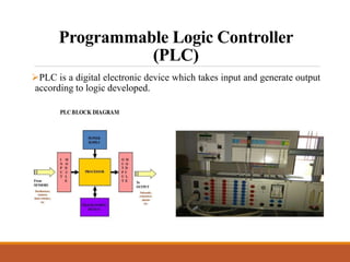
This document discusses a project on automation in liquid filling and mixing processes, focusing on the use of a Programmable Logic Controller (PLC) to enhance productivity and accuracy. It outlines the working of PLCs, different programming languages, hardware requirements, and advantages such as increased reliability and efficiency, while also noting disadvantages like high initial costs. The proposed system aims for high-speed production with minimized liquid wastage and the capability to mix varying proportions of liquids.


