Download as PDF, PPTX

![5
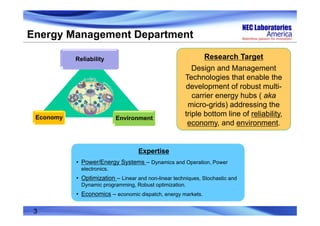
Motivation
The fluctuation of PV output power makes the
use of Energy Storage System (ESS) necessary:
• Stabilize plant output power.
• Shave grid peak power.
• Compensate grid reactive power.
The existing Battery‐Only ESS has the following
issues:
• Limited battery life cycle < 4000 cycles.
• Reduced battery lifetime as much as 50% under high
charging power.
Hybrid ESS with battery and Ultracapacitor (UC)
is a better candidate for this application [2]:
• Improved battery lifetime.
• Reduced battery size.
• Improved energy efficiency.
[1]](https://image.slidesharecdn.com/rt159fengnec-150529191707-lva1-app6892/85/RT15-Berkeley-Real-Time-Simulation-of-A-Modular-Multilevel-Converter-Based-Hybrid-Energy-Storage-System-NEC-5-320.jpg)
![Battery UltraCap
Utility Grid
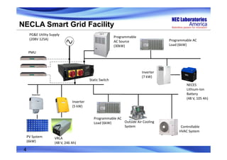
Existing Circuit Topologies
However, current Power Conversion System (PCS) of the HESS has the
following issues:
• Extra dc/dc converters are needed.
• Not suitable for high power systems (>100 kW).
• Lower reliability.
Battery
UltraCap
Utility Grid
Utility Grid
Battery
UltraCap
One dc/ac inverter [3] One dc/dc converter and one dc/ac inverter [4]
Two dc/dc converters and one dc/ac inverter [5]
6](https://image.slidesharecdn.com/rt159fengnec-150529191707-lva1-app6892/85/RT15-Berkeley-Real-Time-Simulation-of-A-Modular-Multilevel-Converter-Based-Hybrid-Energy-Storage-System-NEC-6-320.jpg)


![References
[1] A. Omran, M. Kazerani, and M.M.A. Salama, “Investigation of methods for reduction of power fluctuations
generated from large grid-connected Photovoltaic systems,” IEEE Trans. Energy Conversion, vol. 26, no.
1, pp. 318-327, Mar. 2011.
[2] Y. Ye, P. Garg, and R. Sharma, “An Integrated Power Management Strategy of Hybrid Energy Storage for
Renewable Application,” Proceedings of IECON 2014 -- The 40th Annual Conference of the IEEE Industrial
Electronics Society, 2014, pp. 3088-3093.
[3] R. Dougal, S. Liu, and R. White, “Power and life extension of battery-ultracapacitor hybrids,” IEEE Trans.
Components and Packaging Technologies, vol. 25, no. 1, pp. 120-131, Mar. 2002.
[4] L. Gao, R. Dougal, and S. Liu, “Power enhancement of an actively controlled battery/ultracapacitor hybrid,”
IEEE Trans. Power Electronics, vol. 20, no. 1, pp. 236-243, Jan. 2005.
[5] B. Hredzak, V. Agelidis, and G. Demetriades, “A Low Complexity Control System for a Hybrid DC Power
Source Based on Ultracapacitor–Lead–Acid Battery Configuration,” IEEE Trans. Power Electronics, vol. 29,
no. 6, June 2014.](https://image.slidesharecdn.com/rt159fengnec-150529191707-lva1-app6892/85/RT15-Berkeley-Real-Time-Simulation-of-A-Modular-Multilevel-Converter-Based-Hybrid-Energy-Storage-System-NEC-18-320.jpg)

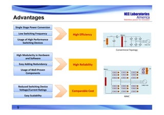
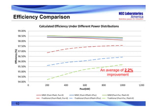
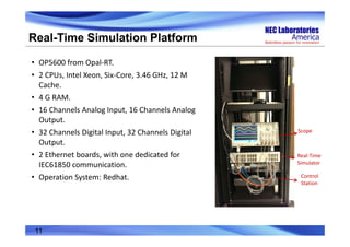
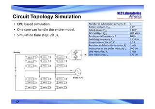
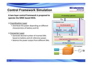
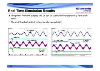
The document presents a real-time simulation of a modular multilevel converter (MMC) based hybrid energy storage system (HESS) using a battery and ultracapacitor (UC). The proposed MMC HESS offers advantages over traditional HESS topologies like higher efficiency, reliability, and comparable cost. It allows independent control of power from the battery and UC. Real-time simulation results validate the control framework and show the MMC output voltage and HESS smoothing of PV power fluctuations.