Download as PDF, PPTX
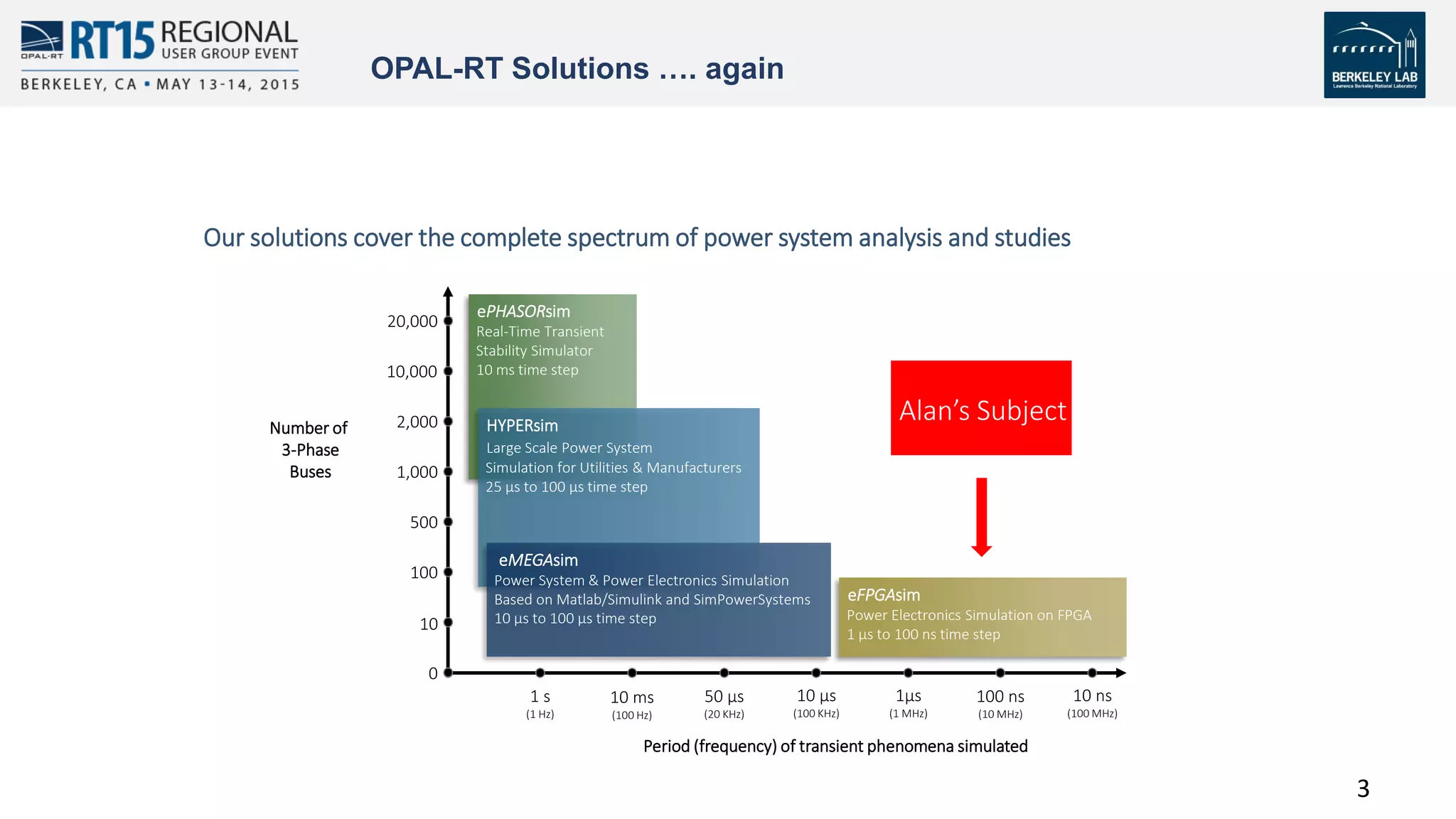
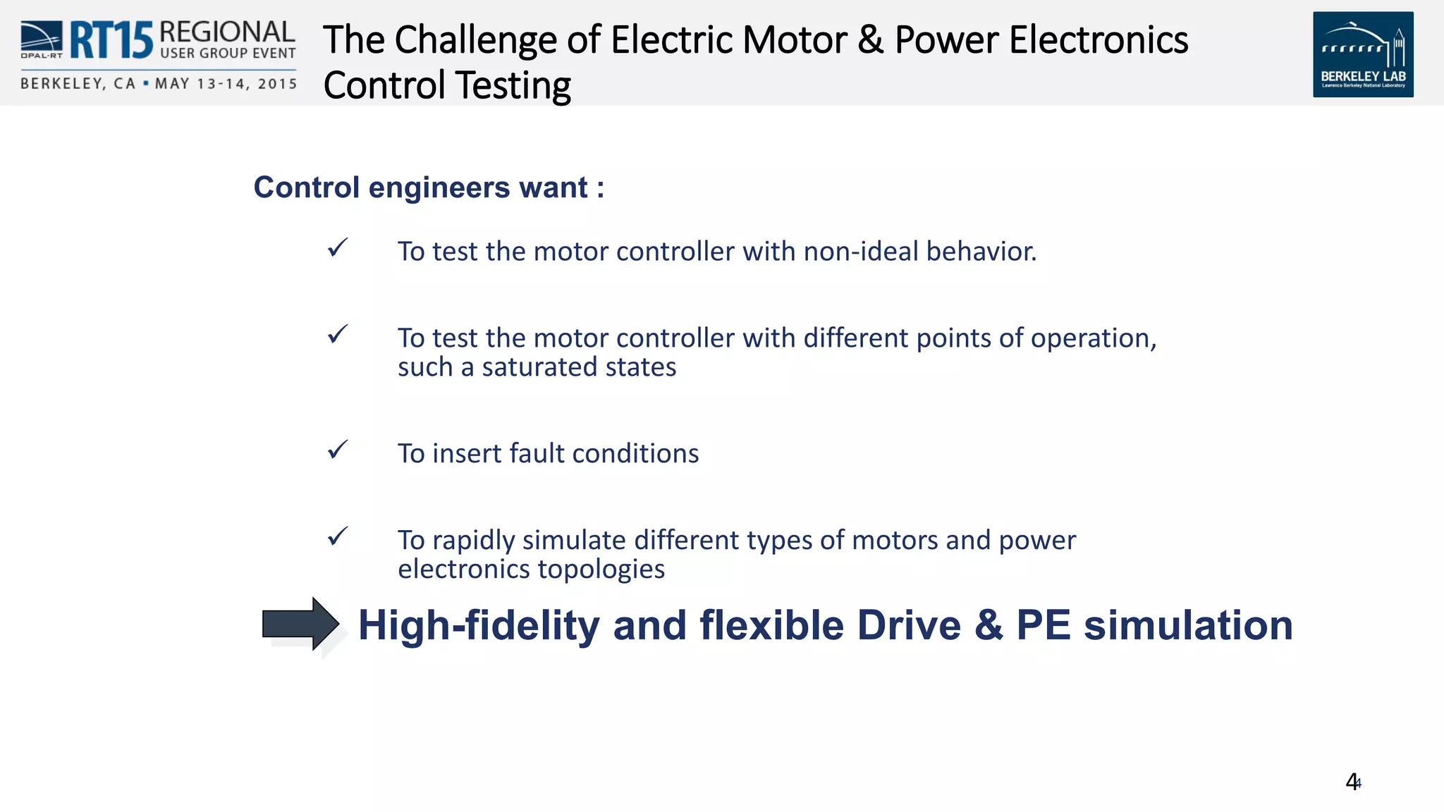
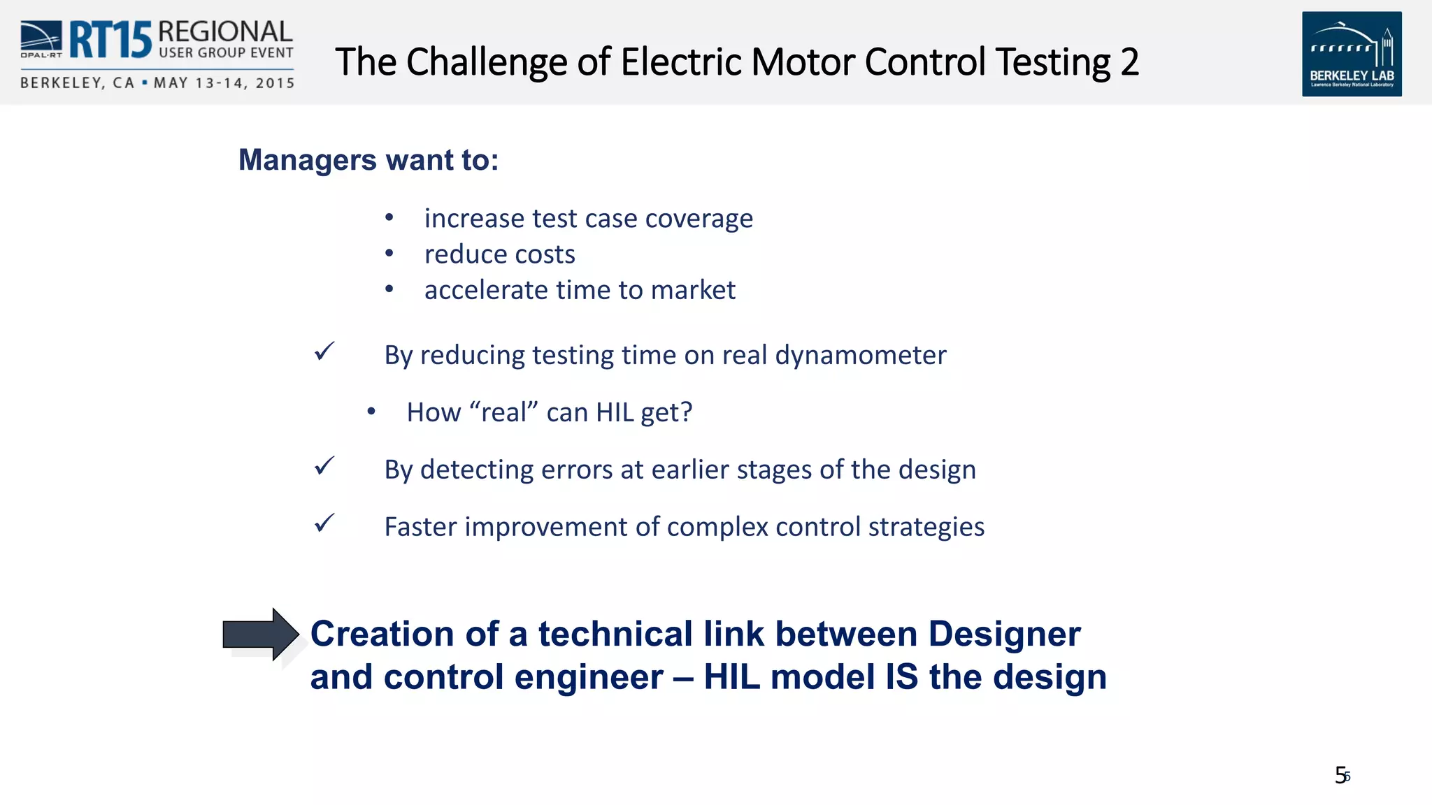
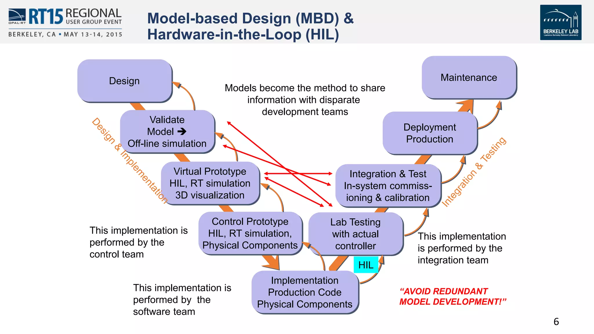
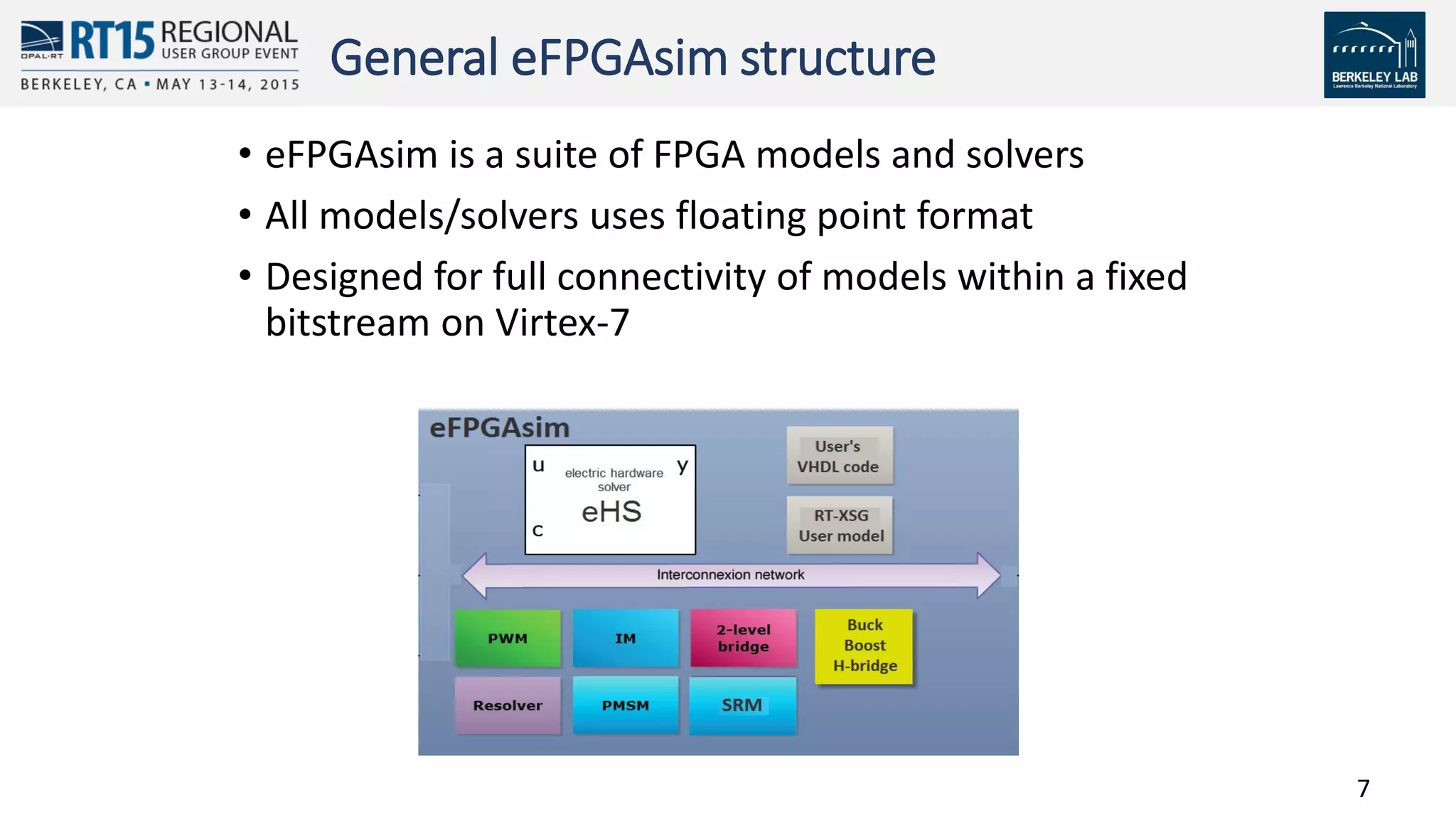
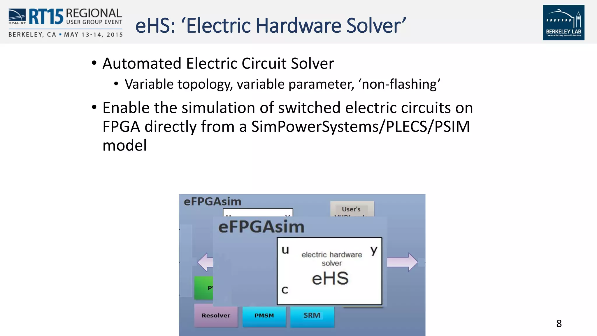
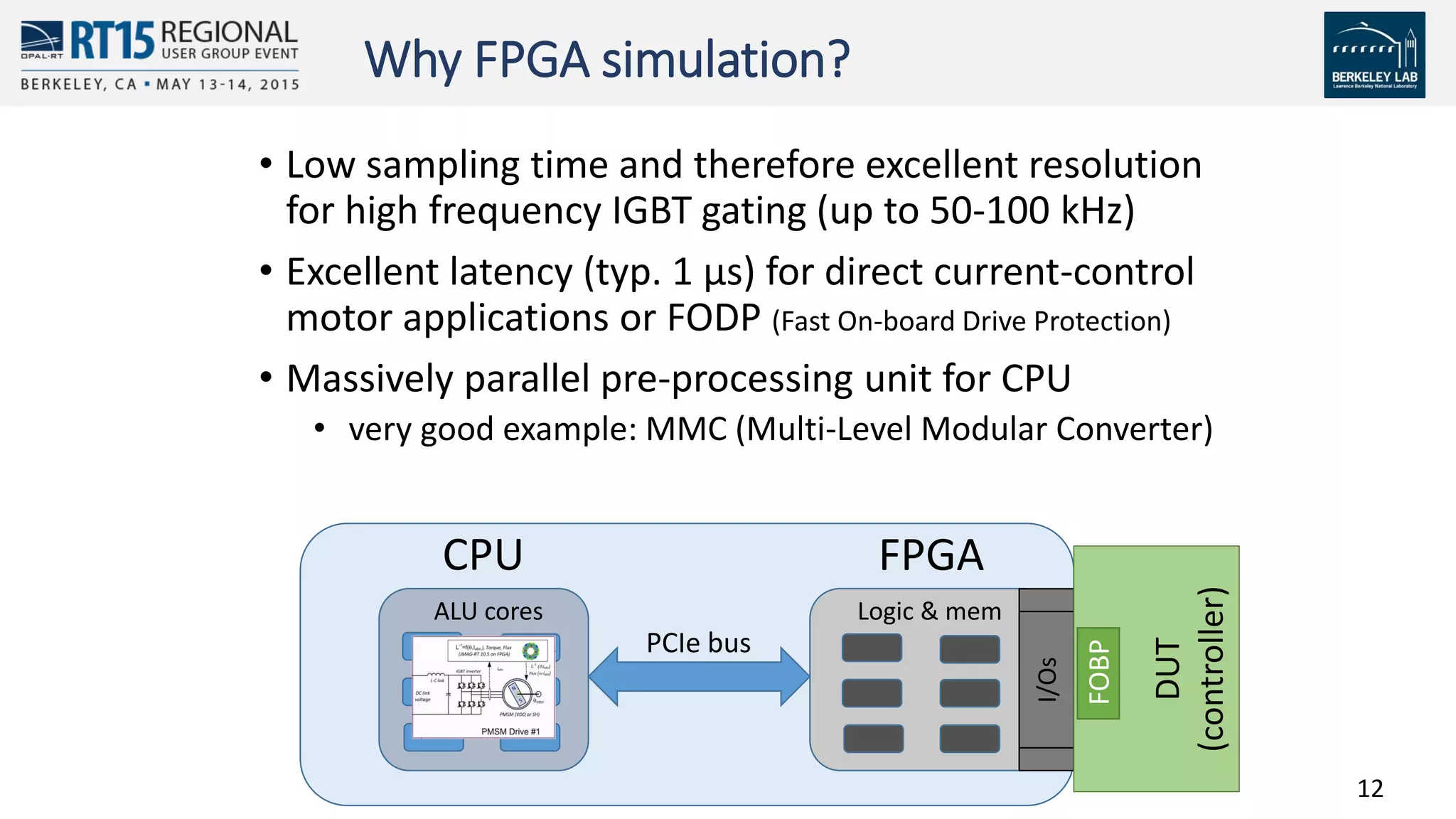
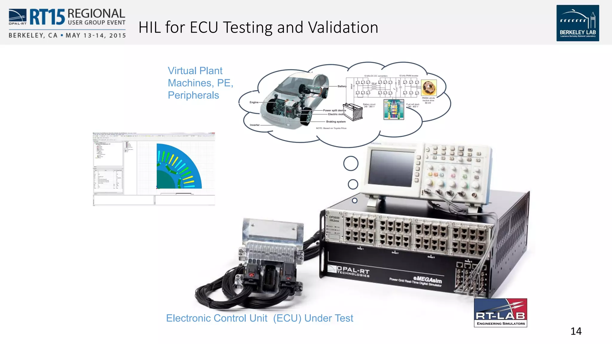
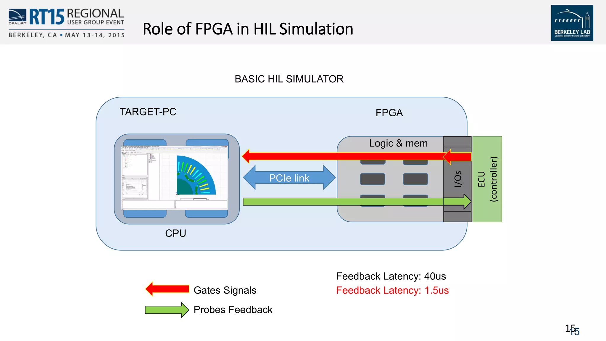
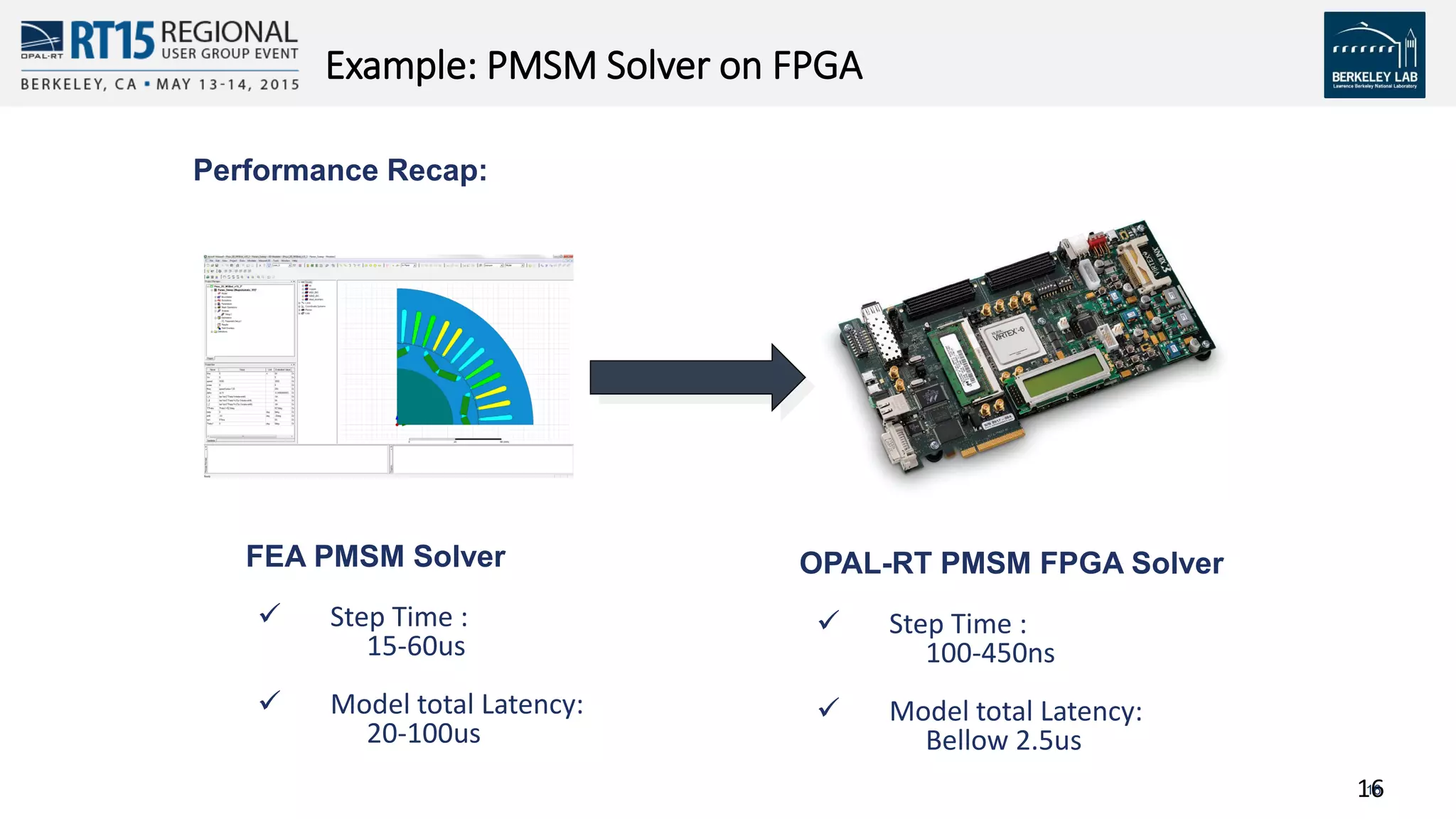
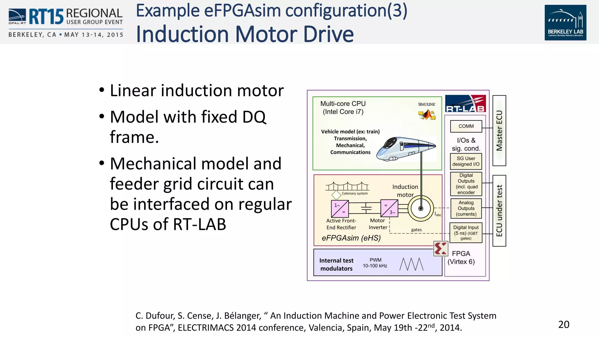
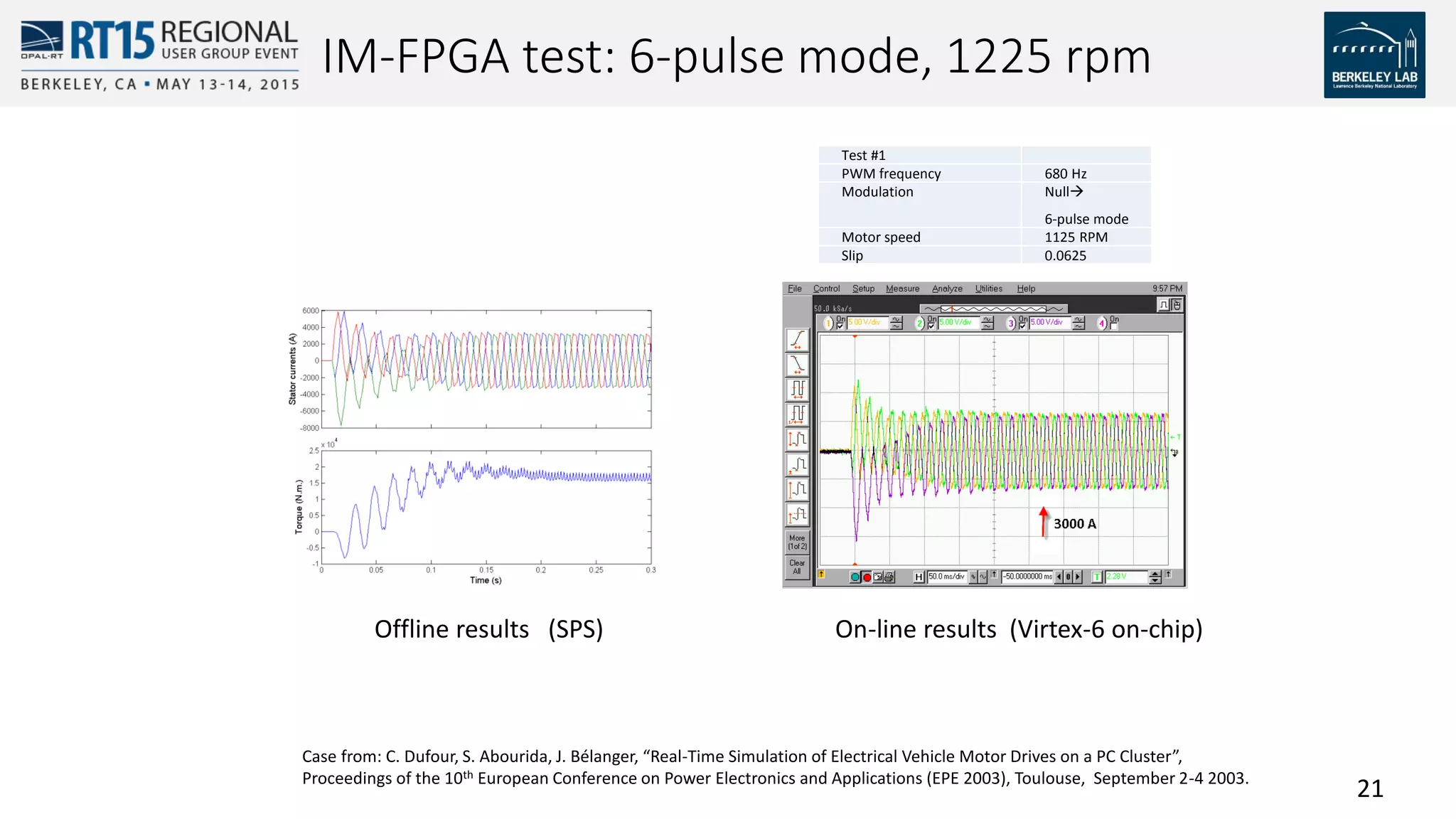
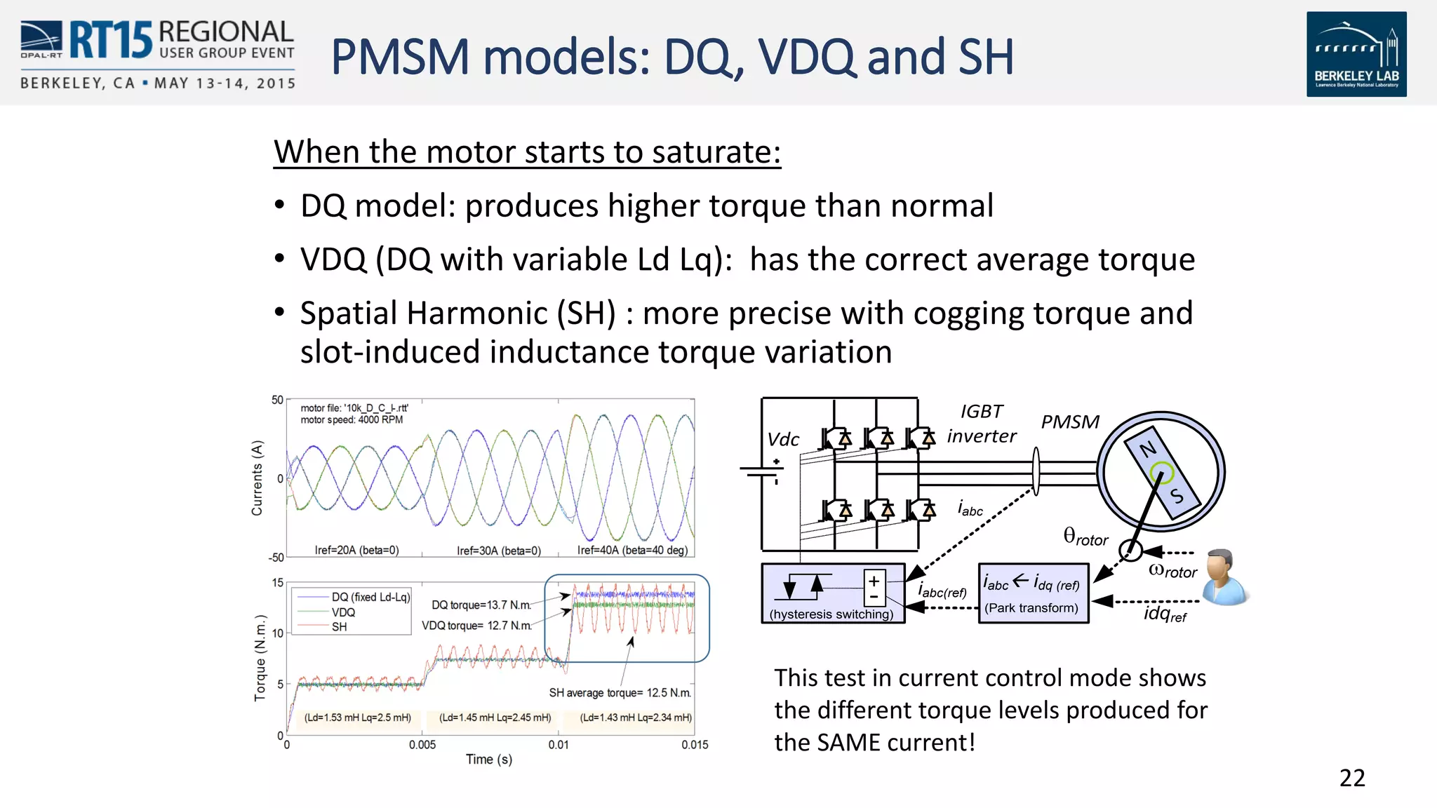
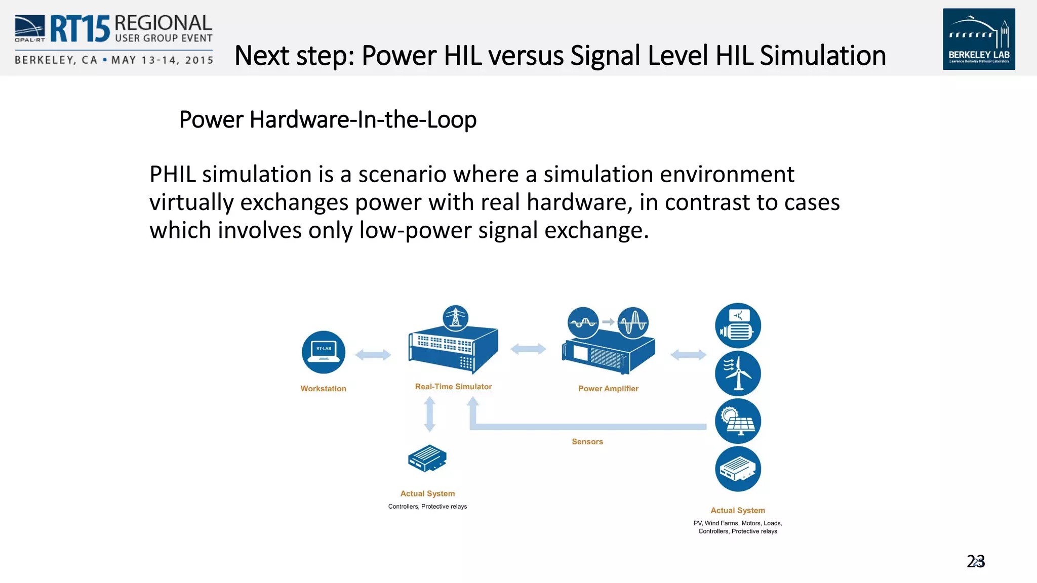
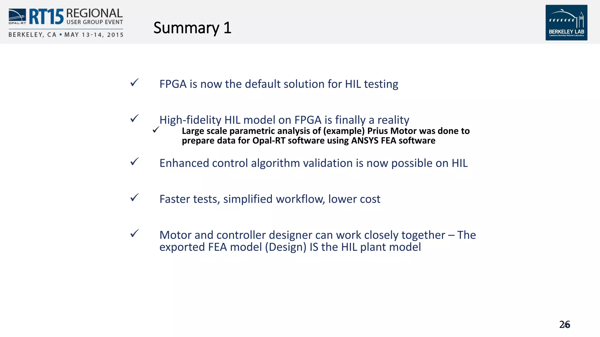
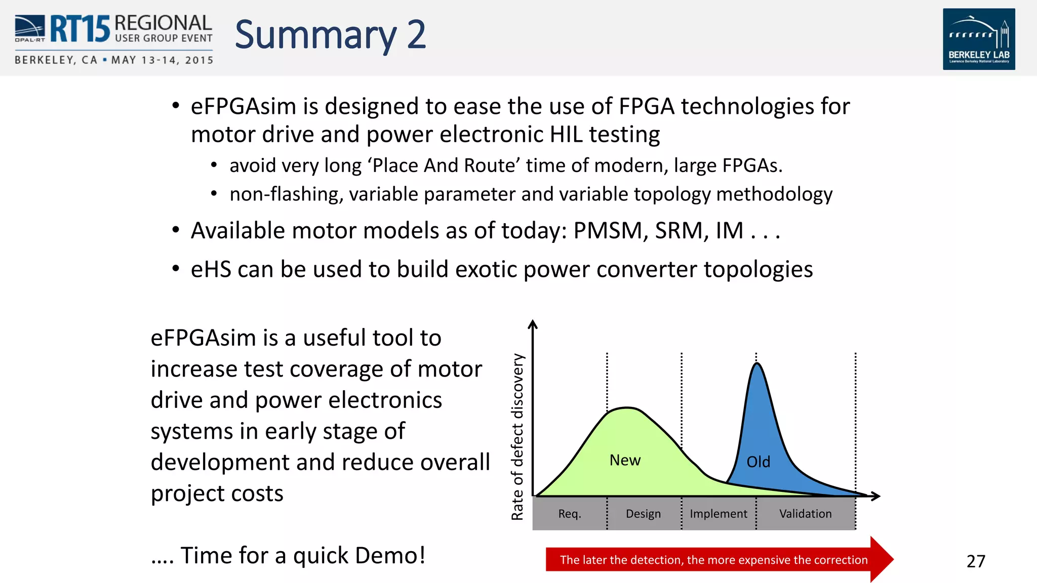

FPGA simulation provides high-fidelity models for hardware-in-the-loop testing of electric machines and power electronics. It allows control algorithms to be tested with highly resolved non-ideal behaviors faster and at lower cost compared to physical testing. The document discusses how eFPGAsim utilizes FPGA technologies to simulate electric drive systems with models exported from finite element analysis, improving collaboration between design and control engineers.