Download as PDF, PPTX


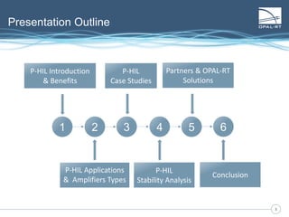
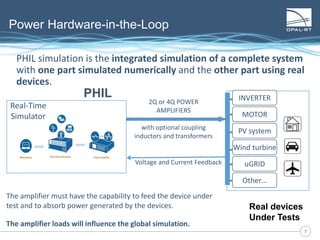
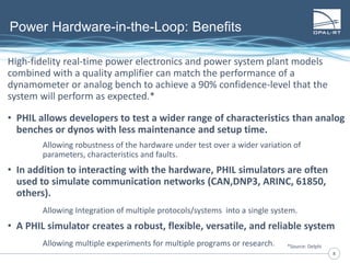
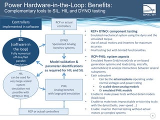
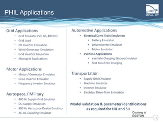
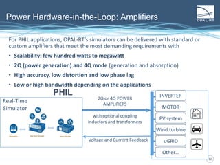
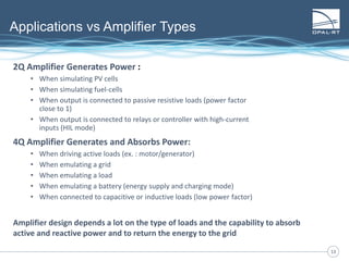
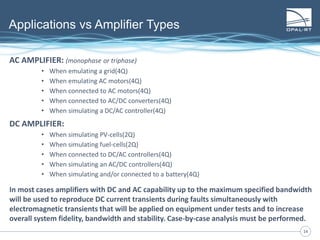
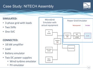
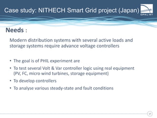
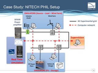
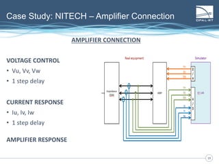
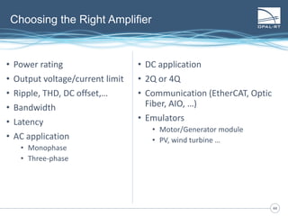
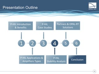
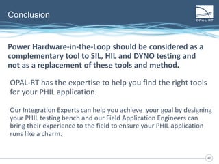


The document discusses Power Hardware-in-the-Loop (p-HIL) technology, its benefits, applications, and various types of amplifiers used in system simulations. It highlights how p-HIL allows for extensive testing of power systems and controllers, providing high levels of accuracy and flexibility compared to traditional methods. Several case studies illustrate p-HIL's application in diverse industries, including smart grids, automotive, and aerospace, emphasizing its role in enhancing the performance and reliability of power electronics systems.