Downloaded 534 times


1) HVDC transmission was first developed in the late 19th century by Rene Thury. Early systems used DC series generators and mechanical converters. 2) HVDC became more viable with the development of mercury arc valves in the 1950s and thyristor valves in the 1960s, allowing more efficient conversion between AC and DC. 3) HVDC is preferable to HVAC for long distance bulk power transmission, asynchronous connections, offshore wind connections, and other applications where HVDC has technical advantages over HVAC. Key components of HVDC systems include converters, smoothing reactors, filters, and the DC transmission line.
Presentation on HVDC transmission by Saurabh Dayal Singh in Electrical Engineering, guided by Mrs. Shradha Gautam.
Outline of evolution from the first DC power system by Edison in 1882 to the development of AC systems by Tesla and their eventual dominance.
Description of the introduction of HVDC systems by Rene Thury, followed by the resurgence of AC systems due to high maintenance costs of DC.
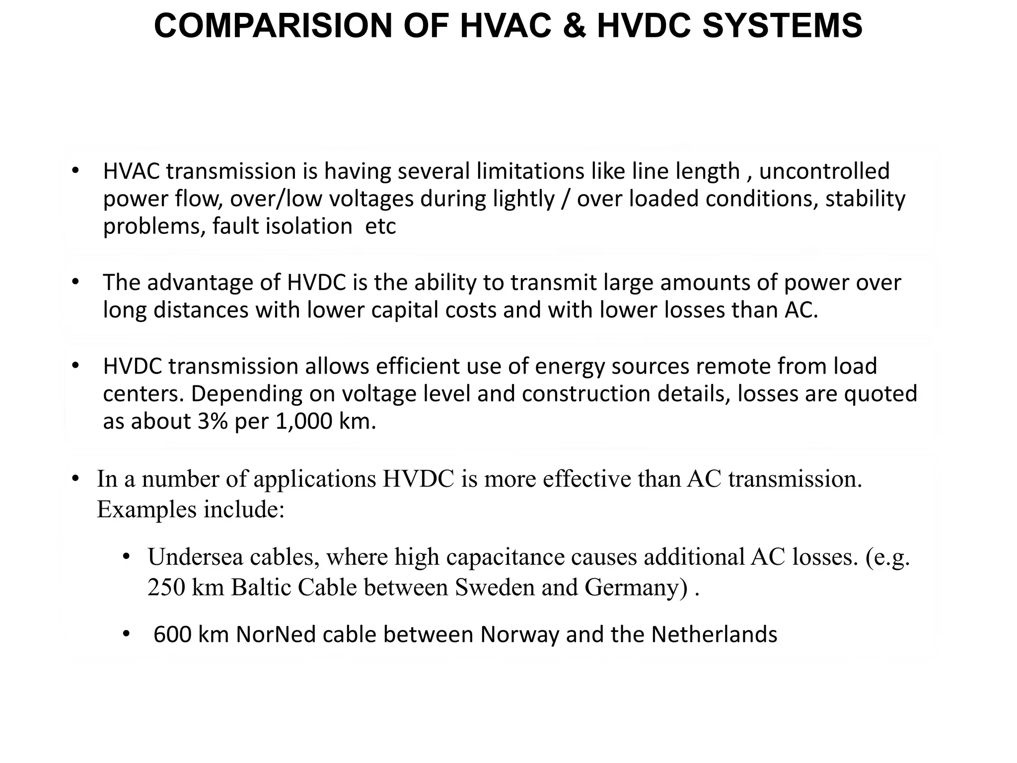
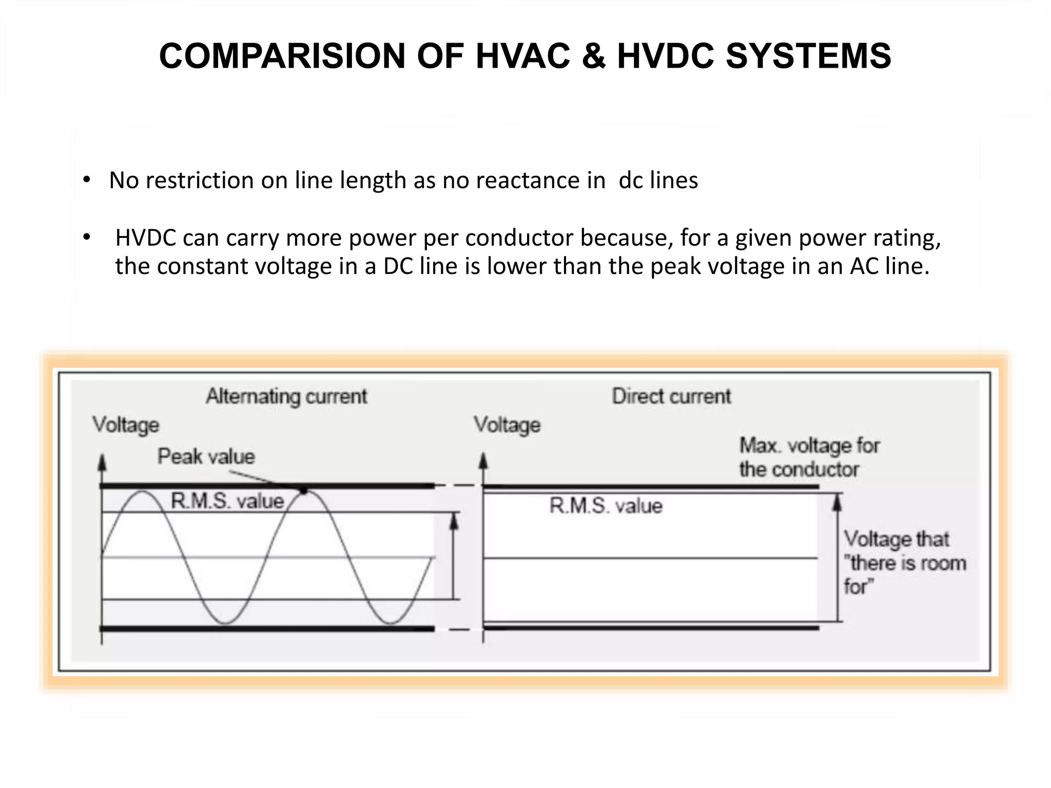
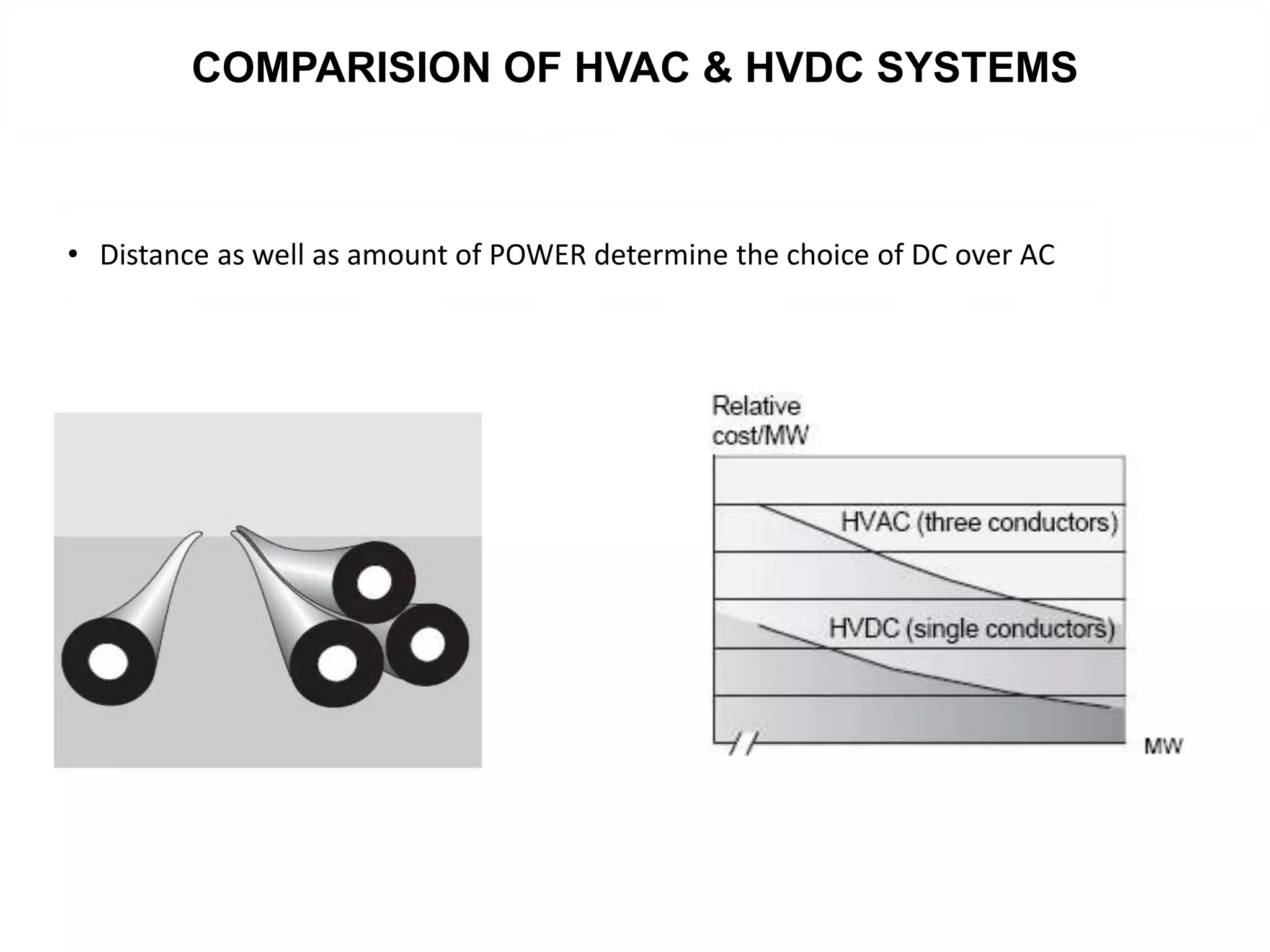
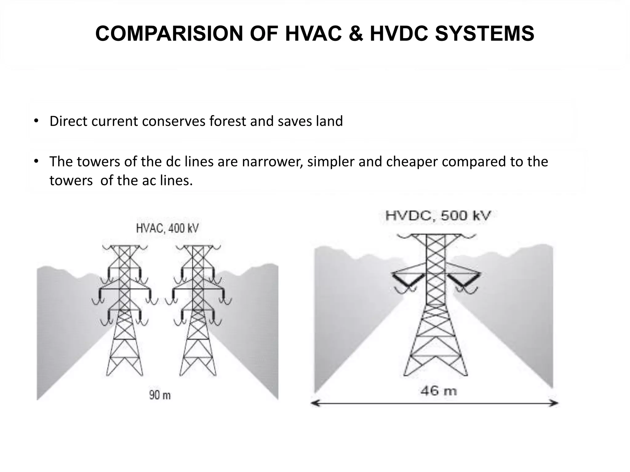
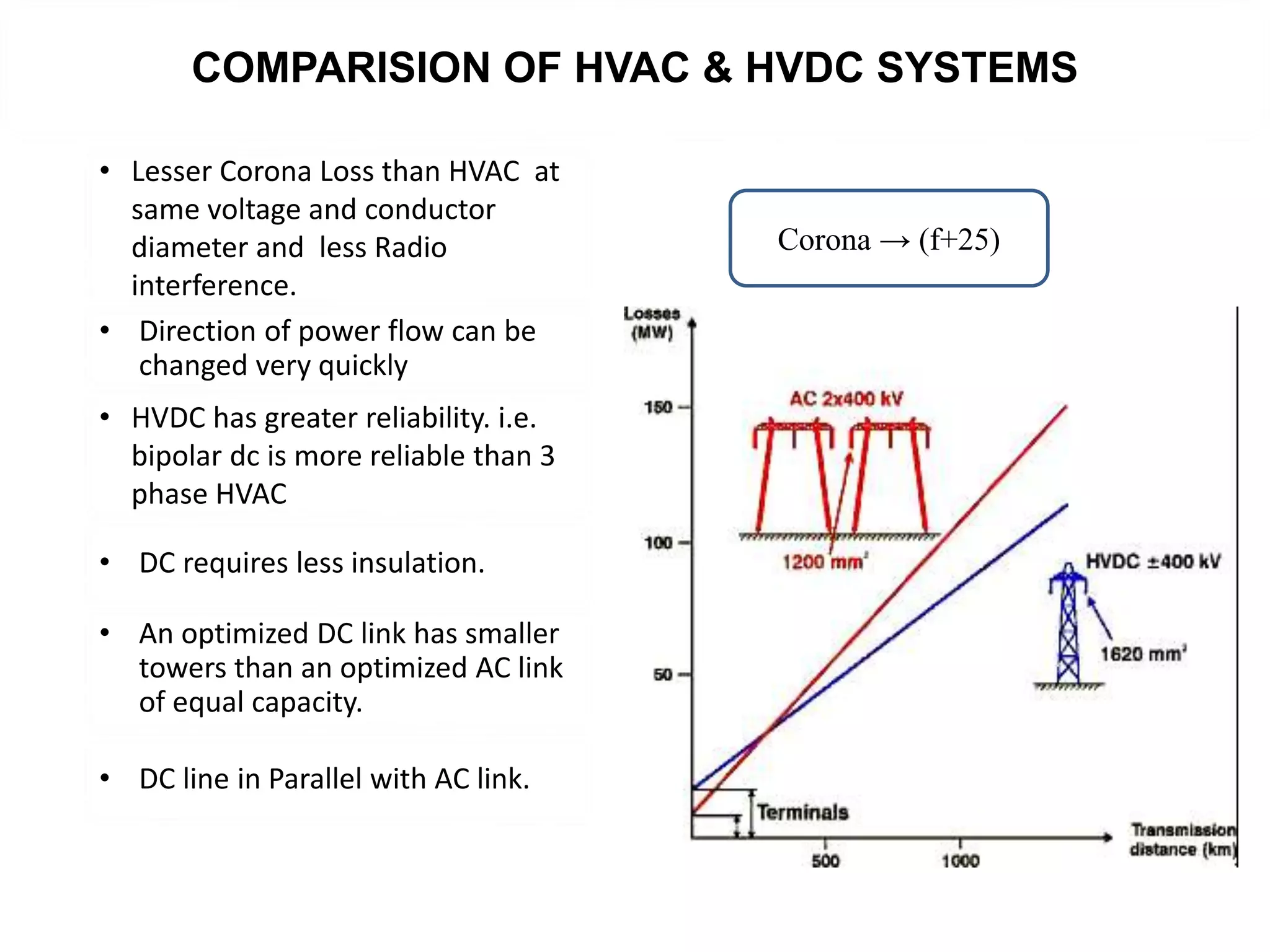
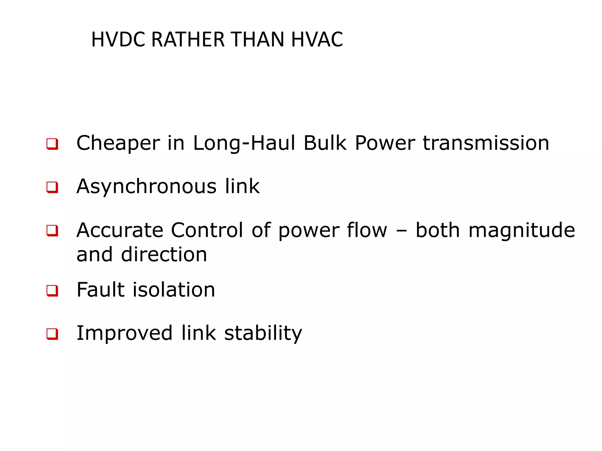
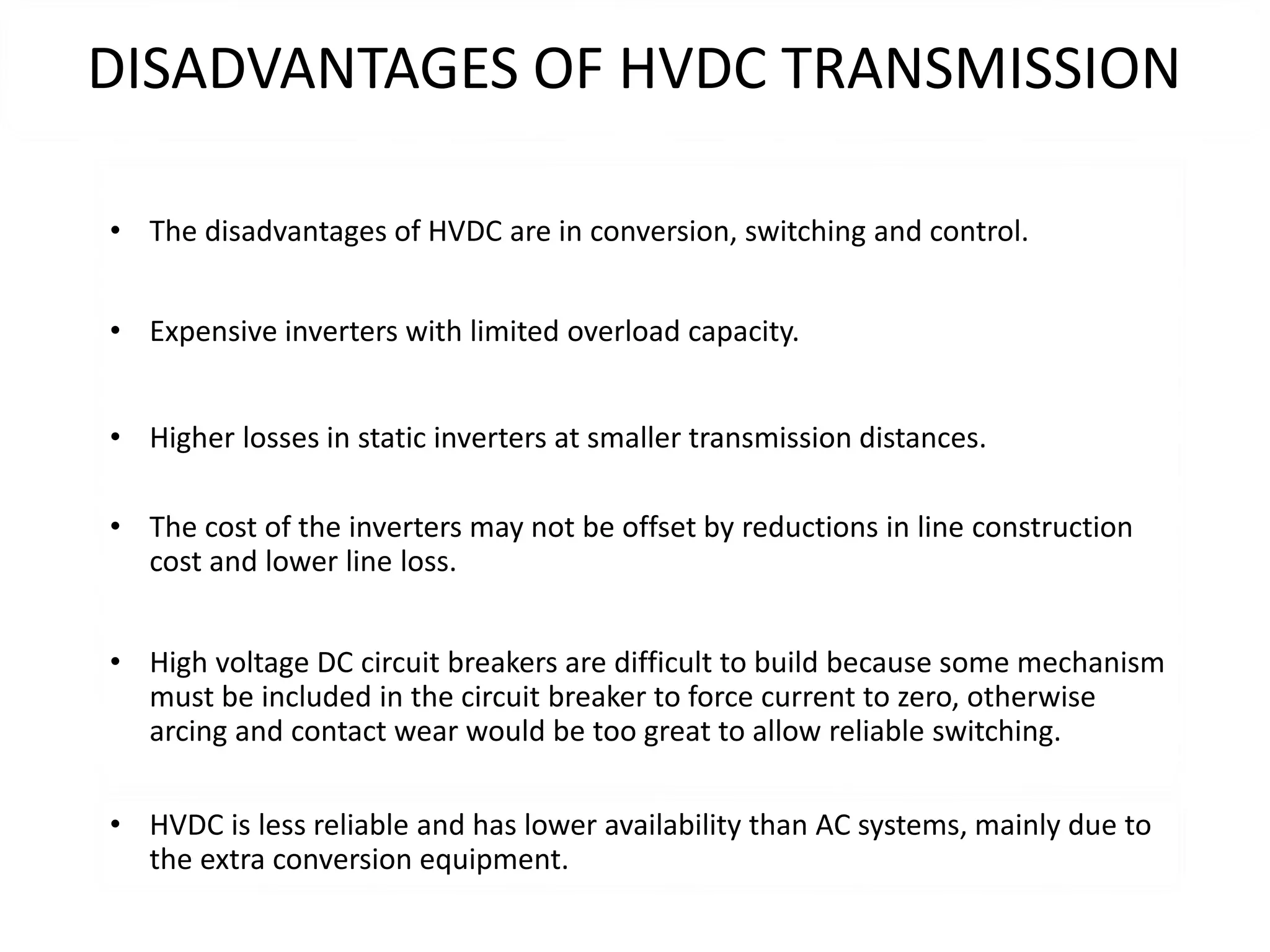
Discussion of HVDC advantages over HVAC, including lower costs for long-distance transmission, efficient power transmission, and reduced losses.
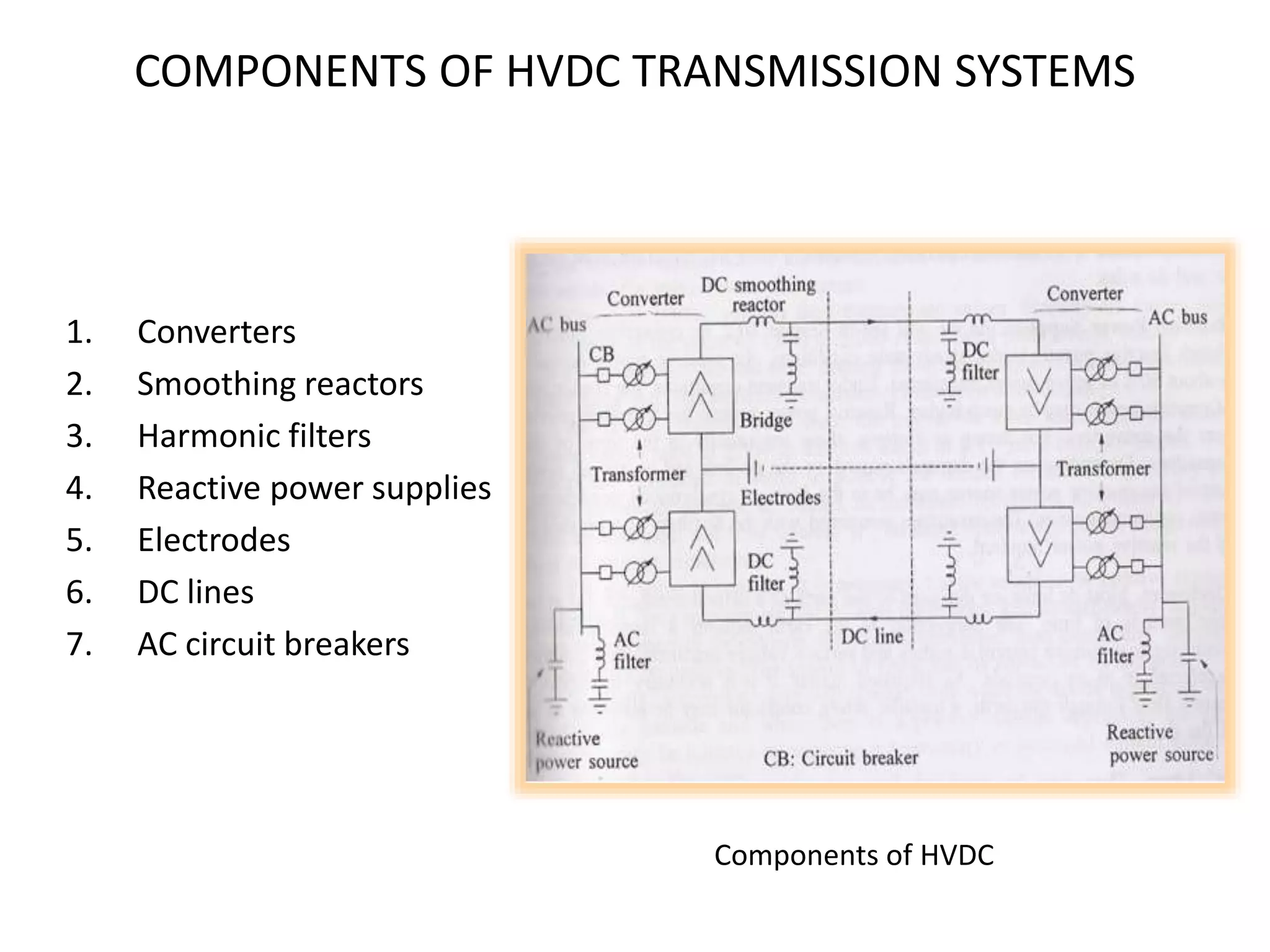
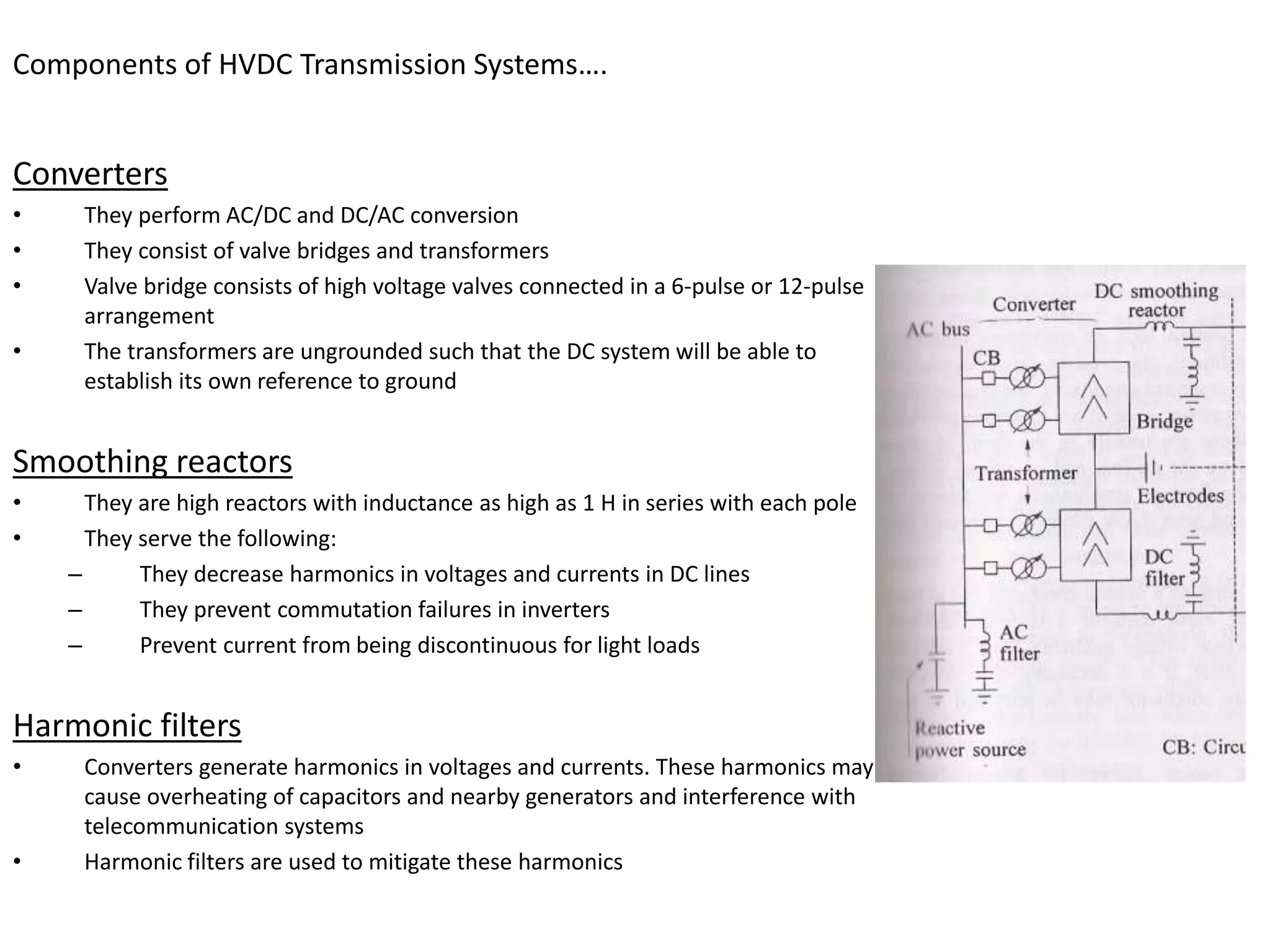
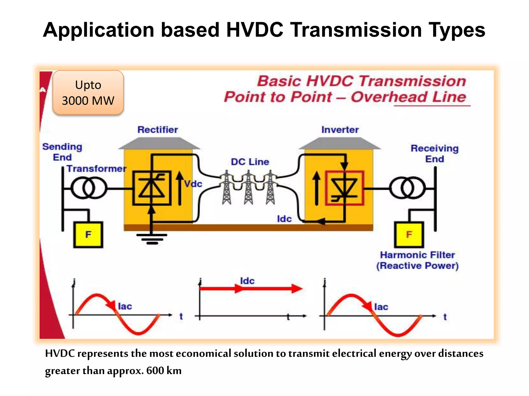
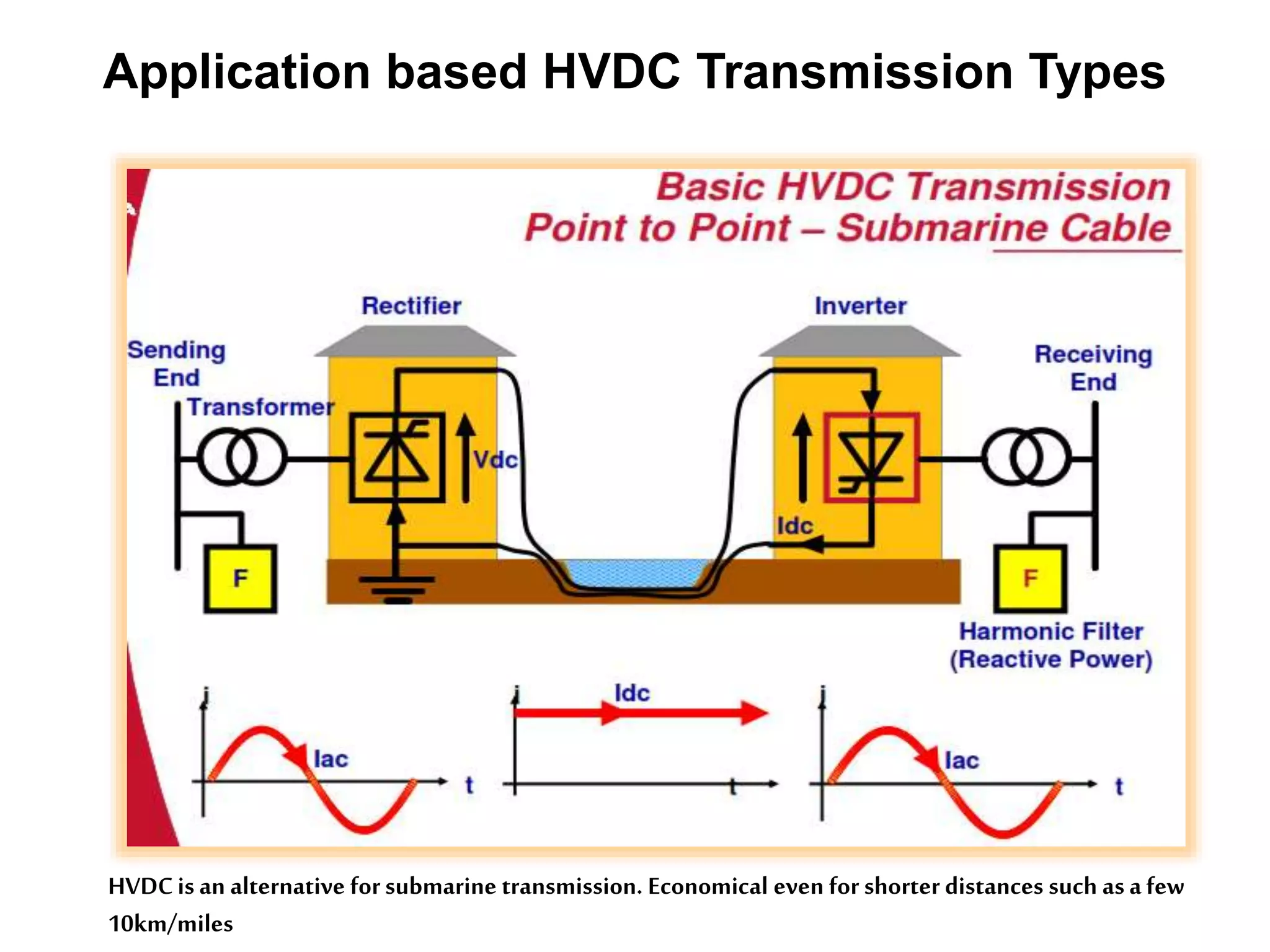
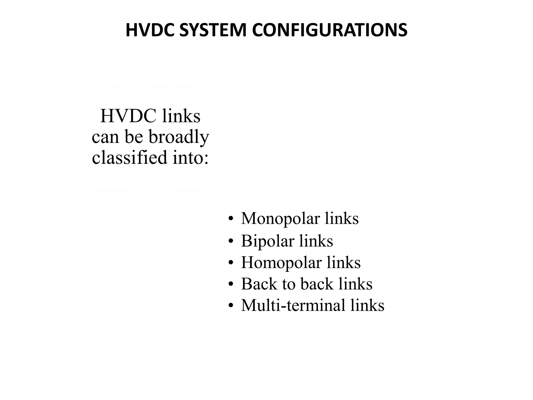
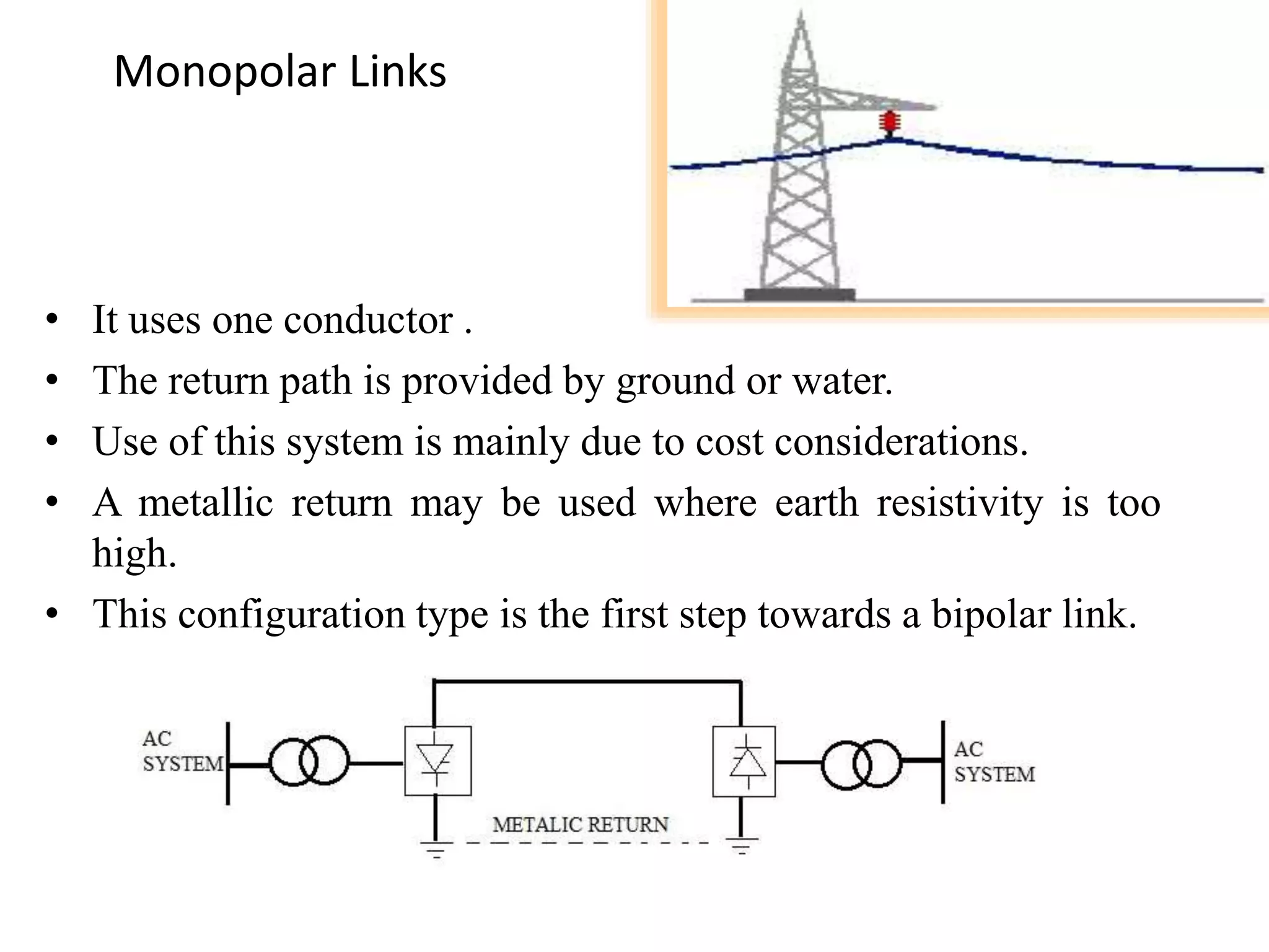
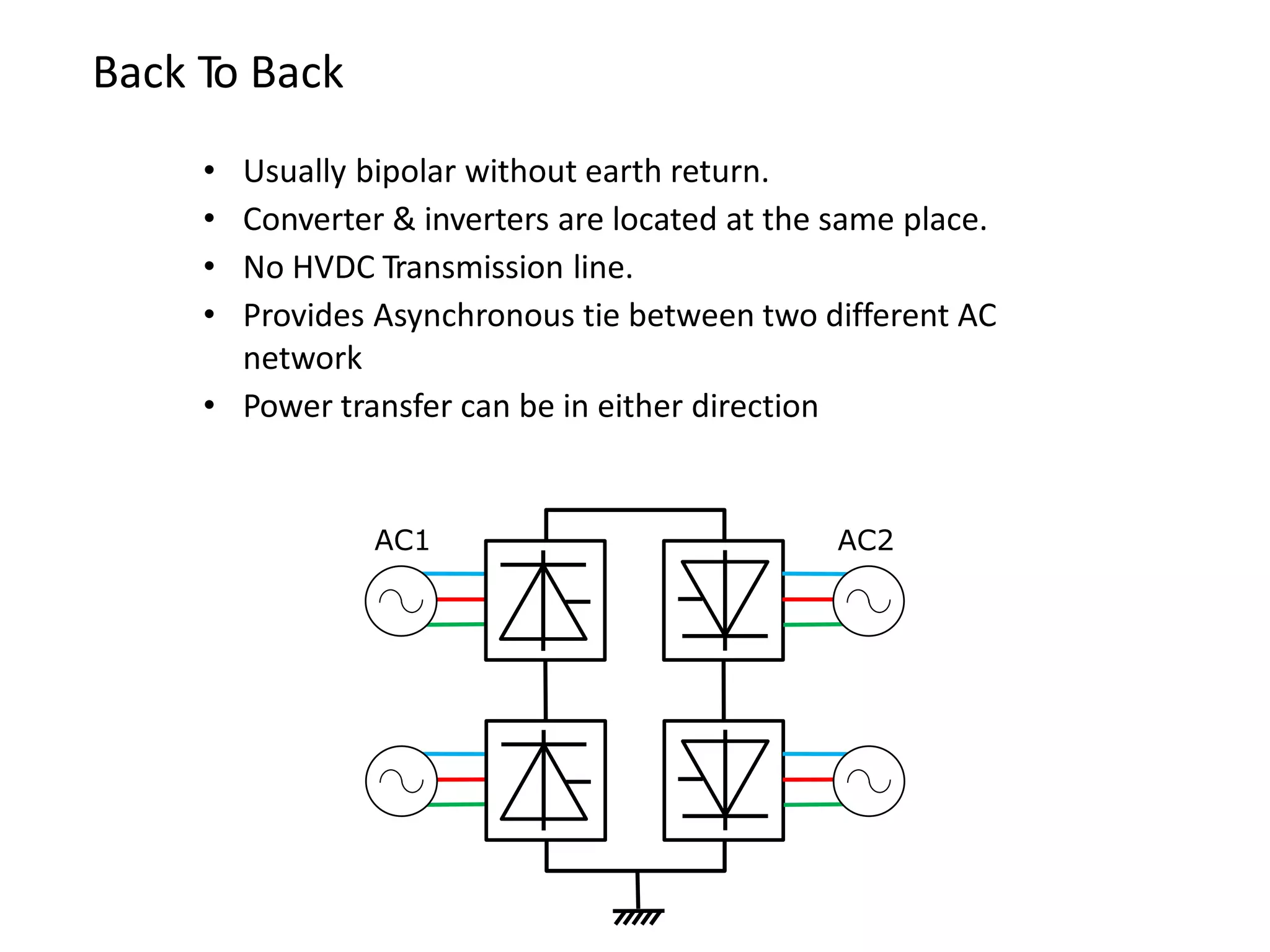
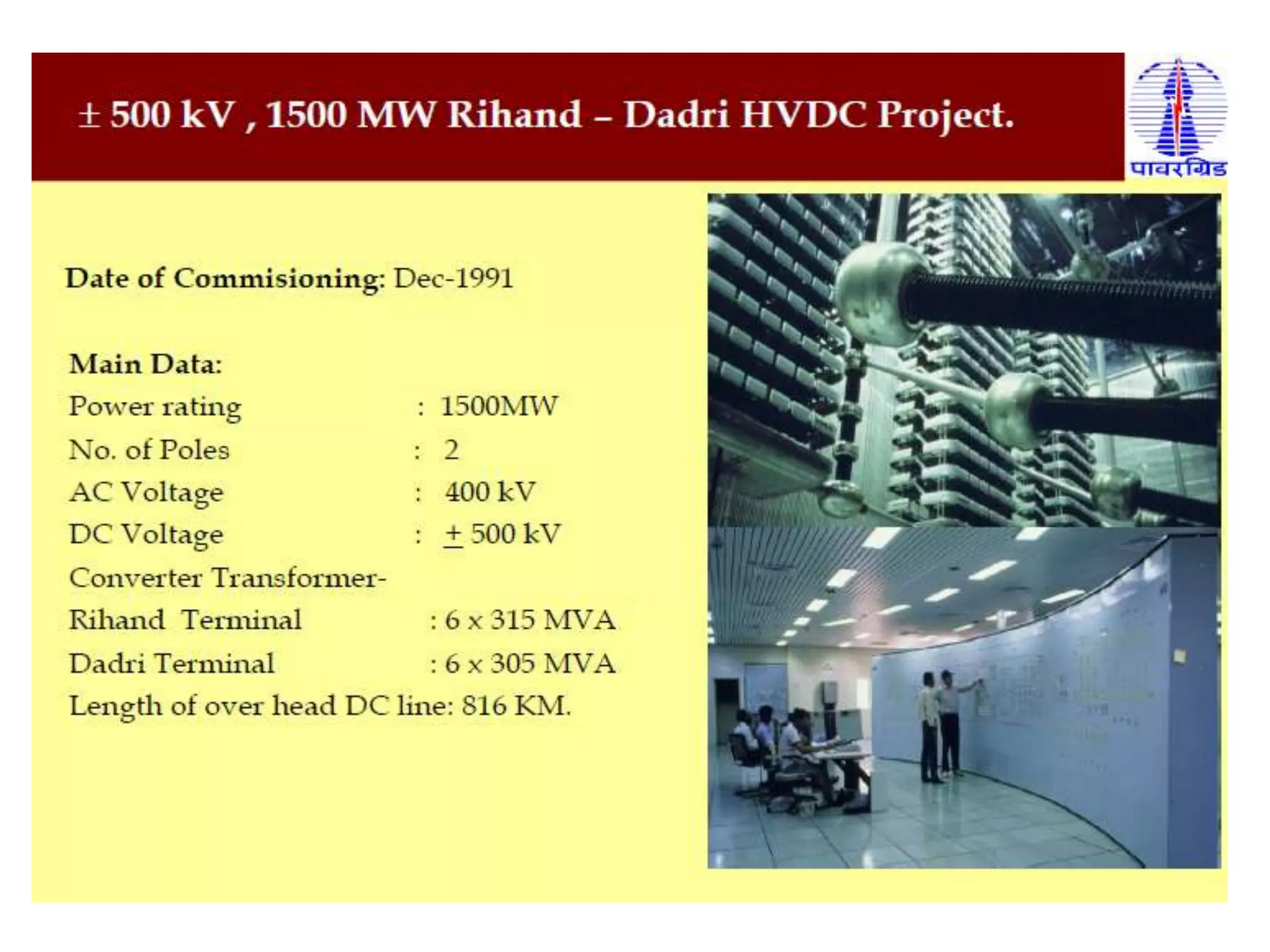
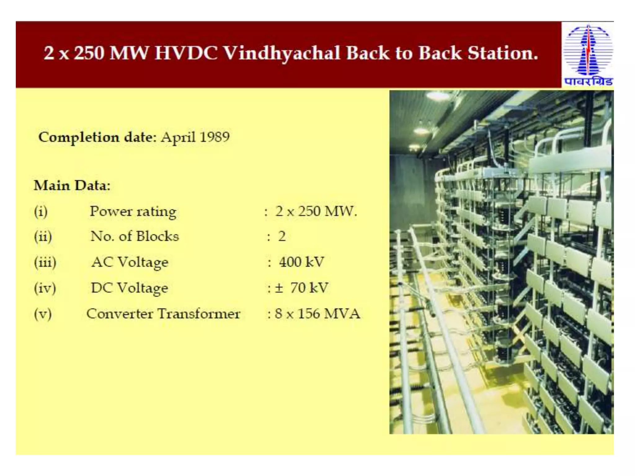
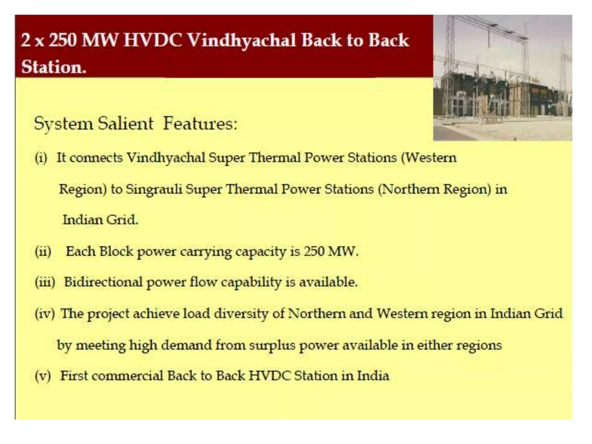
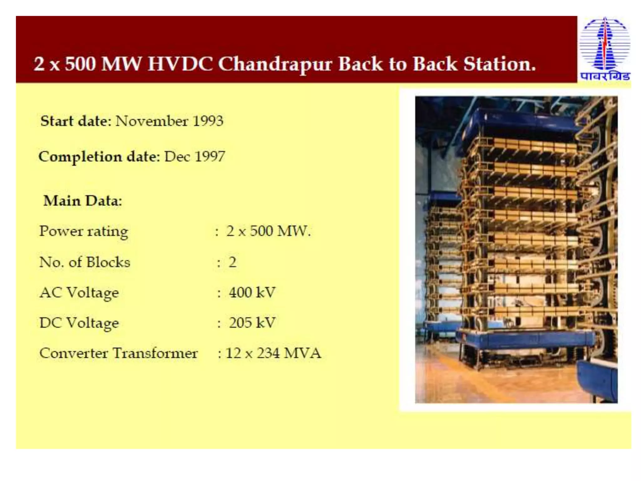
Components of HVDC systems like converters, reactors, and filters, along with configurations such as monopolar, bipolar, and multi-terminal systems.
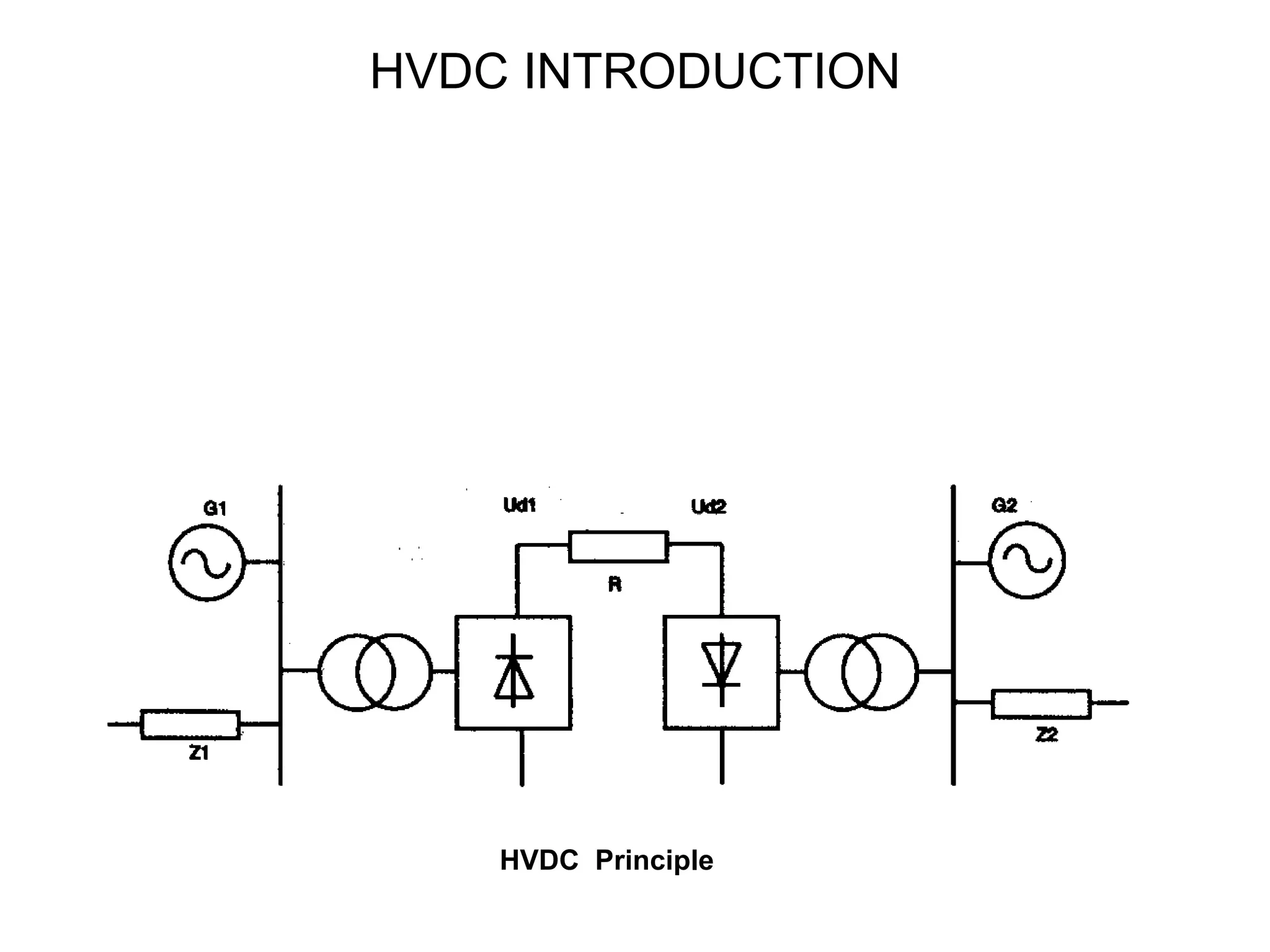
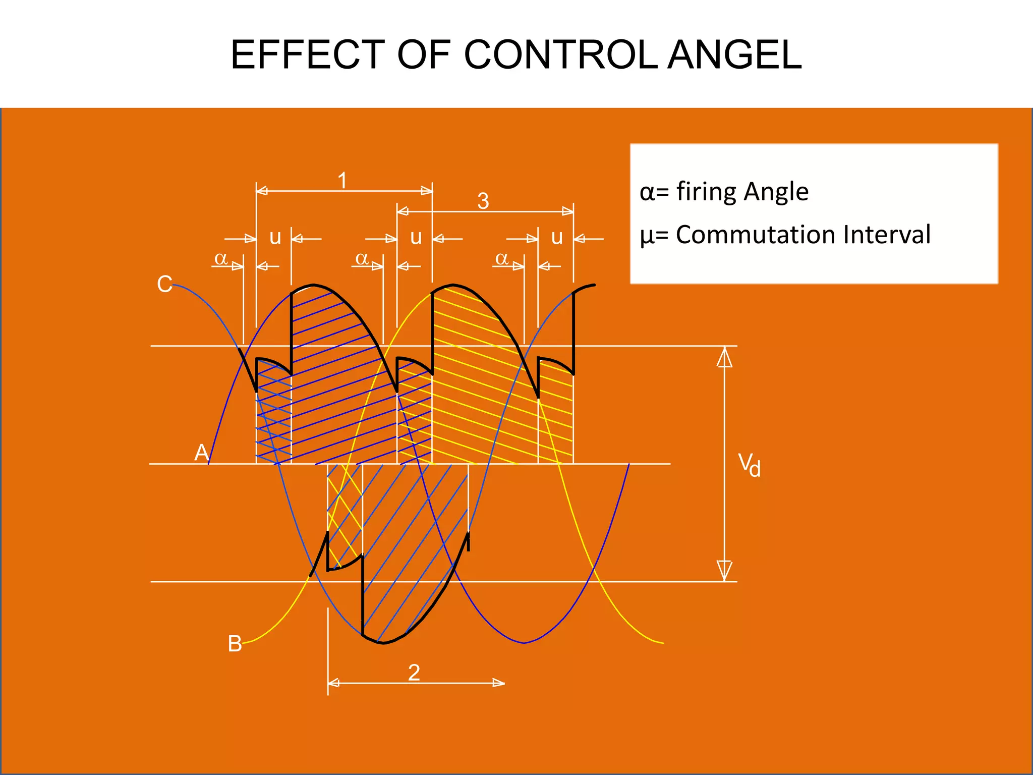
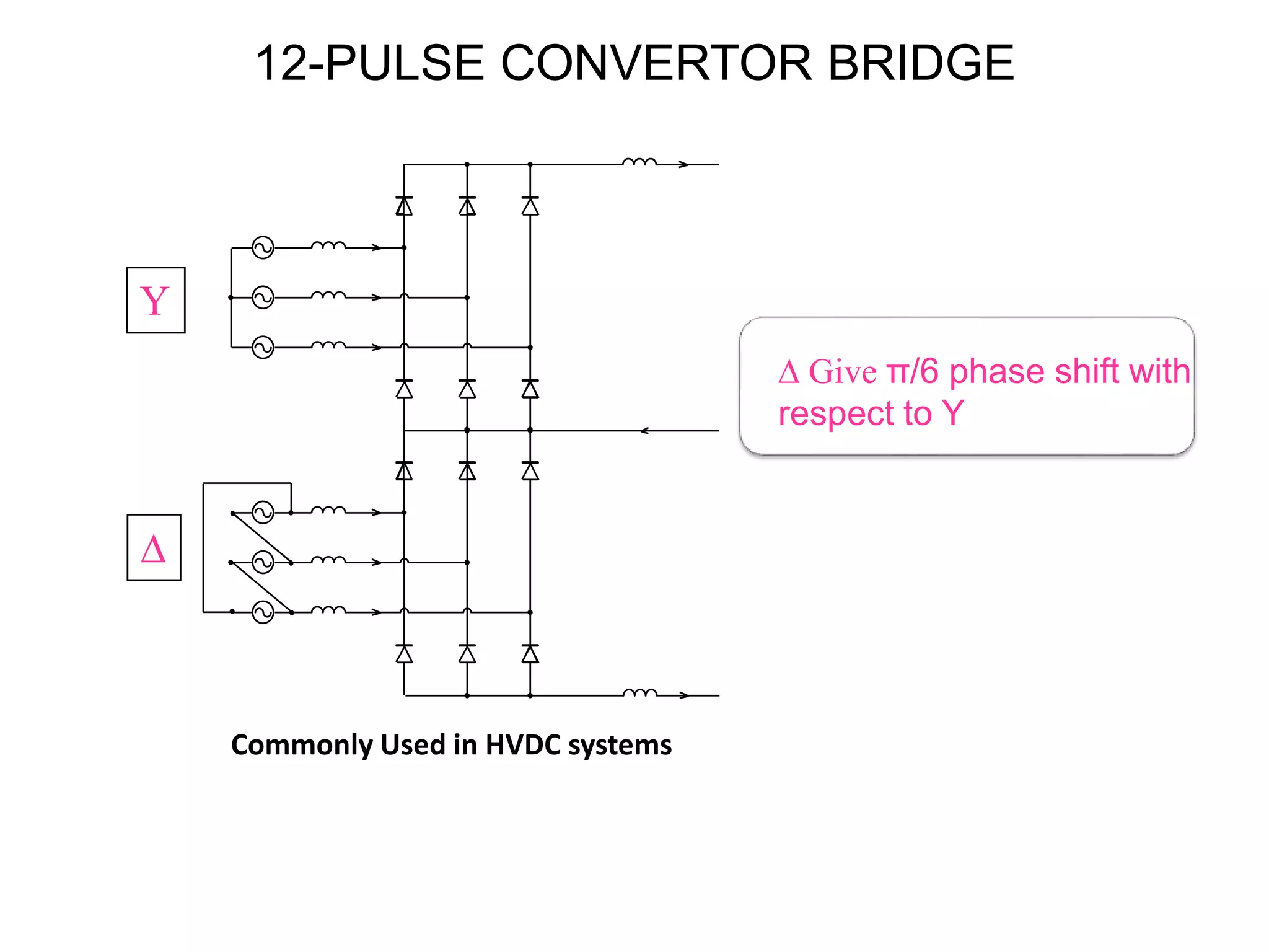
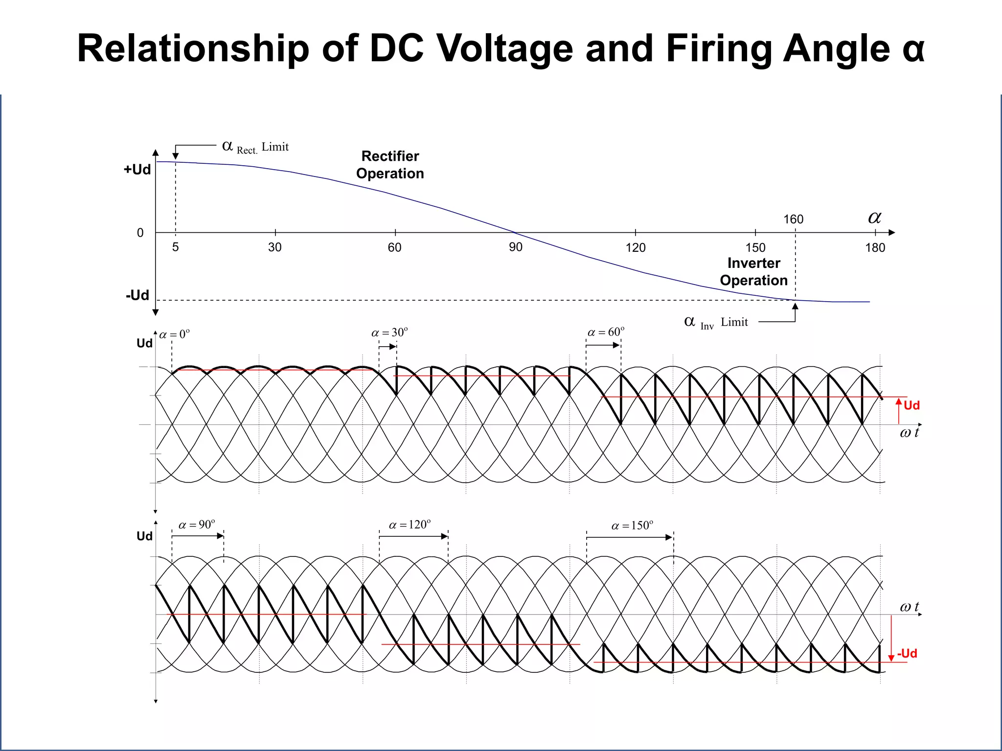
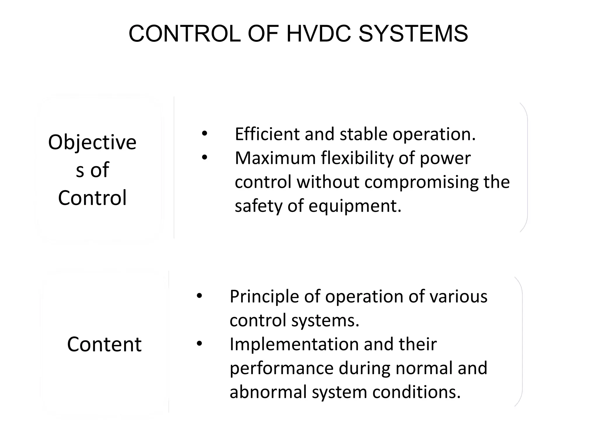
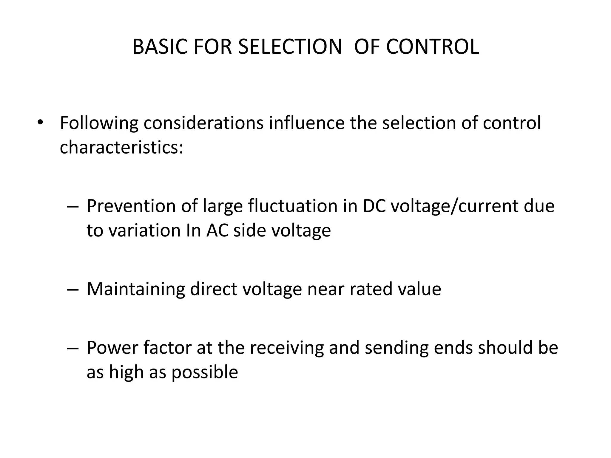
Overview of the principles of DC transmission, operation of single phase and six pulse rectifiers, and control of DC voltage.
Explanation of Voltage Source Converters for HVDC systems and applications in long distance, bulk power transmission, and asynchronous connections.
Final thoughts on the importance of HVDC in energy transmission, reliability in operation, and the growing investments in HVDC technology.