Download as PDF, PPTX

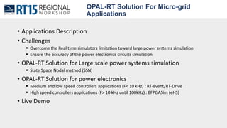
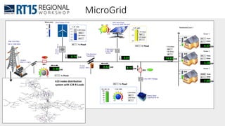
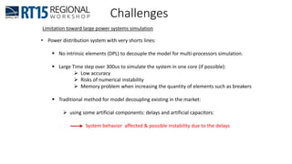
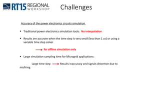
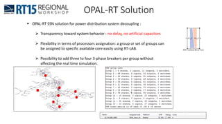
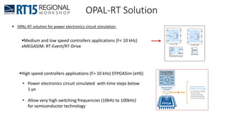

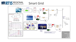
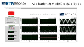
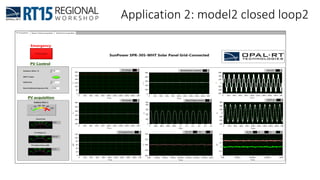
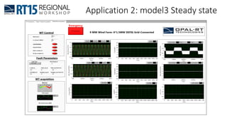
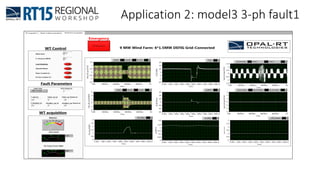


This document discusses OPAL-RT's solution for microgrid applications real-time simulation. It addresses challenges in simulating large power systems and ensuring accuracy of power electronics circuits. OPAL-RT's State Space Nodal method allows simulation of large power distribution systems across multiple processors without affecting system behavior. It also supports accurate power electronics simulation from medium-speed to high-speed controllers using various OPAL-RT tools. The document demonstrates these capabilities through a live demo of a microgrid system.