Download as PDF, PPTX
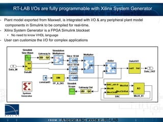
![ Parametric sweep table of 17195 rows:
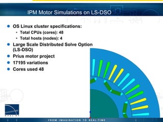
• Beta = 0:20:360
• Theta = 0:0.25:45
• Iamp = 0:50:200
Parametric table was run on (LS-DSO)
Results post-processed using Matlab
Final Table:
• Beta = 0:5:360
• Theta = 0:0.25:45
• Iamp =
[0,2.5,5,8,11,18,25,37.50,50,75,100,125,150,17
5,20]
Note: Results were post-processed using
spline interpolation in Matlab
IPM Motor Simulations on LS-DSO](https://image.slidesharecdn.com/opalrtansyshilsimulation2013-140819144458-phpapp01/85/OPAL-RT-and-ANSYS-HIL-simulation-27-320.jpg)


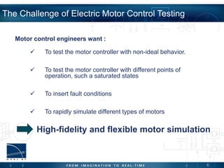
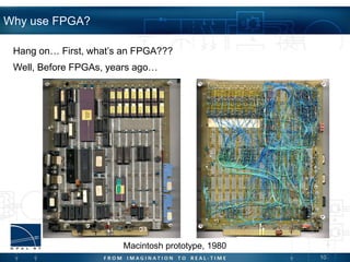
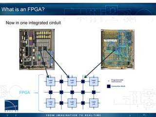
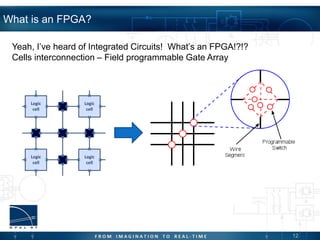
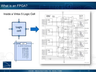
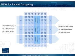
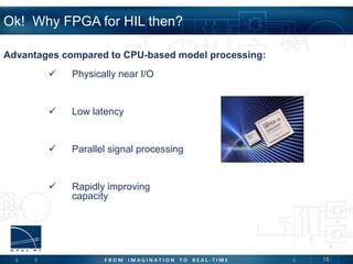
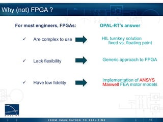
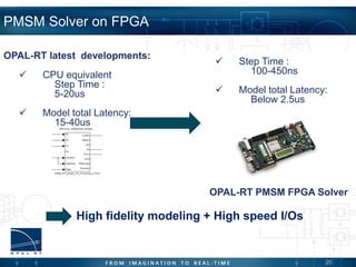
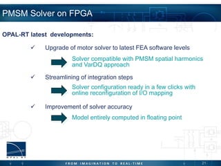
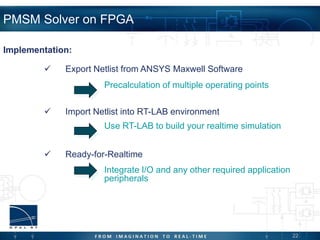
This document discusses using FPGAs for hardware-in-the-loop simulation of electric machines. It begins with an introduction to HIL simulation and why FPGAs are advantageous compared to CPUs for modeling electric drives. It then describes implementing a permanent magnet synchronous motor solver on an FPGA for high-fidelity, high-speed modeling. The document shows how FEA models from ANSYS Maxwell can be exported and integrated with I/O interfaces on an FPGA-based real-time simulator from OPAL-RT to perform HIL simulation. Benchmark simulations of a Prius motor model exported from Maxwell and run on an OPAL-RT system demonstrate the benefits of using FPGAs for electric machine HIL modeling.