Download as PDF, PPTX

![Procedure
Step 1 Map instance 1 to VLANs 100 and 200.
[Switch-A]stp region-configuration
[Switch-A-mst-region]instance 1 vlan 10 11 100 200
[Switch-A-mst-region]active region-configuration
The configurations of Switch B and Switch C are similar to the
configuration of Switch A. The detailed configurations are omitted here.
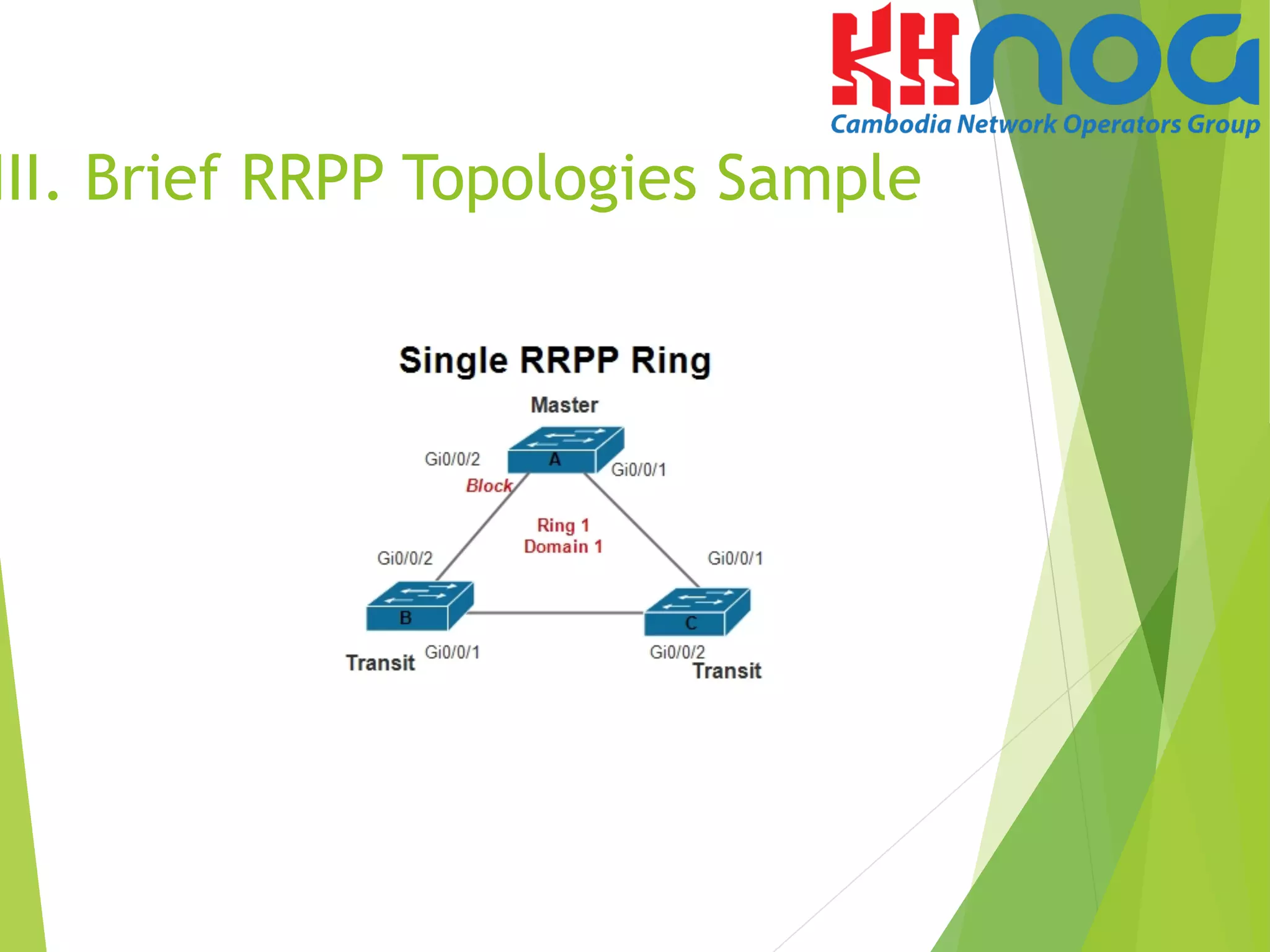
V. Configuration sample of
Single RRPP Ring
Step 2 Create an RRPP domain and the control VLAN.
# On the master node of ring 1, namely Switch -A, create RRPP domain 1 and c
configure VLAN 10 as the main control VLAN.
[Switch-A]rrpp domain 1
[Switch-A-rrpp-domain-region1]control-vlan 10
# On the transit node of ring 1, namely Switch B, create RRPP domain 1 and configure
VLAN 10 as the main control VLAN.
[Switch-B] rrpp domain 1
[Switch-B-rrpp-domain-region1] control-vlan 10
# On the master node of ring 1, namely SwitchC, create RRPP domain 1 and configure
VLAN 10 as the main control VLAN.
[Switch-C] rrpp domain 1
[Switch-C-rrpp-domain-region1] control-vlan 10](https://image.slidesharecdn.com/mr-160902015528/75/Rapid-Ring-Protection-Protocol-RRPP-22-2048.jpg)
![Procedure
Step 3 Configure the interfaces to be added to the RRPP ring as trunk
interfaces, allow VLANs 100 and 200 on the interfaces, and disable STP
on the interfaces.
# Configure Switch A.
[Switch-A]interface gi0/0/1
[Switch-A-GigabitEthernet0/0/1]port link-type trunk
[Switch-A-GigabitEthernet0/0/1]port tru all vla 100 200
[Switch-A-GigabitEthernet0/0/1]stp disable
[Switch-A]interface gi0/0/2
[Switch-A-GigabitEthernet0/0/2]port link-type trunk
[Switch-A-GigabitEthernet0/0/2]port trunk allow-pass
vlan 100 200
[Switch-A-GigabitEthernet0/0/2]stp disable
V. Configuration sample of
Single RRPP Ring
Note: The configurations on interfaces of Switch B and switch C are the same to
the configuration of Switch A. The detailed configurations are omitted.](https://image.slidesharecdn.com/mr-160902015528/75/Rapid-Ring-Protection-Protocol-RRPP-23-2048.jpg)
![Procedure
Step 4 Configure a protection VLAN and create the RRPP
ring and enable RRPP.
# Configure the protection VLAN on Switch A and configure Switch A as the
master node of RRPP ring 1 and specify the primary interface and secondary
interface.
[Switch-A]rrpp domain 1
[Switch-A-rrpp-domain-region1]protected-vlan reference-instance 1
[Switch-A-rrpp-domain-region1]ring 1 node-mode master primary-port gi0/0/1
secondary-port gi0/0/2 level 0
[Switch-A]rrpp enable
V. Configuration sample of
Single RRPP Ring](https://image.slidesharecdn.com/mr-160902015528/75/Rapid-Ring-Protection-Protocol-RRPP-24-2048.jpg)
![Procedure
Step 4 Configure a protection VLAN and create the RRPP
ring and enable RRPP.
# Configure the protection VLAN on Switch B and configure Switch B as the
transit node of RRPP ring 1 and specify the primary interface and secondary
interface.
[Switch-B]rrpp domain 1
[Switch-B-rrpp-domain-region1]protected-vlan reference-instance 1
[Switch-B-rrpp-domain-region1]ring 1 node-mode transit primary-port gi0/0/1
secondary-port gi0/0/2 level 0
[Switch-B-rrpp-domain-region1]ring 1 enable
[Switch-B]rrpp enable
# Configure the protection VLAN on Switch C and configure Switch C as the
transit node of RRPP ring 1 and specify the primary interface and secondary
interface.
[Switch-C]rrpp domain 1
[Switch-C-rrpp-domain-region1]protected-vlan reference-instance 1
[Switch-C-rrpp-domain-region1]ring 1 node-mode transit primary-port
gi0/0/1
secondary-port gi0/0/2 level 0
[Switch-C-rrpp-domain-region1]ring 1 enable
[Switch-C]rrpp enable
V. Configuration sample of
Single RRPP Ring](https://image.slidesharecdn.com/mr-160902015528/75/Rapid-Ring-Protection-Protocol-RRPP-25-2048.jpg)
![Step 6 Verify the configuration.
After the configurations are completed and network become stable, run the
following commands
to verify the configuration. Run the display rrpp brief command on Switch-A.
The following information is displayed:
[Switch-A]dis rrpp brief
Abbreviations for Switch Node Mode :
M - Master , T - Transit , E - Edge , A - Assistant-Edge
RRPP Protocol Status: Enable
RRPP Working Mode: HW
RRPP Linkup Delay Timer: 0 sec (0 sec default)
Number of RRPP Domains: 1
Domain Index : 1
Control VLAN : major 10 sub 11
Protected VLAN : Reference Instance 1
Hello Timer : 1 sec(default is 1 sec) Fail Timer : 6 sec(default is 6 sec)
Ring Ring Node Primary/Common Secondary/Edge Is
ID Level Mode Port Port Enabled
----------------------------------------------------------------------------
1 0 M GigabitEthernet0/0/1 GigabitEthernet0/0/2 Yes
V. Configuration sample of
Single RRPP Ring](https://image.slidesharecdn.com/mr-160902015528/75/Rapid-Ring-Protection-Protocol-RRPP-26-2048.jpg)
![Step 6 Verify the configuration.
After the configurations are completed and network become stable, run the
following commands
to verify the configuration. Run the display rrpp verbose domain 1 command on
Switch-A.
The detail information about RRPP domain 1 is displayed as followed:
[Switch-A]dis rrpp verbose domain 1
Domain Index : 1
Control VLAN : major 10 sub 11
Protected VLAN : Reference Instance 1
Hello Timer : 1 sec(default is 1 sec) Fail Timer : 6 sec(default is 6 sec)
RRPP Ring : 1
Ring Level : 0
Node Mode : Master
Ring State : Complete
Is Enabled : Enable Is Active: Yes
Primary port : GigabitEthernet0/0/1 Port status: UP
Secondary port : GigabitEthernet0/0/2 Port status: BLOCKED
V. Configuration sample of
Single RRPP Ring](https://image.slidesharecdn.com/mr-160902015528/75/Rapid-Ring-Protection-Protocol-RRPP-27-2048.jpg)
![Procedure
Step 1 Create VLAN and instances.
#Create VLAN on Switch A, B, C and D
<SwitchA>system-view
[SwitchA]vlan batch 100 to 400
# Create instance 1 and map it to control VLANs VLAN 2 VLAN 3
and data VLANs 100 to 250 in domain 1.
[SwitchA]stp region-configuration
[SwitchA-mst-region]instance 1 vlan 2 3 100 to 250
[SwitchA-mst-region]active region-configuration
# Create instance 2 and map it to control VLANs VLAN 4 VLAN 5
and data VLANs 251 to 400 in domain 2.
[SwitchA]stp region-configuration
[SwitchA-mst-region]instance 2 vlan 4 5 251 to 400
[SwitchA-mst-region]active region-configuration.
Note: The configurations of Switch B, Switch C and switch D are the same to the
configuration of Switch A. The detailed configurations are omitted.
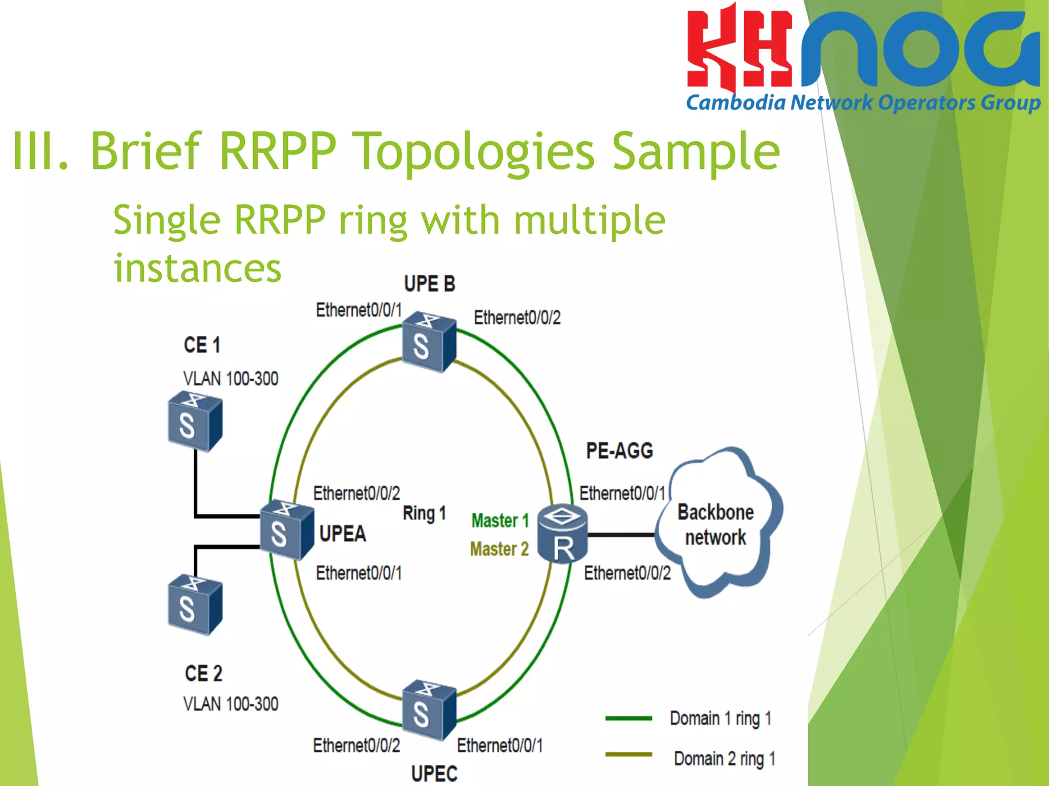
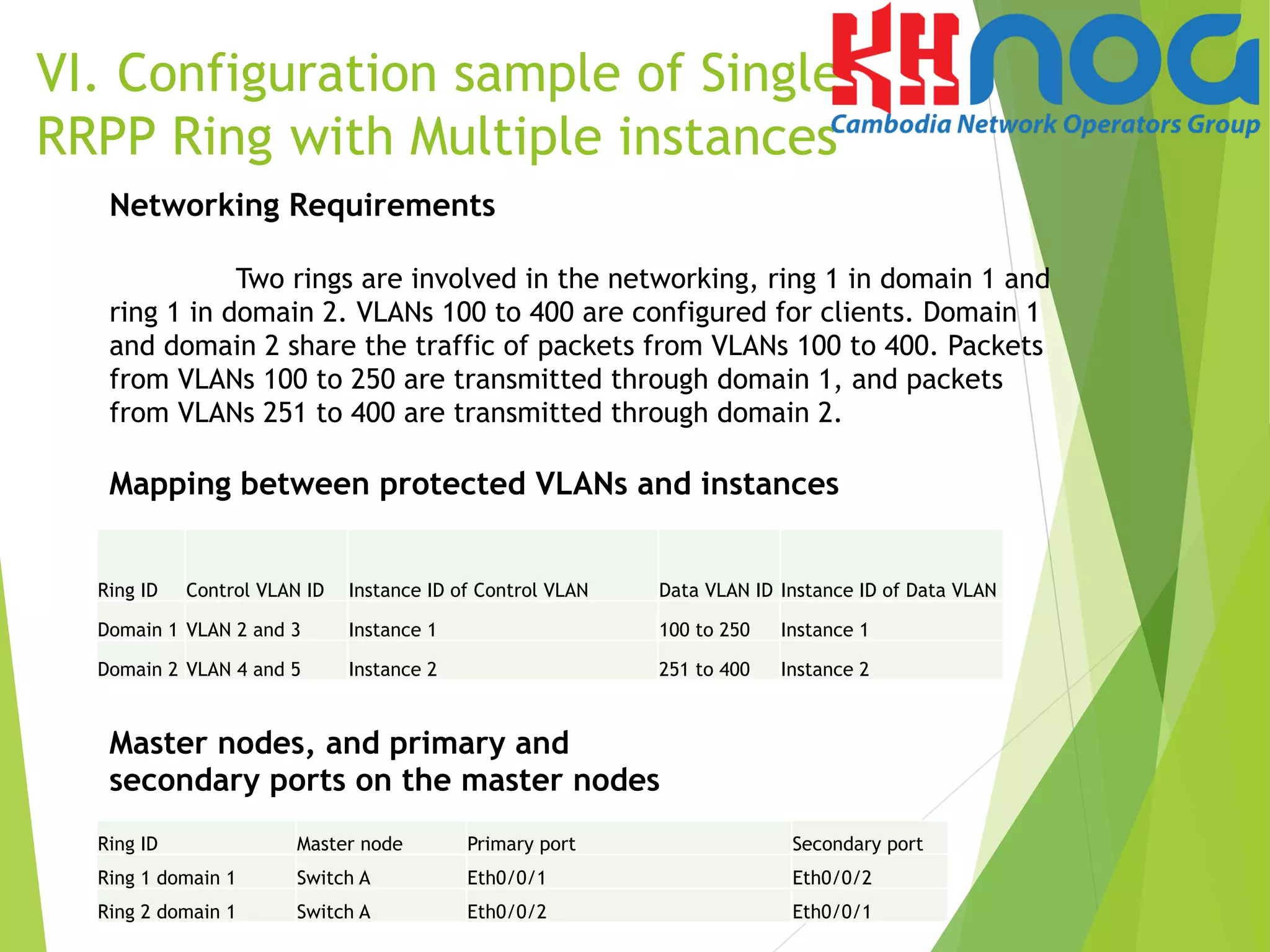
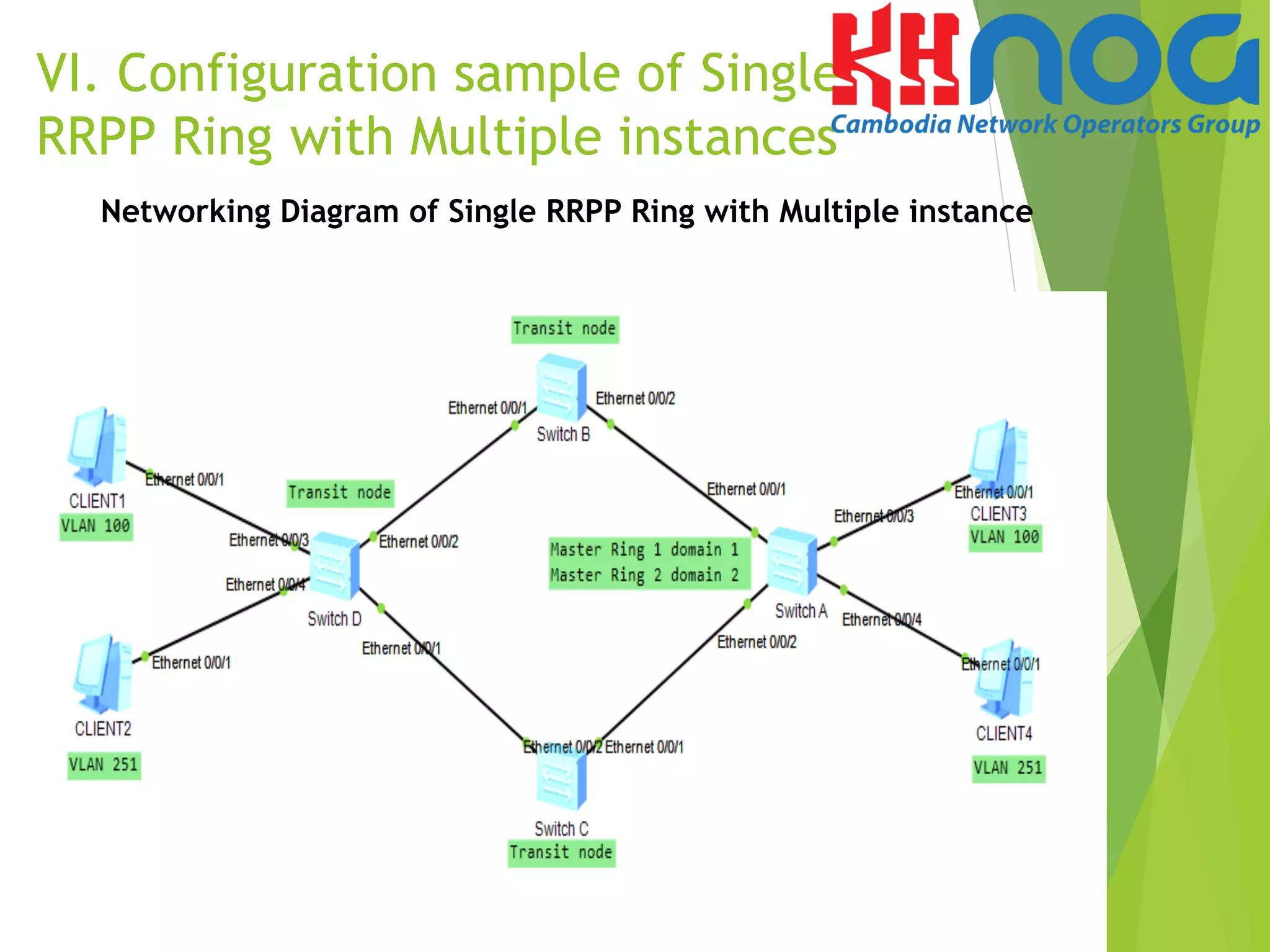
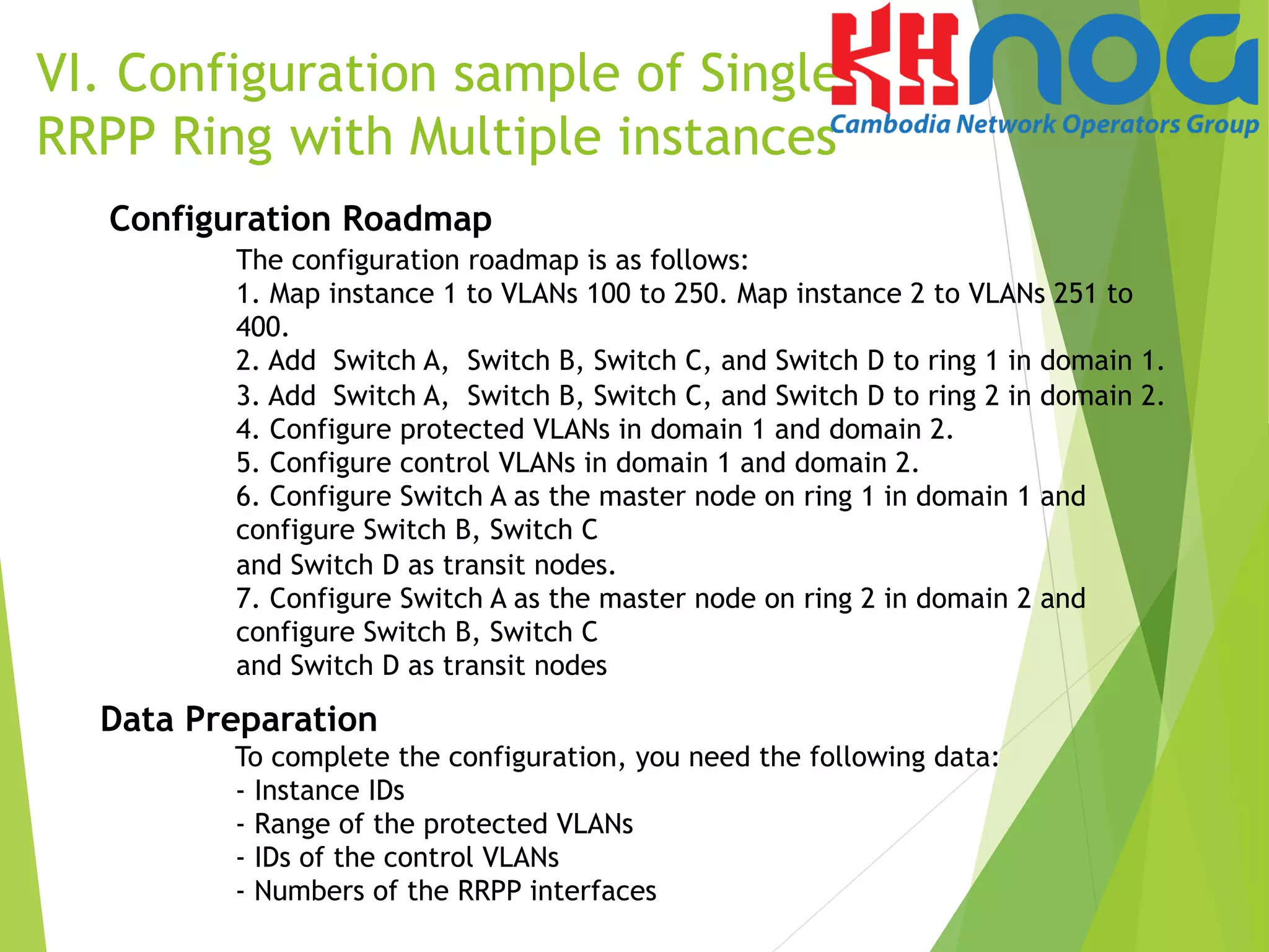
VI. Configuration sample of Single
RRPP Ring with Multiple instances](https://image.slidesharecdn.com/mr-160902015528/75/Rapid-Ring-Protection-Protocol-RRPP-31-2048.jpg)
![# Verify the configuration
Run the display stp region-configuration command on the devices to view the
mapping between instance and VLANs. The displayed information on Switch A is
as follows:
[SwitchA]dis stp region-configuration
Oper configuration
Format selector :0
Region name :4c1fccd111de
Revision level :0
Instance VLANs Mapped
0 1, 6 to 99, 401 to 4094
1 2 to 3, 100 to 250
2 4 to 5, 251 to 400
VI. Configuration sample of Single
RRPP Ring with Multiple instances](https://image.slidesharecdn.com/mr-160902015528/75/Rapid-Ring-Protection-Protocol-RRPP-32-2048.jpg)
![VI. Configuration sample of Single
RRPP Ring with Multiple instances
Step 2 Create an RRPP domain and configure the protected
VLAN the control VLAN.
# Configure the VLANs mapping instance 1 as the protected VLANs in domain 1.
Configure VLAN 2 as the control VLAN.
[SwitchA]rrpp domain 1
[SwitchA-rrpp-domain-region1]protected-vlan reference-instance 1
[SwitchA-rrpp-domain-region1]control-vlan 2
# Configure the VLANs mapping instance 2 as the protected VLANs in domain 2.
Configure VLAN 4 as the control VLAN.
[SwitchA]rrpp domain 2
[SwitchA-rrpp-domain-region2]protected-vlan reference-instance 2
[SwitchA-rrpp-domain-region2]control-vlan 4
Note: The configurations of Switch B, Switch C and switch D are the same to the
configuration of Switch A. The detailed configurations are omitted.](https://image.slidesharecdn.com/mr-160902015528/75/Rapid-Ring-Protection-Protocol-RRPP-33-2048.jpg)
![Step 3 Create RRPP Rings.
- Configure Switch A
# Configure Switch A as the master node of ring 1 in domain 1.
Configure Eth 0/0/1 as the primary port and Eth 0/0/2 as the
secondary port.
[SwitchA]rrpp domain 1
[SwitchA-rrpp-domain-region1]ring 1 node-mode master
primary-port Ethernet 0/0/1 secondary-port Ethernet 0/0/2
level 0
[SwitchA-rrpp-domain-region1]ring 1 enable
# Configure Switch A as the master node of ring 2 in domain 2.
Configure Eth 0/0/1 as the primary port and Eth 0/0/2 as the
secondary port.
[SwitchA]rrpp domain 2
[SwitchA-rrpp-domain-region2]ring 2 node-mode master
primary-port Ethernet 0/0/2
secondary-port Ethernet 0/0/1 level 0
[SwitchA-rrpp-domain-region2]ring 2 enable
# Enable RRPP protocol
After configuring an RRPP ring, you need to enable RRPP on each
node on the ring to activate the RRPP ring.
[SwitchA]rrpp enable
VI. Configuration sample of Single
RRPP Ring with Multiple instances](https://image.slidesharecdn.com/mr-160902015528/75/Rapid-Ring-Protection-Protocol-RRPP-34-2048.jpg)
![Step 3 Create RRPP Rings.
- Configure on Switch B, Switch C and Switch D
# Configure Switch B, Switch C and Switch D as the transit node of
ring 1 in domain 1 and specify the primary and secondary port.
[SwitchB]rrpp domain 1
[SwitchB-rrpp-domain-region1]ring 1 node-mode transit primary-
port Ethernet 0/0/1 secondary-port Ethernet 0/0/2 level 0
[SwitchB-rrpp-domain-region1]ring 1 enable
# Configure Switch B, Switch C and Switch D as the transit node of
ring 2 in domain 2 and specify the primary and secondary port.
[SwitchB]rrpp domain 2
[SwitchB-rrpp-domain-region2]ring 2 node-mode transit primary-
port Ethernet 0/0/1 secondary-port Ethernet 0/0/2 level 0
[SwitchB-rrpp-domain-region1]ring 2 enable
# Enable RRPP protocol
After configuring an RRPP ring, you need to enable RRPP on each node on
the ring to activate the RRPP ring.
[SwitchB]rrpp enable
Note: The configurations of Switch C and switch D are the same to the configuration of Switch B.
The detailed configurations are omitted.
VI. Configuration sample of Single
RRPP Ring with Multiple instances](https://image.slidesharecdn.com/mr-160902015528/75/Rapid-Ring-Protection-Protocol-RRPP-35-2048.jpg)
![Step 6 Verify the configuration.
After the configurations are completed and network become stable, run the
following commands to verify the configuration. Run the display rrpp brief command
on Switch-A. The following information is displayed:
SwitchA]dis rrpp brief
Abbreviations for Switch Node Mode :
M - Master , T - Transit , E - Edge , A - Assistant-Edge
RRPP Protocol Status: Enable
RRPP Working Mode: HW
RRPP Linkup Delay Timer: 0 sec (0 sec default)
Number of RRPP Domains: 2
Domain Index : 1
Control VLAN : major 2 sub 3
Protected VLAN : Reference Instance 1
Hello Timer : 1 sec(default is 1 sec) Fail Timer : 6 sec(default is 6 sec)
Ring Ring Node Primary/Common Secondary/Edge Is
ID Level Mode Port Port Enabled
----------------------------------------------------------------------------
1 0 M Ethernet0/0/1 Ethernet0/0/2 Yes
Domain Index : 2
Control VLAN : major 4 sub 5
Protected VLAN : Reference Instance 2
Hello Timer : 1 sec(default is 1 sec) Fail Timer : 6 sec(default is 6 sec)
Ring Ring Node Primary/Common Secondary/Edge Is
ID Level Mode Port Port Enabled
----------------------------------------------------------------------------
2 0 M Ethernet0/0/2 Ethernet0/0/1 Yes](https://image.slidesharecdn.com/mr-160902015528/75/Rapid-Ring-Protection-Protocol-RRPP-36-2048.jpg)
![Step 6 Verify the configuration.
After the configurations are completed and network become stable, run the following
commands to verify the configuration. Run the display rrpp verbose domain 1 command on
Switch-A. The detail information about RRPP domain 1 is displayed as followed:
[SwitchA]dis rrpp verbose
Domain Index : 1
Control VLAN : major 2 sub 3
Protected VLAN : Reference Instance 1
Hello Timer : 1 sec(default is 1 sec) Fail Timer : 6 sec(default is 6 sec)
RRPP Ring : 1
Ring Level : 0
Node Mode : Master
Ring State : Complete
Is Enabled : Enable Is Active: Yes
Primary port : Ethernet0/0/1 Port status: UP
Secondary port : Ethernet0/0/2 Port status: BLOCKED
Domain Index : 2
Control VLAN : major 4 sub 5
Protected VLAN : Reference Instance 2
Hello Timer : 1 sec(default is 1 sec) Fail Timer : 6 sec(default is 6 sec)
RRPP Ring : 2
Ring Level : 0
Node Mode : Master
Ring State : Complete
Is Enabled : Enable Is Active: Yes
Primary port : Ethernet0/0/2 Port status: UP
Secondary port : Ethernet0/0/1 Port status: BLOCKED](https://image.slidesharecdn.com/mr-160902015528/75/Rapid-Ring-Protection-Protocol-RRPP-37-2048.jpg)


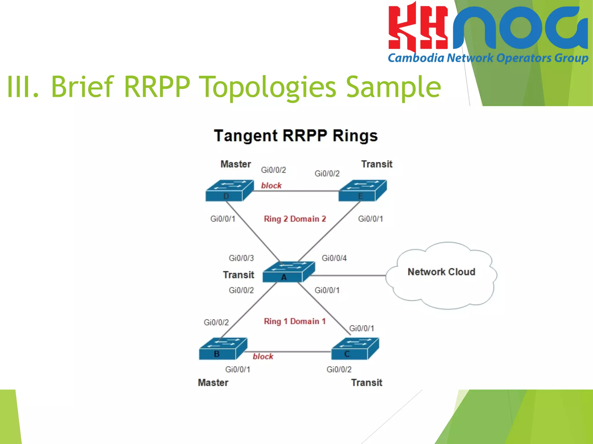
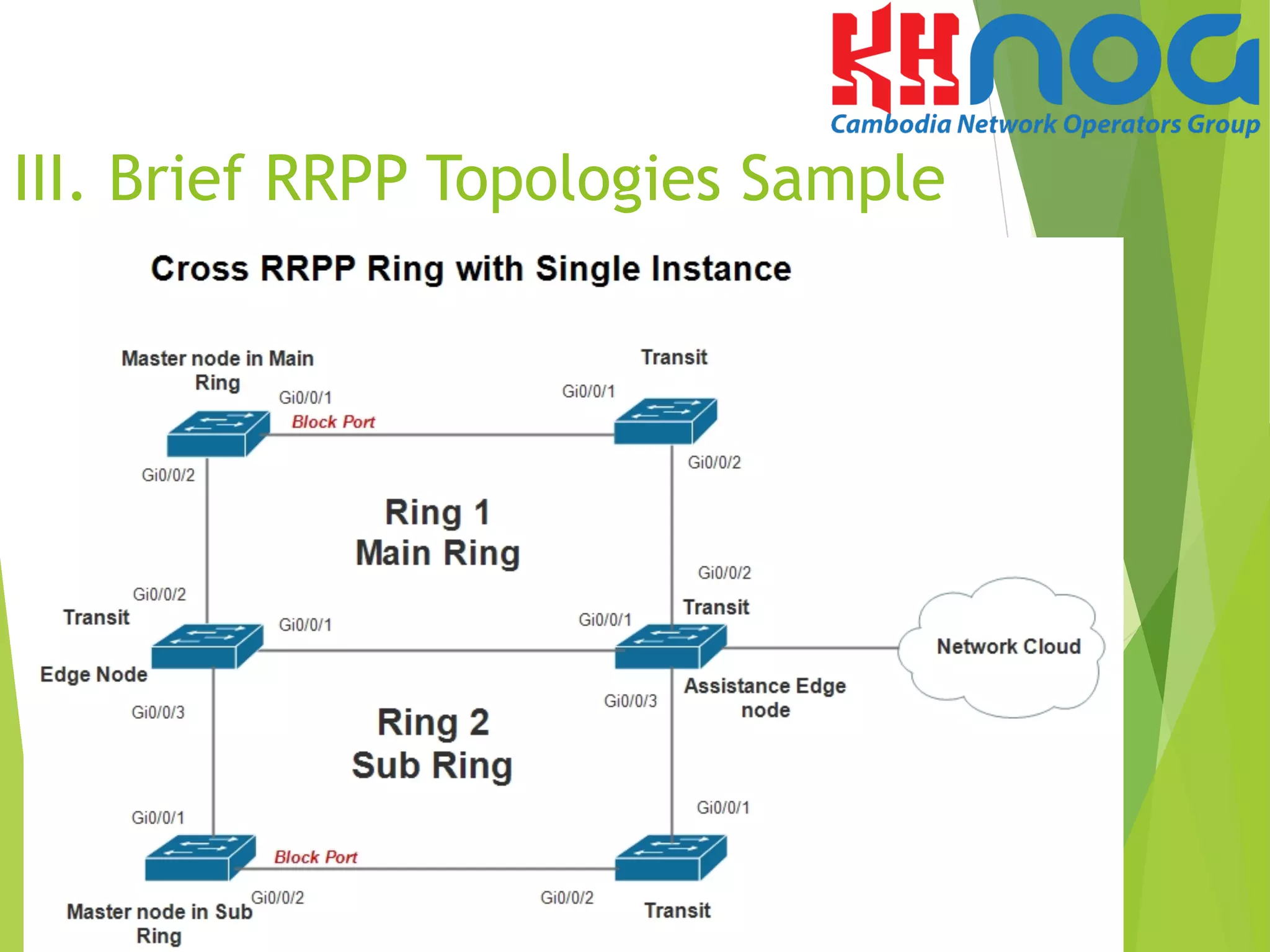
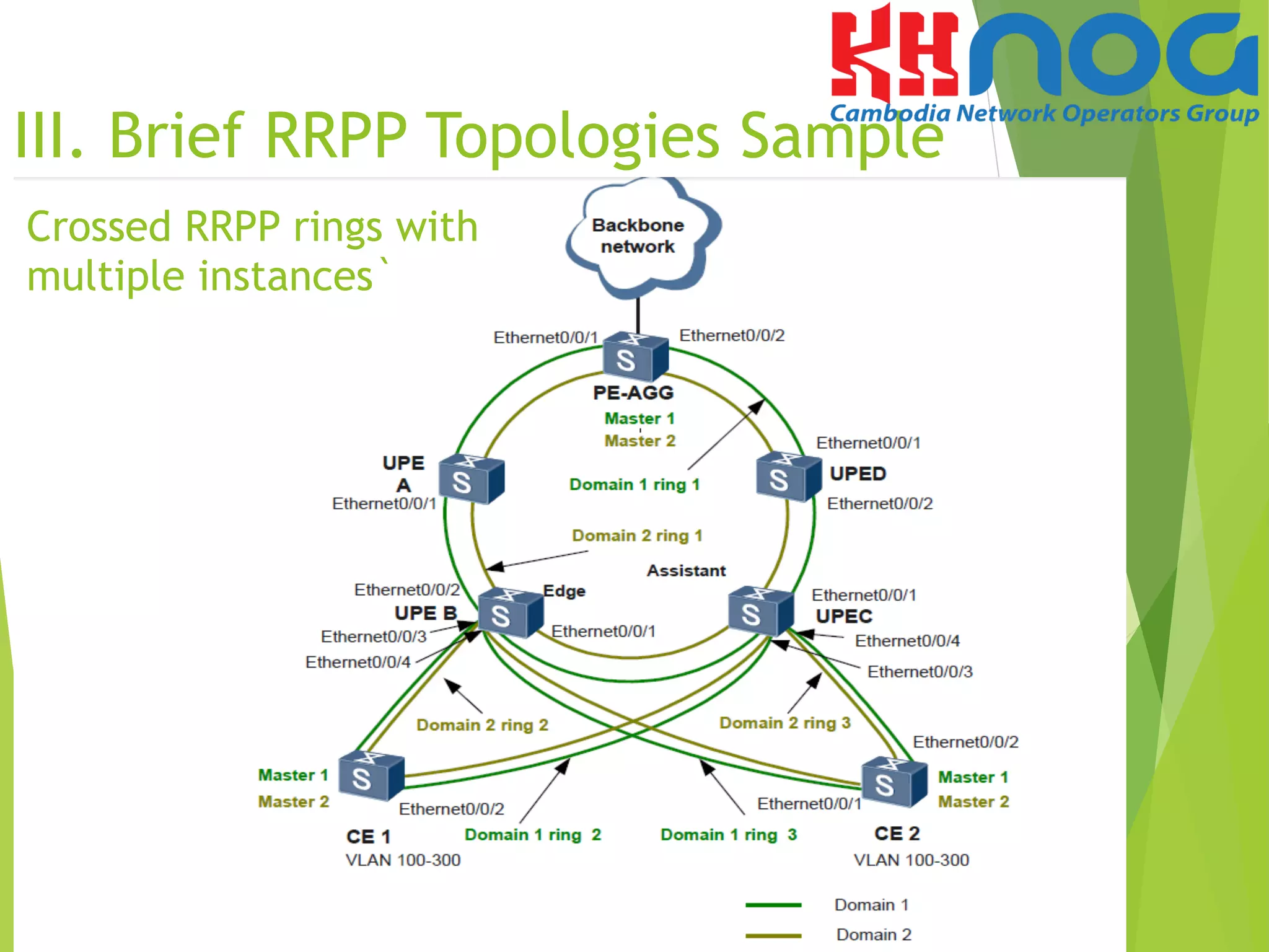
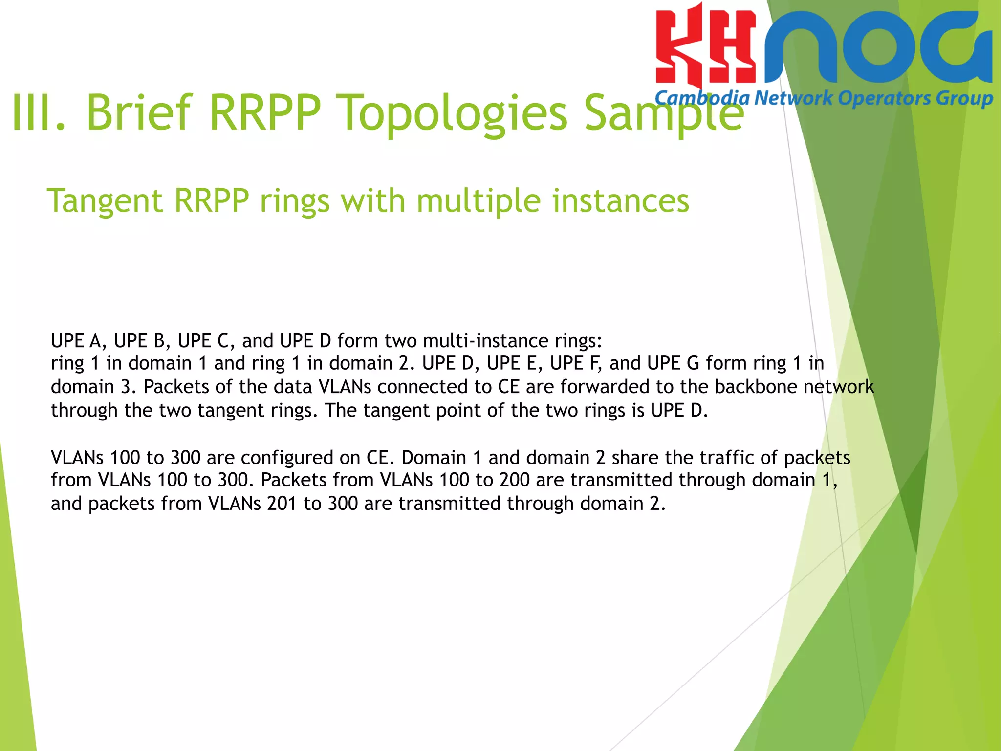
Rapid Ring Protection Protocol (RRPP) is a proprietary Huawei link layer protocol used to prevent broadcast storms on Ethernet rings. It provides fast convergence of less than 50ms when links fail. RRPP supports various topologies including single, crossed, and tangent rings. It also supports multiple instances on a single ring for load balancing. The document provides an overview of RRPP, compares it to other ring protocols, describes its features and functions, and provides sample configurations for a single RRPP ring with multiple instances.


![Vibe Coding vs. Spec-Driven Development [Free Meetup]](https://cdn.slidesharecdn.com/ss_thumbnails/vibecodingvsspecdrivendevelopment-251209105622-43f455e7-thumbnail.jpg?width=640&height=640&fit=bounds)


![Coded Agents – with UiPath SDK + LangGraph [Virtual Hands-on Workshop]](https://cdn.slidesharecdn.com/ss_thumbnails/codedagentsdeck-251215155422-5497c599-thumbnail.jpg?width=640&height=640&fit=bounds)


