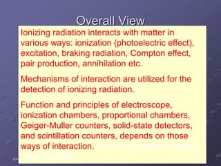
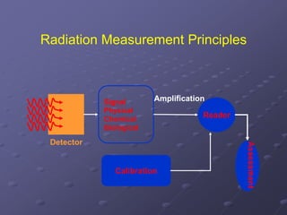
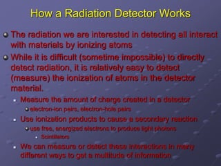
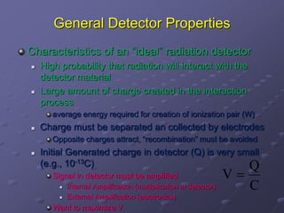
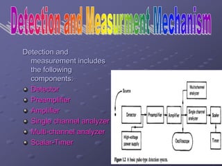
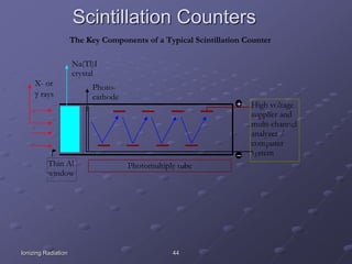
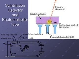
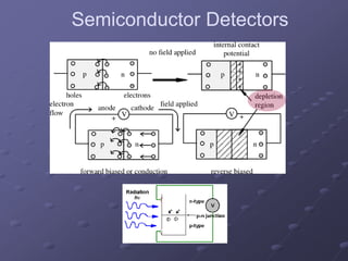
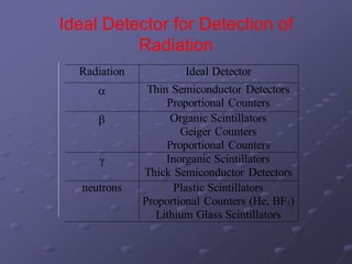
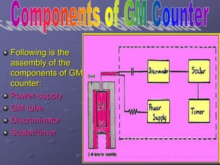
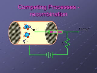
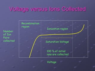
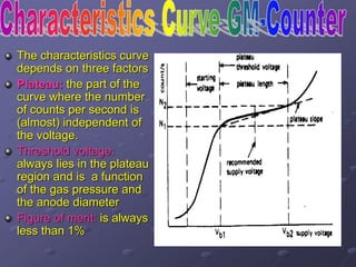
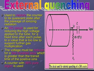
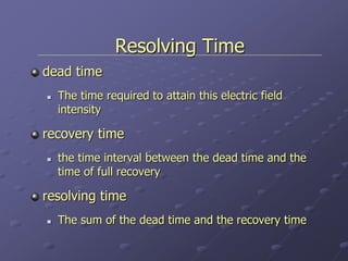
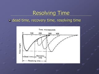
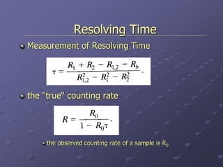
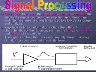
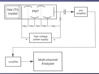
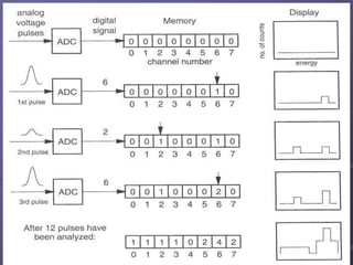
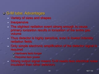
In The Name Of ALLAH
The Most Merciful & Benevolent Beyond Reckoning
What Is Radiation
7
The Electromagnetic Spectrum
Waveform of Radiation
NONIONIZING IONIZING
Radio
Microwaves
Infrared
Visible light
Ultraviolet
X-rays
Gamma rays
Radiation is the emission and transmission
of energy through space or through a
material medium.
Radiation can be in the form of sub-atomic
particles (protons, neutrons and electrons)
or electromagnetic waves
9
What is Radiation?
Form of energy
Emitted by nucleus of atom or orbital electron
Released in form of electromagnetic waves
or particles
 Ionizing Radiation (IR) causes ions to be
produced when radiation is absorbed in
matter
 Non-Ionizing radiation (NIR) refers to
radiation energy that, instead of producing
charged ions, when passing through
matter, has sufficient energy only for
excitation.
Natural Background Radiation
Man-Made Radiation
Summary of Radiation
Why We Measure
Personal Dosimetry vs Regulatory
requirements
Classification of safe and dangerous
zones
Safety vs Protective measures
Quality control and Quality assurance
Data consistancy and standardization
Importance of Radiation in Daily
Life
Medicine: Radiology, Radiation Therapy
Power Production and Space Exploration
In Agriculture to improve variety & yield
production
Weapons of mass destruction
Industrial applications: Gauges,
Radiography, Mineral exploration
Why is Radiation Detection
Difficult?
Can’t see it
Can’t smell it
Can’t hear it
Can’t feel it
Can’t taste it
We take advantage of the fact that radiation
produces ionized pairs to try to create an
electrical signal
How Do I Protect Myself?
Reducing the dose from any source radiation
exposure involves the use of three protective
measures:
– TIME
– DISTANCE
– SHIELDING
Time
− The amount of
exposure an individual
accumulates is directly
proportional to the time
of exposure
− Keep handling time to
a minimum
Distance
− The relationship
between distance and
exposure follows the
inverse square law.
The intensity of the
radiation exposure
decreases in
proportion to the
inverse of the distance
squared
− Dose2 = Dose1 x (d1/d2)2
Shielding
− To shield against beta
emissions, use plexiglass
to decrease the
production of
bremsstrahlung radiation.
− If necessary, supplement
with lead after the
plexiglass
− To shield against gamma
and x-rays, use lead,
leaded glass or leaded
plastic
Self Protection Measures
1st Avoid exposure and contamination
 Detect radiation exposure
 Back away when too high
2nd Use Personal Protective Equipment
(PPE)
3rd Decontaminate yourself
Simplified Radiation PPE
Protect your respiratory tract
 Respirator, surgical mask, etc.
Protect your skin
 Gloves!
 Outer clothing
 Chemical suit is not always needed
Self Decontamination
Wash it off
 Hand washing
 Tepid water, mild soap
 No scrubbing
If showering, use shampoo
Remove and launder
clothing
Monitor after decon
25
Purple and yellow
Radiation Symbol
ALARA
Goal of exposure management:
keep radiation exposures to a level
As Low As Reasonably Achievable
(ALARA)
27
Radiation Units
Units of radiation include
• Curie
- measures activity as the number of atoms
that decay in 1 second.
• rad (radiation absorbed dose)
- measures the radiation absorbed by the
tissues of the body.
• rem (radiation equivalent)
- measures the biological damage caused
28
Units of Radiation Measurement
RADIATION DETECTORS
• Instruments used in the practice of health &
Medical physics serve a wide variety of
purposes
• one finds instruments designed specifically for
the measurement of a certain type of
radiation, such as Alpha Particles, Beta
Particles low-energy X-rays, high-energy
gamma rays. fast neutrons, and so on
• The basic requirement of any such
instrument is that its detector interact with
the radiation in such a manner that the
magnitude of the instrument's response
like development of current or voltage
pulse, Charging and Discharging of
Capacitors is proportional to the radiation
effect or radiation property being
measured
Ionizing Radiation 31
Overall View
Ionizing radiation interacts with matter in
various ways: ionization (photoelectric effect),
excitation, braking radiation, Compton effect,
pair production, annihilation etc.
Mechanisms of interaction are utilized for the
detection of ionizing radiation.
Function and principles of electroscope,
ionization chambers, proportional chambers,
Geiger-Muller counters, solid-state detectors,
and scintillation counters, depends on those
ways of interaction. and cloud chambers have
been describe.
Radiation Measurement Principles
Detector
Signal
Physical
Chemical
Biological
Reader
Calibration
Assessment
Amplification
How a Radiation Detector Works
The radiation we are interested in detecting all interact
with materials by ionizing atoms
While it is difficult (sometime impossible) to directly
detect radiation, it is relatively easy to detect
(measure) the ionization of atoms in the detector
material.
 Measure the amount of charge created in a detector
electron-ion pairs, electron-hole pairs
 Use ionization products to cause a secondary reaction
use free, energized electrons to produce light photons
 Scintillators
 We can measure or detect these interactions in many
different ways to get a multitude of information
General Detector Properties
Characteristics of an “ideal” radiation detector
 High probability that radiation will interact with the
detector material
 Large amount of charge created in the interaction
process
average energy required for creation of ionization pair (W)
 Charge must be separated an collected by electrodes
Opposite charges attract, “recombination” must be avoided
 Initial Generated charge in detector (Q) is very small
(e.g., 10-13C)
Signal in detector must be amplified
 Internal Amplification (multiplication in detector)
 External Amplification (electronics)
Want to maximize V
C
Q
V 
Detection and
measurement includes
the following
components:
Detector
Preamplifier
Amplifier
Single channel analyzer
Multi-channel analyzer
Scalar-Timer
a detector produces a signal for every particle
entering in it.
Every detector works by using some interaction
of particles with matter.
Use characteristic effects from interaction of
radiation with matter to detect, identify and/or
measure properties of radiation.
Respond to radiation by producing various
physical effects
Detection Processes
Ionization: Gas/Liquid chambers and
Semiconductor Detectors
Scintillation: Scintillation counters and TLDs
Sparking: Sparking chamber
Blackening of photographic film: Nuclear
Emulsion detector and Film dosimetry
Bubbling/Clouding of supersaturated
liquids/vapors: Cloud Chambers and Bubble
Chambers
Detection Processes
Physical Changes: NMR Dosimetry and
SSNTDs
Themodynamical Changes: Calorimetric
Dosimetry
Activation: Neutron Activation Detectors
Biological Changes: ESR Detectors and
Biosensors
Following is the list of most common types of
detectors:
Gas-filled counters
ionization chamber
Proportional Counter
Geiger-Muller counter
Scintillation detectors
Semiconductor detectors
Gas Detectors
Most common form of radiation detector
 Relatively simple construction
Suspended wire or electrode plates in a container
Can be made in very large volumes (m3)
 Mainly used to detect b-particles and neutrons
Ease of use
 Mainly used for counting purposes only
High value for W (20-40 eV / ion pair)
Can give you some energy information
Inert fill gases (Ar, Xe, He)
Low efficiency of detection
 Can increase pressure to increase efficiency
 g-rays are virtually invisible
Ionization Chambers
Two electric plates
surrounded by a metal
case
Electric Field (E=V/D) is
applied across
electrodes
Electric Field is low
 only original ion pairs
created by radiation are
collected
 Signal is very small
Can get some energy
information
 Resolution is poor due to
statistics, electronic noise,
and microphonics
Good for detecting heavy charged
particles, betas
Proportional Counters
Wire suspended in a tube
 Can obtain much higher electric
field
 E  1/r
Near wire, E is high
Electrons are energized to the
point that they can ionize
other atoms
 Detector signal is much larger
than ion chamber
Can still measure energy
 Same resolution limits as ion
chamber
Used to detect alphas, betas,
and neutrons
Scintillator Detectors
Voltage is not applied to these types of
detectors
Radiation interactions result in the creation of
light photons
 Goal is to measure the amount of light created
 Light created is proportion to radiation energy
To measure energy, need to convert light to
electrical signal
 Photomultiplier tube
 Photodiode
Two general types
 Organic
 Inorganic
} light  electrons
Ionizing Radiation 44
Scintillation Counters
The Key Components of a Typical Scintillation Counter
High voltage
supplier and
multi-channel
analyzer /
computer
system
Photomultiply tube
Photo-
cathode
Na(Tl)I
crystal
Thin Al
window
X- or
g rays
Ionizing Radiation 45
Scintillation
Detector
and
Photomultiplier
tube
Ionizing Radiation 46
Fluorescence Screens
Fluorescence materials absorb invisible energy and emit visible light.
J.J. Thomson used fluorescence screens to see electron tracks in cathode ray
tubes. Electrons strike fluorescence screens on computer monitors and TV
sets give dots of visible light.
Röntgen saw the shadow of his skeleton on fluorescence screens.
Rutherford observed alpha particle on scintillation material zinc sulfide.
Fluorescence screens are used to photograph X-ray images using films
sensitive visible light.
Semiconductor Detector
A semiconductor detector acts as a solid-state
ionization chamber
The operation of a semiconductor radiation
detector depends on its having either an
excess of electrons or an excess of holes.
A semiconductor with an excess of electrons
is called an n-type semiconductor, while one
with an excess of holes is called a p-type
semiconductor
Semiconductor Detectors
Ideal Detector for Detection of
Radiation
Radiation Ideal Detector
 Thin Semiconductor Detectors
Proportional Counters
b Organic Scintillators
Geiger Counters
Proportional Counters
g Inorganic Scintillators
Thick Semiconductor Detectors
neutrons Plastic Scintillators
Proportional Counters (He, BF3)
Lithium Glass Scintillators
one of the oldest devices used to detect and
measure ionizing (nuclear) radiation
Named for Hans Geiger who invented the device
in 1908, and Walther Müller who collaborated
with Geiger in developing it further in 1928
one of the most sensitive, especially for the low
radiation levels typically found in most situations.
Following is the
assembly of the
components of GM
counter:
Power-supply
GM tube
Discriminator
Scaler/timer
GM Counter Assembly
Variable voltage source
Gas-filled counting chamber
Two coaxial electrodes well insulated from
each other
Electron-pairs
 produced by radiation in fill gas
 move under influence of electric field
 produce measurable current on electrodes, or
 transformed into pulse
GM Tube In Action
wall
fill gas
R
Output
Aor
Anode (+)
Cathode (-)
End
window
Or wall
Indirect Ionization Process
wall
Incident gamma photon
Direct Ionization Process
wall
Incident
charged
particle
e -
e -
e -
e -
e -
e -e -
e -
beta (β-)
Competing Processes -
recombination
R
Outpute -
e -
+
+
Voltage versus Ions Collected
Voltage
Number
of Ion
Pairs
collected
Ionization region
Saturation Voltage
100 % of initial
ions are collected
Recombination
region
The characteristics curve
depends on three factors
Plateau: the part of the
curve where the number
of counts per second is
(almost) independent of
the voltage.
Threshold voltage:
always lies in the plateau
region and is a function
of the gas pressure and
the anode diameter
Figure of merit: is always
less than 1%
A process causing the discharge to
terminate
Two methods used for quenching are:
External quenching
Internal quenching
Used to restore the counter
to its quiescent state after
the passage of ionizing
radiation
An RC circuit is used for
reducing the high voltage
applied to the tube, for a
fixed time after each pulse,
to a value that is too low to
support further gas
multiplication
The voltage must be reduced
for a few hundred secs which
is greater than the transit
time of the positive ions
A counter with 98% pure
argon is used
The advantage of external quenching is
that it gives long life time to GM tube
The disadvantage is that it has long
recovery time
The quenching agent gas in the Geiger counter
stops the flow of electrical current after a few
microseconds.
the quenching gas is of low ionization potential
(halogens or organic vapors)
Halogens are preferably used because it
increases the life of GM tube
Organic quenched tubes usually have a flatter
plateau than halogen quenched tubes
The purpose of the quenching additive to the
gas is to effectively absorb UV-photons emitted
from the electrodes when the ions produced in
the multiplication process impact on the
electrodes.
Such photons otherwise liberate secondary
electrons (via the photo-electric effect) which
may initiate the avalanche process all over
again, thereby leading to catastrophic
breakdown of the tube (i.e. a spark).
Device serving as pulse height selector
able to make selection from output analogical
pulses, rejecting the impulses with voltage
amplitude inferior to a certain threshold voltage
Threshold voltage should neither too low nor too
high to avoid noise and data-loss respectively
Its function is double:
To eliminate the noise
To provide a standard shaped pulse to scaler
Scalar: counts the number of pulses
Timer: measures the length of counting
time in a given measurement
Collectively used to:
Make measurement of pulses for a preset
length of time (set on timer) recording the
number of counts by the scaler
Determine the count-rate by measuring
duration with timer for a preset number of
counts
Geiger-Muller Counter
Resolving Time
The negative ions, being electrons, move very rapidly
and are soon collected, while the massive positive
ions are relatively slow-moving and therefore travel
for a relatively long period of time before being
collected
These slow-moving positive ions form a sheath
around the positively charged anode, thereby greatly
decreasing the electric field intensity around the
anode and making it impossible to initiate an
avalanche by another ionizing particle. As the positive
ion sheath moves toward the cathode, the electric
field intensity increases, until a point is reached when
another avalanche could be started
Resolving Time
dead time
 The time required to attain this electric field
intensity
recovery time
 the time interval between the dead time and the
time of full recovery
resolving time
 The sum of the dead time and the recovery time
Resolving Time
dead time, recovery time, resolving time
Resolving Time
Measurement of Resolving Time
the "true“ counting rate
the observed counting rate of a sample is R0
Objective: to extract the amplitude or timing information the
electrical signal is coupled to an amplifier, sent through gain
and filtering stages, and finally digitized to allow data storage
and analysis.
amplitude or timing information include the different
characteristics of the radiation, such as the type, the intensity
and energy of the radiation
The signal can be either processed entirely through analog
circuit or can be converted into digital form
The signal can be a continuously varying
signal
a sequence of pulses, occurring
periodically
at known times
randomly
All of these affect the choice of signal
processing techniques.
First steps in signal processing:
Formation of the signal in the detector
(sensor)
Coupling the sensor to the amplifier
Detectors use either
direct detection or
indirect detection
The detector pulse has a very low amplitude &
time duration i.e. narrow band width
To extract any kind of information requires
amplification of detector signal
Preamplifier is a simple and efficient amplifier
directly connected to detector
A preamplifier, in effect, acts as a capacitance
terminator thus preventing deterioration of
detector.
Matches the high electric impedance of detector
with low impedance of the coaxial cable
connected to subsequent signal processing
circuit
Basically plays a role as an impedance matcher
between the detector and the rest of the circuit
The function is to amplify the pulses from
detector via a preamplifier
Also used to shape a pulse for further
detection
High-voltage power supply typically
provides 800 to 1,200 volts to the PMT
 Raising voltage increases magnitude of
voltage pulses from PMT
Preamp connected to PMT using very
short cable
 Amplifies voltage pulses to minimize distortion
and attenuation of signal during transmission
to remainder of system
SCA Contd.
Amplifier further amplifies the pulses and
modifies their shapes – gain typically adjustable
SCA allows user to set two voltage levels, a
lower level and an upper level
 If input pulse has voltage within this range, output
from SCA is a single logic pulse (fixed amplitude and
duration)
Counter counts the logic pulses from the SCA
for a time interval set by the timer
SCA energy modes
LL/UL mode – one knob directly sets the lower
level and the other sets the upper level
Window mode – one knob (often labeled E) sets
the midpoint of the range of acceptable pulse
heights and the other knob (often labeled E or
window) sets a range of voltages around this
value.
 Lower-level voltage is E - E/2 and upper-level
voltage is E + E/2
An MCA system permits an energy spectrum to
be automatically acquired much more quickly
and easily than does a SCA system
The detector, HV power supply, preamp, and
amplifier are the same as for SCA systems
The MCA consists of an analog-to-digital
converter, a memory containing many storage
locations called channels, control circuitry, a
timer, and a display
G-M tube: Advantages
 Variety of sizes and shapes
 Inexpensive
 The slightest radiation event strong enough to cause
primary ionization results in ionization of the entire gas
volume
 Thus detector is highly sensitive, even in lowest intensity
radiation fields
 Only simple electronic amplification of the detector signal is
required
Hardware lasts longer
Requires less power
 Strong output signal means G-M needs less electrical noise
insulation than other detectors
NET 13088
G-M tube: Disadvantages
 Incapable of discerning between type and energy
of the radiation event
 Only counts events and yields output in events per
unit time or dose rate
 A beta particle or gamma ray, high or low energy,
represents one event counted
 Only capable of detecting fields to some upper limit
of intensity
Limited to lower intensity fields due to detector dead
time
NET 13089
Personnel Monitor Devices
The most common monitor devices to determine the personal exposure
history are:
Radiation Film Badges
Pocket Dosimeter
Radiation film badges are composed of two pieces of film,
covered by light tight paper in a compact plastic container. Various
filters in the badge holder allow areas to be restricted to X-ray, g-ray, b-
rays only.
Radiation causes a blackening (silver) of the film material
(mostly a silver bromide emulsion) The sensitivity of the film material is
limited
For g-radiation the sensitivity is in the range of 10 - 1800 mrem.
For b-radiation the sensitivity is in the range of 50 - 1000 mrem.
Special film material is used for neutron monitoring.
The badge is usually not sensitive for  radiation because the
-particles are absorbed in the light-tight paper.
Pocket dosimeter
The pocket dosimeter or pen dosimeter is a common small sized
ion chamber which measures the originated charge by direct collection on a
quartz fiber electroscope.
The U-shaped fiber is close to a U-shaped wire. If the fiber is
charged it will be deflected away from the wire. The position of
deflection is a measure of the accumulated radiation dose.
The dosimeter records total exposure from the initial
charging to the time of reading.
It is an active device as the radiation exposure can be
read immediately as opposed to the passive film badge which is
only read after approximately six months.
Dosimeters, which are also available in high or low ranges, can be in the
form of a badge, pen/tube type, or even a digital readout and all measure exposure or
the total accumulated amount of radiation to which you were exposed. (The Civil
Defense pen/tube tube would show a reading like below when looking through it.) It's
also similar to the odometer of a car; where both measure an accumulation of units.
The dosimeter will indicate a certain total number of R or mR exposure received, just
as the car odometer will register a certain number of miles traveled.
Thermoluminescence
(TL) is the ability to convert energy from
radiation to a radiation of a different wavelength,
normally in the visible light range.
Two categories
 Fluorescence - emission of light during or immediately
after irradiation
 Not a particularly useful reaction for TLD use
 Phosphorescence - emission of light after the
irradiation period. Delay can be seconds to months.
TLDs use phosphorescence to detect radiation.
Thermoluminescence
Radiation moves electrons into “traps”
Heating moves them out
Energy released is proportional to
radiation
Response is ~ linear
High energy trap data is stored in TLD for
a long time
TL Process
Valence Band (outermost electron shell)
Conduction Band (unfilled shell)
Phosphor atom
Incident
radiation
Electron trap (meta
stable state)
-
TL Process, continued
Valence Band (outermost electron shell)
Conduction Band
Phosphor atom
Thermo luminescent
photon Heat Applied-
Output – Glow Curves
A glow curve is obtained from heating
Light output from TL is not easily interpreted
Multiple peaks result from electrons in "shallow" traps
Peak results as traps are emptied.
Light output drops off as these traps are depleted.
Heating continues
Electrons in deeper traps are released.
Highest peak is typically used to calculate dose
Area under represents the radiation energy deposited in
the TLD
Trap Depths - Equate to Long
Term Stability of Information
Time or temperature
TLD Reader Construction
Power Supply
PMT
DC Amp
Filter
Heated Cup
TL material
To High
Voltage To ground
Recorder or meter
NET 130
Module 5 - Radiation
Detection Principles and
Instruments 103
Crystal retains this energy until heat is applied.
The “trapped” energy is then released in the form of
light, as the atoms of the crystal return to their “ground
state”
The light emitted is then correlated to dose received
Once the TLD has been “read”, memory is cleared
TLD is then available for re-use
NET 130 Module 5 - Radiation Detection Principles and Instruments 103
Thermoluminescent Dosimeter
QUESTIONS?
ANY QUESTION PLEASE?
THANK YOU !!!
Niab 2016

Niab 2016

  • 3.
    In The NameOf ALLAH The Most Merciful & Benevolent Beyond Reckoning
  • 4.
  • 7.
    7 The Electromagnetic Spectrum Waveformof Radiation NONIONIZING IONIZING Radio Microwaves Infrared Visible light Ultraviolet X-rays Gamma rays
  • 8.
    Radiation is theemission and transmission of energy through space or through a material medium. Radiation can be in the form of sub-atomic particles (protons, neutrons and electrons) or electromagnetic waves
  • 9.
    9 What is Radiation? Formof energy Emitted by nucleus of atom or orbital electron Released in form of electromagnetic waves or particles
  • 10.
     Ionizing Radiation(IR) causes ions to be produced when radiation is absorbed in matter  Non-Ionizing radiation (NIR) refers to radiation energy that, instead of producing charged ions, when passing through matter, has sufficient energy only for excitation.
  • 11.
  • 12.
  • 14.
  • 15.
    Why We Measure PersonalDosimetry vs Regulatory requirements Classification of safe and dangerous zones Safety vs Protective measures Quality control and Quality assurance Data consistancy and standardization
  • 16.
    Importance of Radiationin Daily Life Medicine: Radiology, Radiation Therapy Power Production and Space Exploration In Agriculture to improve variety & yield production Weapons of mass destruction Industrial applications: Gauges, Radiography, Mineral exploration
  • 17.
    Why is RadiationDetection Difficult? Can’t see it Can’t smell it Can’t hear it Can’t feel it Can’t taste it We take advantage of the fact that radiation produces ionized pairs to try to create an electrical signal
  • 18.
    How Do IProtect Myself? Reducing the dose from any source radiation exposure involves the use of three protective measures: – TIME – DISTANCE – SHIELDING
  • 19.
    Time − The amountof exposure an individual accumulates is directly proportional to the time of exposure − Keep handling time to a minimum
  • 20.
    Distance − The relationship betweendistance and exposure follows the inverse square law. The intensity of the radiation exposure decreases in proportion to the inverse of the distance squared − Dose2 = Dose1 x (d1/d2)2
  • 21.
    Shielding − To shieldagainst beta emissions, use plexiglass to decrease the production of bremsstrahlung radiation. − If necessary, supplement with lead after the plexiglass − To shield against gamma and x-rays, use lead, leaded glass or leaded plastic
  • 22.
    Self Protection Measures 1stAvoid exposure and contamination  Detect radiation exposure  Back away when too high 2nd Use Personal Protective Equipment (PPE) 3rd Decontaminate yourself
  • 23.
    Simplified Radiation PPE Protectyour respiratory tract  Respirator, surgical mask, etc. Protect your skin  Gloves!  Outer clothing  Chemical suit is not always needed
  • 24.
    Self Decontamination Wash itoff  Hand washing  Tepid water, mild soap  No scrubbing If showering, use shampoo Remove and launder clothing Monitor after decon
  • 25.
  • 26.
    ALARA Goal of exposuremanagement: keep radiation exposures to a level As Low As Reasonably Achievable (ALARA)
  • 27.
    27 Radiation Units Units ofradiation include • Curie - measures activity as the number of atoms that decay in 1 second. • rad (radiation absorbed dose) - measures the radiation absorbed by the tissues of the body. • rem (radiation equivalent) - measures the biological damage caused
  • 28.
  • 29.
    RADIATION DETECTORS • Instrumentsused in the practice of health & Medical physics serve a wide variety of purposes • one finds instruments designed specifically for the measurement of a certain type of radiation, such as Alpha Particles, Beta Particles low-energy X-rays, high-energy gamma rays. fast neutrons, and so on
  • 30.
    • The basicrequirement of any such instrument is that its detector interact with the radiation in such a manner that the magnitude of the instrument's response like development of current or voltage pulse, Charging and Discharging of Capacitors is proportional to the radiation effect or radiation property being measured
  • 31.
    Ionizing Radiation 31 OverallView Ionizing radiation interacts with matter in various ways: ionization (photoelectric effect), excitation, braking radiation, Compton effect, pair production, annihilation etc. Mechanisms of interaction are utilized for the detection of ionizing radiation. Function and principles of electroscope, ionization chambers, proportional chambers, Geiger-Muller counters, solid-state detectors, and scintillation counters, depends on those ways of interaction. and cloud chambers have been describe.
  • 32.
  • 33.
    How a RadiationDetector Works The radiation we are interested in detecting all interact with materials by ionizing atoms While it is difficult (sometime impossible) to directly detect radiation, it is relatively easy to detect (measure) the ionization of atoms in the detector material.  Measure the amount of charge created in a detector electron-ion pairs, electron-hole pairs  Use ionization products to cause a secondary reaction use free, energized electrons to produce light photons  Scintillators  We can measure or detect these interactions in many different ways to get a multitude of information
  • 34.
    General Detector Properties Characteristicsof an “ideal” radiation detector  High probability that radiation will interact with the detector material  Large amount of charge created in the interaction process average energy required for creation of ionization pair (W)  Charge must be separated an collected by electrodes Opposite charges attract, “recombination” must be avoided  Initial Generated charge in detector (Q) is very small (e.g., 10-13C) Signal in detector must be amplified  Internal Amplification (multiplication in detector)  External Amplification (electronics) Want to maximize V C Q V 
  • 35.
    Detection and measurement includes thefollowing components: Detector Preamplifier Amplifier Single channel analyzer Multi-channel analyzer Scalar-Timer
  • 36.
    a detector producesa signal for every particle entering in it. Every detector works by using some interaction of particles with matter. Use characteristic effects from interaction of radiation with matter to detect, identify and/or measure properties of radiation. Respond to radiation by producing various physical effects
  • 37.
    Detection Processes Ionization: Gas/Liquidchambers and Semiconductor Detectors Scintillation: Scintillation counters and TLDs Sparking: Sparking chamber Blackening of photographic film: Nuclear Emulsion detector and Film dosimetry Bubbling/Clouding of supersaturated liquids/vapors: Cloud Chambers and Bubble Chambers
  • 38.
    Detection Processes Physical Changes:NMR Dosimetry and SSNTDs Themodynamical Changes: Calorimetric Dosimetry Activation: Neutron Activation Detectors Biological Changes: ESR Detectors and Biosensors
  • 39.
    Following is thelist of most common types of detectors: Gas-filled counters ionization chamber Proportional Counter Geiger-Muller counter Scintillation detectors Semiconductor detectors
  • 40.
    Gas Detectors Most commonform of radiation detector  Relatively simple construction Suspended wire or electrode plates in a container Can be made in very large volumes (m3)  Mainly used to detect b-particles and neutrons Ease of use  Mainly used for counting purposes only High value for W (20-40 eV / ion pair) Can give you some energy information Inert fill gases (Ar, Xe, He) Low efficiency of detection  Can increase pressure to increase efficiency  g-rays are virtually invisible
  • 41.
    Ionization Chambers Two electricplates surrounded by a metal case Electric Field (E=V/D) is applied across electrodes Electric Field is low  only original ion pairs created by radiation are collected  Signal is very small Can get some energy information  Resolution is poor due to statistics, electronic noise, and microphonics Good for detecting heavy charged particles, betas
  • 42.
    Proportional Counters Wire suspendedin a tube  Can obtain much higher electric field  E  1/r Near wire, E is high Electrons are energized to the point that they can ionize other atoms  Detector signal is much larger than ion chamber Can still measure energy  Same resolution limits as ion chamber Used to detect alphas, betas, and neutrons
  • 43.
    Scintillator Detectors Voltage isnot applied to these types of detectors Radiation interactions result in the creation of light photons  Goal is to measure the amount of light created  Light created is proportion to radiation energy To measure energy, need to convert light to electrical signal  Photomultiplier tube  Photodiode Two general types  Organic  Inorganic } light  electrons
  • 44.
    Ionizing Radiation 44 ScintillationCounters The Key Components of a Typical Scintillation Counter High voltage supplier and multi-channel analyzer / computer system Photomultiply tube Photo- cathode Na(Tl)I crystal Thin Al window X- or g rays
  • 45.
  • 46.
    Ionizing Radiation 46 FluorescenceScreens Fluorescence materials absorb invisible energy and emit visible light. J.J. Thomson used fluorescence screens to see electron tracks in cathode ray tubes. Electrons strike fluorescence screens on computer monitors and TV sets give dots of visible light. Röntgen saw the shadow of his skeleton on fluorescence screens. Rutherford observed alpha particle on scintillation material zinc sulfide. Fluorescence screens are used to photograph X-ray images using films sensitive visible light.
  • 47.
    Semiconductor Detector A semiconductordetector acts as a solid-state ionization chamber The operation of a semiconductor radiation detector depends on its having either an excess of electrons or an excess of holes. A semiconductor with an excess of electrons is called an n-type semiconductor, while one with an excess of holes is called a p-type semiconductor
  • 48.
  • 49.
    Ideal Detector forDetection of Radiation Radiation Ideal Detector  Thin Semiconductor Detectors Proportional Counters b Organic Scintillators Geiger Counters Proportional Counters g Inorganic Scintillators Thick Semiconductor Detectors neutrons Plastic Scintillators Proportional Counters (He, BF3) Lithium Glass Scintillators
  • 50.
    one of theoldest devices used to detect and measure ionizing (nuclear) radiation Named for Hans Geiger who invented the device in 1908, and Walther Müller who collaborated with Geiger in developing it further in 1928 one of the most sensitive, especially for the low radiation levels typically found in most situations.
  • 51.
    Following is the assemblyof the components of GM counter: Power-supply GM tube Discriminator Scaler/timer
  • 52.
    GM Counter Assembly Variablevoltage source Gas-filled counting chamber Two coaxial electrodes well insulated from each other Electron-pairs  produced by radiation in fill gas  move under influence of electric field  produce measurable current on electrodes, or  transformed into pulse
  • 53.
    GM Tube InAction wall fill gas R Output Aor Anode (+) Cathode (-) End window Or wall
  • 54.
  • 55.
    Direct Ionization Process wall Incident charged particle e- e - e - e - e - e -e - e - beta (β-)
  • 56.
  • 57.
    Voltage versus IonsCollected Voltage Number of Ion Pairs collected Ionization region Saturation Voltage 100 % of initial ions are collected Recombination region
  • 58.
    The characteristics curve dependson three factors Plateau: the part of the curve where the number of counts per second is (almost) independent of the voltage. Threshold voltage: always lies in the plateau region and is a function of the gas pressure and the anode diameter Figure of merit: is always less than 1%
  • 59.
    A process causingthe discharge to terminate Two methods used for quenching are: External quenching Internal quenching
  • 60.
    Used to restorethe counter to its quiescent state after the passage of ionizing radiation An RC circuit is used for reducing the high voltage applied to the tube, for a fixed time after each pulse, to a value that is too low to support further gas multiplication The voltage must be reduced for a few hundred secs which is greater than the transit time of the positive ions A counter with 98% pure argon is used
  • 61.
    The advantage ofexternal quenching is that it gives long life time to GM tube The disadvantage is that it has long recovery time
  • 62.
    The quenching agentgas in the Geiger counter stops the flow of electrical current after a few microseconds. the quenching gas is of low ionization potential (halogens or organic vapors) Halogens are preferably used because it increases the life of GM tube Organic quenched tubes usually have a flatter plateau than halogen quenched tubes
  • 63.
    The purpose ofthe quenching additive to the gas is to effectively absorb UV-photons emitted from the electrodes when the ions produced in the multiplication process impact on the electrodes. Such photons otherwise liberate secondary electrons (via the photo-electric effect) which may initiate the avalanche process all over again, thereby leading to catastrophic breakdown of the tube (i.e. a spark).
  • 64.
    Device serving aspulse height selector able to make selection from output analogical pulses, rejecting the impulses with voltage amplitude inferior to a certain threshold voltage Threshold voltage should neither too low nor too high to avoid noise and data-loss respectively Its function is double: To eliminate the noise To provide a standard shaped pulse to scaler
  • 66.
    Scalar: counts thenumber of pulses Timer: measures the length of counting time in a given measurement Collectively used to: Make measurement of pulses for a preset length of time (set on timer) recording the number of counts by the scaler Determine the count-rate by measuring duration with timer for a preset number of counts
  • 67.
  • 68.
    Resolving Time The negativeions, being electrons, move very rapidly and are soon collected, while the massive positive ions are relatively slow-moving and therefore travel for a relatively long period of time before being collected These slow-moving positive ions form a sheath around the positively charged anode, thereby greatly decreasing the electric field intensity around the anode and making it impossible to initiate an avalanche by another ionizing particle. As the positive ion sheath moves toward the cathode, the electric field intensity increases, until a point is reached when another avalanche could be started
  • 69.
    Resolving Time dead time The time required to attain this electric field intensity recovery time  the time interval between the dead time and the time of full recovery resolving time  The sum of the dead time and the recovery time
  • 70.
    Resolving Time dead time,recovery time, resolving time
  • 71.
    Resolving Time Measurement ofResolving Time the "true“ counting rate the observed counting rate of a sample is R0
  • 72.
    Objective: to extractthe amplitude or timing information the electrical signal is coupled to an amplifier, sent through gain and filtering stages, and finally digitized to allow data storage and analysis. amplitude or timing information include the different characteristics of the radiation, such as the type, the intensity and energy of the radiation The signal can be either processed entirely through analog circuit or can be converted into digital form
  • 73.
    The signal canbe a continuously varying signal a sequence of pulses, occurring periodically at known times randomly All of these affect the choice of signal processing techniques.
  • 74.
    First steps insignal processing: Formation of the signal in the detector (sensor) Coupling the sensor to the amplifier Detectors use either direct detection or indirect detection
  • 75.
    The detector pulsehas a very low amplitude & time duration i.e. narrow band width To extract any kind of information requires amplification of detector signal Preamplifier is a simple and efficient amplifier directly connected to detector
  • 76.
    A preamplifier, ineffect, acts as a capacitance terminator thus preventing deterioration of detector. Matches the high electric impedance of detector with low impedance of the coaxial cable connected to subsequent signal processing circuit Basically plays a role as an impedance matcher between the detector and the rest of the circuit
  • 77.
    The function isto amplify the pulses from detector via a preamplifier Also used to shape a pulse for further detection
  • 78.
    High-voltage power supplytypically provides 800 to 1,200 volts to the PMT  Raising voltage increases magnitude of voltage pulses from PMT Preamp connected to PMT using very short cable  Amplifies voltage pulses to minimize distortion and attenuation of signal during transmission to remainder of system
  • 80.
    SCA Contd. Amplifier furtheramplifies the pulses and modifies their shapes – gain typically adjustable SCA allows user to set two voltage levels, a lower level and an upper level  If input pulse has voltage within this range, output from SCA is a single logic pulse (fixed amplitude and duration) Counter counts the logic pulses from the SCA for a time interval set by the timer
  • 82.
    SCA energy modes LL/ULmode – one knob directly sets the lower level and the other sets the upper level Window mode – one knob (often labeled E) sets the midpoint of the range of acceptable pulse heights and the other knob (often labeled E or window) sets a range of voltages around this value.  Lower-level voltage is E - E/2 and upper-level voltage is E + E/2
  • 84.
    An MCA systempermits an energy spectrum to be automatically acquired much more quickly and easily than does a SCA system The detector, HV power supply, preamp, and amplifier are the same as for SCA systems The MCA consists of an analog-to-digital converter, a memory containing many storage locations called channels, control circuitry, a timer, and a display
  • 88.
    G-M tube: Advantages Variety of sizes and shapes  Inexpensive  The slightest radiation event strong enough to cause primary ionization results in ionization of the entire gas volume  Thus detector is highly sensitive, even in lowest intensity radiation fields  Only simple electronic amplification of the detector signal is required Hardware lasts longer Requires less power  Strong output signal means G-M needs less electrical noise insulation than other detectors NET 13088
  • 89.
    G-M tube: Disadvantages Incapable of discerning between type and energy of the radiation event  Only counts events and yields output in events per unit time or dose rate  A beta particle or gamma ray, high or low energy, represents one event counted  Only capable of detecting fields to some upper limit of intensity Limited to lower intensity fields due to detector dead time NET 13089
  • 90.
    Personnel Monitor Devices Themost common monitor devices to determine the personal exposure history are: Radiation Film Badges Pocket Dosimeter
  • 91.
    Radiation film badgesare composed of two pieces of film, covered by light tight paper in a compact plastic container. Various filters in the badge holder allow areas to be restricted to X-ray, g-ray, b- rays only. Radiation causes a blackening (silver) of the film material (mostly a silver bromide emulsion) The sensitivity of the film material is limited For g-radiation the sensitivity is in the range of 10 - 1800 mrem. For b-radiation the sensitivity is in the range of 50 - 1000 mrem. Special film material is used for neutron monitoring. The badge is usually not sensitive for  radiation because the -particles are absorbed in the light-tight paper.
  • 92.
    Pocket dosimeter The pocketdosimeter or pen dosimeter is a common small sized ion chamber which measures the originated charge by direct collection on a quartz fiber electroscope. The U-shaped fiber is close to a U-shaped wire. If the fiber is charged it will be deflected away from the wire. The position of deflection is a measure of the accumulated radiation dose.
  • 93.
    The dosimeter recordstotal exposure from the initial charging to the time of reading. It is an active device as the radiation exposure can be read immediately as opposed to the passive film badge which is only read after approximately six months.
  • 94.
    Dosimeters, which arealso available in high or low ranges, can be in the form of a badge, pen/tube type, or even a digital readout and all measure exposure or the total accumulated amount of radiation to which you were exposed. (The Civil Defense pen/tube tube would show a reading like below when looking through it.) It's also similar to the odometer of a car; where both measure an accumulation of units. The dosimeter will indicate a certain total number of R or mR exposure received, just as the car odometer will register a certain number of miles traveled.
  • 95.
    Thermoluminescence (TL) is theability to convert energy from radiation to a radiation of a different wavelength, normally in the visible light range. Two categories  Fluorescence - emission of light during or immediately after irradiation  Not a particularly useful reaction for TLD use  Phosphorescence - emission of light after the irradiation period. Delay can be seconds to months. TLDs use phosphorescence to detect radiation.
  • 96.
    Thermoluminescence Radiation moves electronsinto “traps” Heating moves them out Energy released is proportional to radiation Response is ~ linear High energy trap data is stored in TLD for a long time
  • 97.
    TL Process Valence Band(outermost electron shell) Conduction Band (unfilled shell) Phosphor atom Incident radiation Electron trap (meta stable state) -
  • 98.
    TL Process, continued ValenceBand (outermost electron shell) Conduction Band Phosphor atom Thermo luminescent photon Heat Applied-
  • 99.
    Output – GlowCurves A glow curve is obtained from heating Light output from TL is not easily interpreted Multiple peaks result from electrons in "shallow" traps Peak results as traps are emptied. Light output drops off as these traps are depleted. Heating continues Electrons in deeper traps are released. Highest peak is typically used to calculate dose Area under represents the radiation energy deposited in the TLD
  • 100.
    Trap Depths -Equate to Long Term Stability of Information Time or temperature
  • 101.
    TLD Reader Construction PowerSupply PMT DC Amp Filter Heated Cup TL material To High Voltage To ground Recorder or meter
  • 103.
    NET 130 Module 5- Radiation Detection Principles and Instruments 103 Crystal retains this energy until heat is applied. The “trapped” energy is then released in the form of light, as the atoms of the crystal return to their “ground state” The light emitted is then correlated to dose received Once the TLD has been “read”, memory is cleared TLD is then available for re-use NET 130 Module 5 - Radiation Detection Principles and Instruments 103 Thermoluminescent Dosimeter
  • 105.
  • 106.