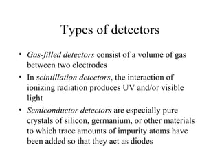
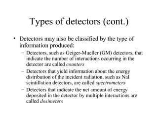
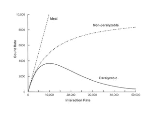
Radiation Detection &
   Measurement I
    Types of detectors
Types of detectors
• Gas-filled detectors consist of a volume of gas
  between two electrodes
• In scintillation detectors, the interaction of
  ionizing radiation produces UV and/or visible
  light
• Semiconductor detectors are especially pure
  crystals of silicon, germanium, or other materials
  to which trace amounts of impurity atoms have
  been added so that they act as diodes
Types of detectors (cont.)
• Detectors may also be classified by the type of
  information produced:
   – Detectors, such as Geiger-Mueller (GM) detectors, that
     indicate the number of interactions occurring in the
     detector are called counters
   – Detectors that yield information about the energy
     distribution of the incident radiation, such as NaI
     scintillation detectors, are called spectrometers
   – Detectors that indicate the net amount of energy
     deposited in the detector by multiple interactions are
     called dosimeters
Modes of operation
• In pulse mode, the signal from each
  interaction is processed individually
• In current mode, the electrical signals from
  individual interactions are averaged
  together, forming a net current signal
Interaction rate
• Main problem with detectors in pulse mode is that
  two interactions must be separated by a finite
  amount of time if they are to produce distinct
  signals
• This interval is called the dead time of the system
• If a second interaction occurs in this interval, its
  signal will be lost; if it occurs close enough to the
  first interaction, it may distort the signal from the
  first interaction
Dead time
• Dead time of a detector system largely determined
  by the component in the series with the longest
  dead time
   – Detector has longest dead time in GM counter systems
   – In multichannel analyzer systems the analog-to-digital
     converter often has the longest dead time
• GM counters have dead times ranging from tens to
  hundreds of microseconds, most other systems
  have dead times of less than a few microseconds
Paralyzable or nonparalyzable
• In a paralyzable system, an interaction that
  occurs during the dead time after a previous
  interaction extends the dead time
• In a nonparalyzable system, it does not
• At very high interaction rates, a paralyzable
  system will be unable to detect any
  interactions after the first, causing the
  detector to indicate a count rate of zero
Current mode operation
• In current mode, all information regarding
  individual interactions is lost
• If the amount of electrical charge collected from
  each interaction is proportional to the energy
  deposited by that interaction, then the net current
  is proportional to the dose rate in the detector
  material
• Used for detectors subjected to very high
  interaction rates
Spectroscopy
• Most spectrometers operated in pulse mode
• Amplitude of each pulse is proportional to the
  energy deposited in the detector by the interaction
  causing that pulse
• The energy deposited by an interaction is not
  always the total energy of the incident particle or
  photon
• A pulse height spectrum is usually depicted as a
  graph of the number of interactions depositing a
  particular amount of energy in the spectrometer as
  a function of energy
Detection efficiency
• The efficiency (sensitivity) of a detector is a
  measure of its ability to detect radiation
• Efficiency of a detection system operated in
  pulse mode is defined as the probability that
  a particle or photon emitted by a source will
  be detected
Number detected
Efficiency =
             Number emitted
             Number reaching detector
Efficiency =                            ×
                 Number emitted
                     Number detected
                Number reaching detector
Efficiency = Geometric efficiency × Intrinsic efficiency
Intrinsic efficiency
• Often called the quantum detection efficiency or
  QDE
• Determined by the energy of the photons and the
  atomic number, density, and thickness of the
  detector
• For a a parallel beam of monoenergetic photons
  incident on a detector of uniform thickness:
                                        − µx
         Intrinsic efficiency = 1 - e
Gas-filled detectors
• A gas-filled detector consists of a volume of gas
  between two electrodes, with an electrical
  potential difference (voltage) applied between the
  electrodes
• Ionizing radiation produces ion pairs in the gas
• Positive ions (cations) attracted to negative
  electrode (cathode); electrons or anions attracted
  to positive electrode (anode)
• In most detectors, cathode is the wall of the
  container that holds the gas and anode is a wire
  inside the container
Types of gas-filled detectors
• Three types of gas-filled detectors in common use:
   – Ionization chambers
   – Proportional counters
   – Geiger-Mueller (GM) counters
• Type determined primarily by the voltage applied
  between the two electrodes
• Ionization chambers have wider range of physical
  shape (parallel plates, concentric cylinders, etc.)
• Proportional counters and GM counters must have
  thin wire anode
Ionization chambers
• If gas is air and walls of chamber are of a material
  whose effective atomic number is similar to air,
  the amount of current produced is proportional to
  the exposure rate
• Air-filled ion chambers are used in portable
  survey meters, for performing QA testing of
  diagnostic and therapeutic x-ray machines, and are
  the detectors in most x-ray machine phototimers
• Low intrinsic efficiencies because of low densities
  of gases and low atomic numbers of most gases
Proportional counters
• Must contain a gas with specific properties
• Commonly used in standards laboratories,
  health physics laboratories, and for physics
  research
• Seldom used in medical centers
GM counters
• GM counters also must contain gases with specific
  properties
• Gas amplification produces billions of ion pairs
  after an interaction – signal from detector requires
  little amplification
• Often used for inexpensive survey meters
• In general, GM survey meters are inefficient
  detectors of x-rays and gamma rays
• Over-response to low energy x-rays – partially
  corrected by placing a thin layer of higher atomic
  number material around the detector
GM counters (cont.)
• GM detectors suffer from extremely long dead
  times – seldom used when accurate measurements
  are required of count rates greater than a few
  hundred counts per second
• Portable GM survey meter may become paralyzed
  in a very high radiation field – should always use
  ionization chamber instruments for measuring
  such fields
Scintillation detectors
• Scintillators are used in conventional film-screen
  radiography, many digital radiographic receptors,
  fluoroscopy, scintillation cameras, most CT
  scanners, and PET scanners
• Scintillation detectors consist of a scintillator and
  a device, such as a PMT, that converts the light
  into an electrical signal
Scintillators
• Desirable properties:
   – High conversion efficiency
   – Decay times of excited states should be short
   – Material transparent to its own emissions
   – Color of emitted light should match spectral sensitivity
     of the light receptor
   – For x-ray and gamma-ray detectors, µ should be large –
     high detection efficiencies
   – Rugged, unaffected by moisture, and inexpensive to
     manufacture
Scintillators (cont.)
• Amount of light emitted after an interaction
  increases with energy deposited by the
  interaction
• May be operated in pulse mode as
  spectrometers
• High conversion efficiency produces
  superior energy resolution
Materials
• Sodium iodide activated with thallium
  [NaI(Tl)], coupled to PMTs and operated in
  pulse mode, is used for most nuclear
  medicine applications
  – Fragile and hygroscopic
• Bismuth germanate (BGO) is coupled to
  PMTs and used in pulse mode as detectors
  in most PET scanners
Photomultiplier tubes
• PMTs perform two functions:
  – Conversion of ultraviolet and visible light
    photons into an electrical signal
  – Signal amplification, on the order of millions to
    billions
• Consists of an evacuated glass tube
  containing a photocathode, typically 10 to
  12 electrodes called dynodes, and an anode
Dynodes
• Electrons emitted by the photocathode are
  attracted to the first dynode and are accelerated to
  kinetic energies equal to the potential difference
  between the photocathode and the first dynode
• When these electrons strike the first dynode, about
  5 electrons are ejected from the dynode for each
  electron hitting it
• These electrons are attracted to the second dynode,
  and so on, finally reaching the anode
PMT amplification
• Total amplification of the PMT is the product of
  the individual amplifications at each dynode
• If a PMT has ten dynodes and the amplification at
  each stage is 5, the total amplification will be
  approximately 10,000,000
• Amplification can be adjusted by changing the
  voltage applied to the PMT

25 -radiation_detection_&_measurement_i

  • 1.
    Radiation Detection & Measurement I Types of detectors
  • 2.
    Types of detectors •Gas-filled detectors consist of a volume of gas between two electrodes • In scintillation detectors, the interaction of ionizing radiation produces UV and/or visible light • Semiconductor detectors are especially pure crystals of silicon, germanium, or other materials to which trace amounts of impurity atoms have been added so that they act as diodes
  • 3.
    Types of detectors(cont.) • Detectors may also be classified by the type of information produced: – Detectors, such as Geiger-Mueller (GM) detectors, that indicate the number of interactions occurring in the detector are called counters – Detectors that yield information about the energy distribution of the incident radiation, such as NaI scintillation detectors, are called spectrometers – Detectors that indicate the net amount of energy deposited in the detector by multiple interactions are called dosimeters
  • 4.
    Modes of operation •In pulse mode, the signal from each interaction is processed individually • In current mode, the electrical signals from individual interactions are averaged together, forming a net current signal
  • 5.
    Interaction rate • Mainproblem with detectors in pulse mode is that two interactions must be separated by a finite amount of time if they are to produce distinct signals • This interval is called the dead time of the system • If a second interaction occurs in this interval, its signal will be lost; if it occurs close enough to the first interaction, it may distort the signal from the first interaction
  • 6.
    Dead time • Deadtime of a detector system largely determined by the component in the series with the longest dead time – Detector has longest dead time in GM counter systems – In multichannel analyzer systems the analog-to-digital converter often has the longest dead time • GM counters have dead times ranging from tens to hundreds of microseconds, most other systems have dead times of less than a few microseconds
  • 7.
    Paralyzable or nonparalyzable •In a paralyzable system, an interaction that occurs during the dead time after a previous interaction extends the dead time • In a nonparalyzable system, it does not • At very high interaction rates, a paralyzable system will be unable to detect any interactions after the first, causing the detector to indicate a count rate of zero
  • 9.
    Current mode operation •In current mode, all information regarding individual interactions is lost • If the amount of electrical charge collected from each interaction is proportional to the energy deposited by that interaction, then the net current is proportional to the dose rate in the detector material • Used for detectors subjected to very high interaction rates
  • 10.
    Spectroscopy • Most spectrometersoperated in pulse mode • Amplitude of each pulse is proportional to the energy deposited in the detector by the interaction causing that pulse • The energy deposited by an interaction is not always the total energy of the incident particle or photon • A pulse height spectrum is usually depicted as a graph of the number of interactions depositing a particular amount of energy in the spectrometer as a function of energy
  • 12.
    Detection efficiency • Theefficiency (sensitivity) of a detector is a measure of its ability to detect radiation • Efficiency of a detection system operated in pulse mode is defined as the probability that a particle or photon emitted by a source will be detected
  • 13.
    Number detected Efficiency = Number emitted Number reaching detector Efficiency = × Number emitted Number detected Number reaching detector Efficiency = Geometric efficiency × Intrinsic efficiency
  • 15.
    Intrinsic efficiency • Oftencalled the quantum detection efficiency or QDE • Determined by the energy of the photons and the atomic number, density, and thickness of the detector • For a a parallel beam of monoenergetic photons incident on a detector of uniform thickness: − µx Intrinsic efficiency = 1 - e
  • 16.
    Gas-filled detectors • Agas-filled detector consists of a volume of gas between two electrodes, with an electrical potential difference (voltage) applied between the electrodes • Ionizing radiation produces ion pairs in the gas • Positive ions (cations) attracted to negative electrode (cathode); electrons or anions attracted to positive electrode (anode) • In most detectors, cathode is the wall of the container that holds the gas and anode is a wire inside the container
  • 18.
    Types of gas-filleddetectors • Three types of gas-filled detectors in common use: – Ionization chambers – Proportional counters – Geiger-Mueller (GM) counters • Type determined primarily by the voltage applied between the two electrodes • Ionization chambers have wider range of physical shape (parallel plates, concentric cylinders, etc.) • Proportional counters and GM counters must have thin wire anode
  • 20.
    Ionization chambers • Ifgas is air and walls of chamber are of a material whose effective atomic number is similar to air, the amount of current produced is proportional to the exposure rate • Air-filled ion chambers are used in portable survey meters, for performing QA testing of diagnostic and therapeutic x-ray machines, and are the detectors in most x-ray machine phototimers • Low intrinsic efficiencies because of low densities of gases and low atomic numbers of most gases
  • 22.
    Proportional counters • Mustcontain a gas with specific properties • Commonly used in standards laboratories, health physics laboratories, and for physics research • Seldom used in medical centers
  • 23.
    GM counters • GMcounters also must contain gases with specific properties • Gas amplification produces billions of ion pairs after an interaction – signal from detector requires little amplification • Often used for inexpensive survey meters • In general, GM survey meters are inefficient detectors of x-rays and gamma rays • Over-response to low energy x-rays – partially corrected by placing a thin layer of higher atomic number material around the detector
  • 26.
    GM counters (cont.) •GM detectors suffer from extremely long dead times – seldom used when accurate measurements are required of count rates greater than a few hundred counts per second • Portable GM survey meter may become paralyzed in a very high radiation field – should always use ionization chamber instruments for measuring such fields
  • 27.
    Scintillation detectors • Scintillatorsare used in conventional film-screen radiography, many digital radiographic receptors, fluoroscopy, scintillation cameras, most CT scanners, and PET scanners • Scintillation detectors consist of a scintillator and a device, such as a PMT, that converts the light into an electrical signal
  • 28.
    Scintillators • Desirable properties: – High conversion efficiency – Decay times of excited states should be short – Material transparent to its own emissions – Color of emitted light should match spectral sensitivity of the light receptor – For x-ray and gamma-ray detectors, µ should be large – high detection efficiencies – Rugged, unaffected by moisture, and inexpensive to manufacture
  • 29.
    Scintillators (cont.) • Amountof light emitted after an interaction increases with energy deposited by the interaction • May be operated in pulse mode as spectrometers • High conversion efficiency produces superior energy resolution
  • 30.
    Materials • Sodium iodideactivated with thallium [NaI(Tl)], coupled to PMTs and operated in pulse mode, is used for most nuclear medicine applications – Fragile and hygroscopic • Bismuth germanate (BGO) is coupled to PMTs and used in pulse mode as detectors in most PET scanners
  • 31.
    Photomultiplier tubes • PMTsperform two functions: – Conversion of ultraviolet and visible light photons into an electrical signal – Signal amplification, on the order of millions to billions • Consists of an evacuated glass tube containing a photocathode, typically 10 to 12 electrodes called dynodes, and an anode
  • 34.
    Dynodes • Electrons emittedby the photocathode are attracted to the first dynode and are accelerated to kinetic energies equal to the potential difference between the photocathode and the first dynode • When these electrons strike the first dynode, about 5 electrons are ejected from the dynode for each electron hitting it • These electrons are attracted to the second dynode, and so on, finally reaching the anode
  • 35.
    PMT amplification • Totalamplification of the PMT is the product of the individual amplifications at each dynode • If a PMT has ten dynodes and the amplification at each stage is 5, the total amplification will be approximately 10,000,000 • Amplification can be adjusted by changing the voltage applied to the PMT