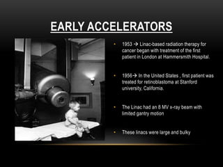
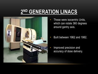
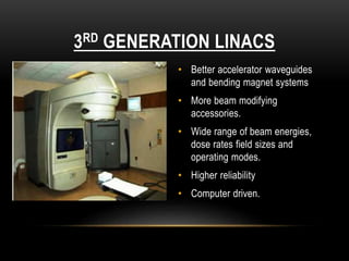
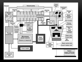
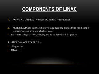
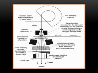
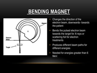
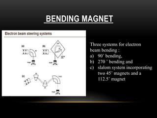
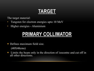
By DR. MARIYA KIKALI
DNB RESIDENT, RADIATION ONCOLOGY
WORKFLOW OF LINEAR ACCELERATOR
FLOW OF PRESENTATION
1. Introduction
2. Different generations of LINAC
3. Components of LINAC-
a) Magneteron
b) Klystron
c) Electron gun
d) Accelerating waveguide
e) Treatment head
f) Auxillary system
LINEAR ACCELERATOR
• It is a device that uses high-frequency electromagnetic waves to
accelerate charged particles such as electrons to high energies
through a linear tube.
• The high-energy electron beam itself can be used for treating
superficial tumors.
• Or it can be made to strike a target to produce X-rays for
treating deep-seated tumors.
EARLY ACCELERATORS
• 1953  Linac-based radiation therapy for
cancer began with treatment of the first
patient in London at Hammersmith Hospital.
• 1956 In the United States , first patient was
treated for retinoblastoma at Stanford
university, California.
• The Linac had an 8 MV x-ray beam with
limited gantry motion
• These linacs were large and bulky
2ND GENERATION LINACS
• These were isocentric Units,
which can rotate 360 degrees
around gantry axis.
• Built between 1962 and 1982.
• Improved precision and
accuracy of dose delivery.
3RD GENERATION LINACS
• Better accelerator waveguides
and bending magnet systems
• More beam modifying
accessories.
• Wide range of beam energies,
dose rates field sizes and
operating modes.
• Higher reliability
• Computer driven.
COMPONENTS OF LINAC
1. POWER SUPPLY: Provides DC supply to modulator.
2. MODULATOR: Supplies high voltage negative pulses from main supply
to microwave source and electron gun.
• Dose rate is regulated by varying the pulse repetition frequency.
3. MICROWAVE SOURCE :
• Magnetron
• Klystron
COMPONENTS OF LINAC
MAGNETRON
• It produces microwaves.
• It functions as a high-power oscillator, generating microwave
pulses
• The frequency of the microwaves within each pulse is about
3,000 MHz
• Magnetrons operate at a 2-MW peak power output to power low-
energy linacs (6 MV or less)
MAGNETRON- STRUCTURE
MAGNETRON- FUNCTION
Central cathode is heated by an inner filament
The electron are generated by thermionic emission
Static magnetic field is applied perpendicular to the plane of the
cross section of the cavities + a pulsed DC electric field is
applied between the cathode and the anode
Electrons emitted from the cathode are accelerated toward the
anode
Under the simultaneous influence of the magnetic field, the
electrons move in complex spirals toward the resonant cavities
Radiating energy in the
form of microwaves
KLYSTRON
• It is a microwave amplifier
(not a microwave producer)
• It is driven by a low-power
microwave oscillator
• Higher-energy linacs use
klystrons
KLYSTRON- STRUCTURE &
FUNCTION
 Velocity modulation: Velocity of electron is altered by the action of electric
field in the buncher cavity produced by low power microwave
 Electrons on arriving in the catcher cavity suffer deceleration due to
retarding electric field, thus kinetic energy(KE) of electrons is converted
into high-power microwaves
ELECTRON GUN
Electrons are
thermionically emitted
from the heated cathode
Accelerated towards the
perforated anode
Enter the accelerating
waveguide
ACCELERATING WAVEGUIDE
• Uses electromagnetic RF wave to
accelerate electrons to very high
velocities onto target or electron
window
• Types-
1. Travelling waveguide- The
traveling wave structures require a
terminating, or “dummy,” load to
absorb the residual power at the
end of the structure, thus
preventing a backward reflected
wave
2. Standing waveguide- Provide
maximum reflection of the waves at
both ends of the structure so that
the combination of forward and
reverse traveling waves will give
rise to stationary waves
Cutaway view of a standing wave accelerating
waveguide for a 6 MV linac
TREATMENT HEAD
 Contains components designed to
shape and monitor the treatment
beams.
 They include:
• Bending magnet
• Target
• Primary collimator
• Beam flattening filter/ scattering
foil
• Ion chambers
• Secondary collimators and
• One or more slots for trays,
wedges, blocks and compensators
BENDING MAGNET
• Changes the direction of the
electron beam, downwards- towards
the patient
• Bends the pulsed electron beam
towards the target for X-rays or
scattering foil for electron
treatments
• Produces different beam paths for
different energies
• Needed for energies greater than 6
MeV.
BENDING MAGNET
Three systems for electron
beam bending :
a) 90˚ bending,
b) 270 ˚ bending and
c) slalom system incorporating
two 45˚ magnets and a
112.5˚ magnet
TARGET
The target material:
• Tungsten for electron energies upto 10 MeV
• Higher energies - Aluminium
PRIMARY COLLIMATOR
 Defines maximum field size.
(40X40cms)
 Limits the beam only in the direction of isocentre and cut off in
all other directions.
FLATTENING FILTER
 Photon dose distribution produced
by a linac is strongly forward
peaked
 Flattening filter is inserted in the
path of beam to make the beam
uniform across the field.
 Material: Lead, tungsten, uranium
steel, aluminium or a combination.
MONITORING SYSTEM- ION CHAMBER
 The function of the ion chamber is to monitor dose rate,
integrated dose, and field symmetry.
 The monitor chambers in the treatment head are usually sealed
so that their response is not influenced by temperature and
pressure of the outside air.
SECONDARY COLLIMATOR
 Consist of four blocks, two forming the upper and two forming
the lower jaws of the collimator
 It helps to generate the field shape of any size according to
treatment planning – square or rectangular
 High density material like lead or tungsten alloy
 Thick enough to absorb 98% of the main beam
 3 types of secondary collimators :
1. Symmetric
2. Independent
3. Multileaf
MULTI LEAF COLLIMATOR(MLC)
• MLC consists of a large number of collimating blocks or leafs
that can be driven automatically, independent of each other, to
generate a field of any shape.
• The thickness of leaves along the beam direction is sufficient to
provide acceptably low beam transmission (less than 2%).
• Typical MLC systems consist of 60 to 80 pairs
• The individual leaf has a width of 1 cm or less as projected at the
isocenter
• The leaves are made of tungsten alloy
MULTI LEAF COLLIMATORS OF
DIFFERENT LINACS
VARIAN SEIMENS
ELEKTA
ELECTRON BEAM MODE
SCATTERING FOIL
• It is mounted on a rotating carousel or sliding drawer for ease of
mechanical positioning into the beam, as required
• In the electron mode of linac operation, electron beam, instead
of striking the target, is made to strike an electron scattering foil
• Use- 1. To spread the beam
2. To get a uniform electron fluence across the treatment
field.
• Consists of a thin high-Z metallic foil (e.g., lead, tantalum)
AUXILIARY SYSTEM
1. Vacuum pumping system- for accelerating guide and the RF
generator;
2. Water cooling system- used for cooling the accelerating guide,
target, circulator and RF generator;
3. An optional air pressure system- for pneumatic movement of the
target and other beam shaping components;
4. Shielding against leakage radiation.
TREATMENT COUCH
• The treatment couch or table is where patient lays still to receive the
radiation treatment
• It moves up/down, right/left and in/out
• Robotic couches are being used in some linacs for 3 more degree of
freedom
• Made with carbon fibre top
THANK YOU

LINAC- LINEAR ACCELERATOR

  • 1.
    By DR. MARIYAKIKALI DNB RESIDENT, RADIATION ONCOLOGY WORKFLOW OF LINEAR ACCELERATOR
  • 2.
    FLOW OF PRESENTATION 1.Introduction 2. Different generations of LINAC 3. Components of LINAC- a) Magneteron b) Klystron c) Electron gun d) Accelerating waveguide e) Treatment head f) Auxillary system
  • 3.
    LINEAR ACCELERATOR • Itis a device that uses high-frequency electromagnetic waves to accelerate charged particles such as electrons to high energies through a linear tube. • The high-energy electron beam itself can be used for treating superficial tumors. • Or it can be made to strike a target to produce X-rays for treating deep-seated tumors.
  • 4.
    EARLY ACCELERATORS • 1953 Linac-based radiation therapy for cancer began with treatment of the first patient in London at Hammersmith Hospital. • 1956 In the United States , first patient was treated for retinoblastoma at Stanford university, California. • The Linac had an 8 MV x-ray beam with limited gantry motion • These linacs were large and bulky
  • 5.
    2ND GENERATION LINACS •These were isocentric Units, which can rotate 360 degrees around gantry axis. • Built between 1962 and 1982. • Improved precision and accuracy of dose delivery.
  • 6.
    3RD GENERATION LINACS •Better accelerator waveguides and bending magnet systems • More beam modifying accessories. • Wide range of beam energies, dose rates field sizes and operating modes. • Higher reliability • Computer driven.
  • 7.
  • 9.
    1. POWER SUPPLY:Provides DC supply to modulator. 2. MODULATOR: Supplies high voltage negative pulses from main supply to microwave source and electron gun. • Dose rate is regulated by varying the pulse repetition frequency. 3. MICROWAVE SOURCE : • Magnetron • Klystron COMPONENTS OF LINAC
  • 10.
    MAGNETRON • It producesmicrowaves. • It functions as a high-power oscillator, generating microwave pulses • The frequency of the microwaves within each pulse is about 3,000 MHz • Magnetrons operate at a 2-MW peak power output to power low- energy linacs (6 MV or less)
  • 11.
  • 12.
    MAGNETRON- FUNCTION Central cathodeis heated by an inner filament The electron are generated by thermionic emission Static magnetic field is applied perpendicular to the plane of the cross section of the cavities + a pulsed DC electric field is applied between the cathode and the anode Electrons emitted from the cathode are accelerated toward the anode Under the simultaneous influence of the magnetic field, the electrons move in complex spirals toward the resonant cavities Radiating energy in the form of microwaves
  • 13.
    KLYSTRON • It isa microwave amplifier (not a microwave producer) • It is driven by a low-power microwave oscillator • Higher-energy linacs use klystrons
  • 14.
    KLYSTRON- STRUCTURE & FUNCTION Velocity modulation: Velocity of electron is altered by the action of electric field in the buncher cavity produced by low power microwave  Electrons on arriving in the catcher cavity suffer deceleration due to retarding electric field, thus kinetic energy(KE) of electrons is converted into high-power microwaves
  • 15.
    ELECTRON GUN Electrons are thermionicallyemitted from the heated cathode Accelerated towards the perforated anode Enter the accelerating waveguide
  • 16.
    ACCELERATING WAVEGUIDE • Useselectromagnetic RF wave to accelerate electrons to very high velocities onto target or electron window • Types- 1. Travelling waveguide- The traveling wave structures require a terminating, or “dummy,” load to absorb the residual power at the end of the structure, thus preventing a backward reflected wave 2. Standing waveguide- Provide maximum reflection of the waves at both ends of the structure so that the combination of forward and reverse traveling waves will give rise to stationary waves Cutaway view of a standing wave accelerating waveguide for a 6 MV linac
  • 17.
    TREATMENT HEAD  Containscomponents designed to shape and monitor the treatment beams.  They include: • Bending magnet • Target • Primary collimator • Beam flattening filter/ scattering foil • Ion chambers • Secondary collimators and • One or more slots for trays, wedges, blocks and compensators
  • 19.
    BENDING MAGNET • Changesthe direction of the electron beam, downwards- towards the patient • Bends the pulsed electron beam towards the target for X-rays or scattering foil for electron treatments • Produces different beam paths for different energies • Needed for energies greater than 6 MeV.
  • 20.
    BENDING MAGNET Three systemsfor electron beam bending : a) 90˚ bending, b) 270 ˚ bending and c) slalom system incorporating two 45˚ magnets and a 112.5˚ magnet
  • 21.
    TARGET The target material: •Tungsten for electron energies upto 10 MeV • Higher energies - Aluminium PRIMARY COLLIMATOR  Defines maximum field size. (40X40cms)  Limits the beam only in the direction of isocentre and cut off in all other directions.
  • 22.
    FLATTENING FILTER  Photondose distribution produced by a linac is strongly forward peaked  Flattening filter is inserted in the path of beam to make the beam uniform across the field.  Material: Lead, tungsten, uranium steel, aluminium or a combination.
  • 23.
    MONITORING SYSTEM- IONCHAMBER  The function of the ion chamber is to monitor dose rate, integrated dose, and field symmetry.  The monitor chambers in the treatment head are usually sealed so that their response is not influenced by temperature and pressure of the outside air.
  • 24.
    SECONDARY COLLIMATOR  Consistof four blocks, two forming the upper and two forming the lower jaws of the collimator  It helps to generate the field shape of any size according to treatment planning – square or rectangular  High density material like lead or tungsten alloy  Thick enough to absorb 98% of the main beam  3 types of secondary collimators : 1. Symmetric 2. Independent 3. Multileaf
  • 25.
    MULTI LEAF COLLIMATOR(MLC) •MLC consists of a large number of collimating blocks or leafs that can be driven automatically, independent of each other, to generate a field of any shape. • The thickness of leaves along the beam direction is sufficient to provide acceptably low beam transmission (less than 2%). • Typical MLC systems consist of 60 to 80 pairs • The individual leaf has a width of 1 cm or less as projected at the isocenter • The leaves are made of tungsten alloy
  • 26.
    MULTI LEAF COLLIMATORSOF DIFFERENT LINACS VARIAN SEIMENS ELEKTA
  • 27.
  • 28.
    SCATTERING FOIL • Itis mounted on a rotating carousel or sliding drawer for ease of mechanical positioning into the beam, as required • In the electron mode of linac operation, electron beam, instead of striking the target, is made to strike an electron scattering foil • Use- 1. To spread the beam 2. To get a uniform electron fluence across the treatment field. • Consists of a thin high-Z metallic foil (e.g., lead, tantalum)
  • 29.
    AUXILIARY SYSTEM 1. Vacuumpumping system- for accelerating guide and the RF generator; 2. Water cooling system- used for cooling the accelerating guide, target, circulator and RF generator; 3. An optional air pressure system- for pneumatic movement of the target and other beam shaping components; 4. Shielding against leakage radiation.
  • 30.
    TREATMENT COUCH • Thetreatment couch or table is where patient lays still to receive the radiation treatment • It moves up/down, right/left and in/out • Robotic couches are being used in some linacs for 3 more degree of freedom • Made with carbon fibre top
  • 31.