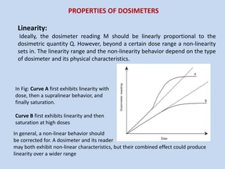
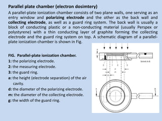
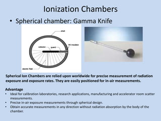
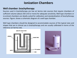
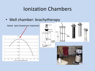
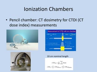
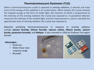
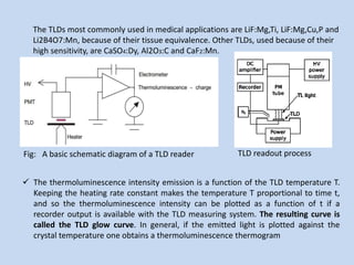
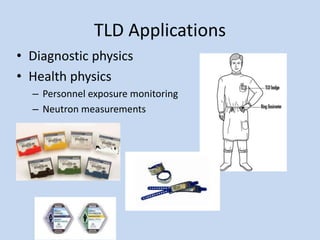
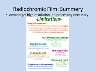
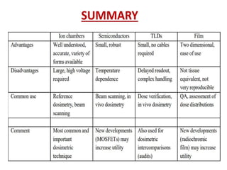
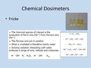
This document discusses different types of radiation dosimeters, including their properties, uses, and limitations. It focuses on ionization chamber dosimetry systems, describing cylindrical thimble chambers, parallel plate chambers, spherical chambers, well chambers, and pencil chambers. It also discusses thermoluminescent dosimeters (TLD), noting that TLD crystals absorb and trap radiation energy then emit light when heated, allowing dose measurement. The document provides an overview of key factors such as linearity, dose rate dependence, energy dependence, and directional dependence for dosimeters.
TISSUE PHANTOM RATIO - THE PHOTON BEAM QUALITY INDEXVictor Ekpo
TPR(20,10) is the recommended photon beam quality index by IAEA TRS-398 for megavoltage clinical photons generated by linear accelerators. This presentation goes through the basics of Tissue Phantom Ratio (TPR).
Cavity theory.. Radiotherapy..
I explained about Bragg-gray, Spencer attix and Burlin theory..
In future I'll try to explain this with some more points. So wait for the updation.
I referred Radiation oncology (IAEA) book and
Introduction to Radiological Physics and Radiation Dosimetry by Frank Herbert Attix book
In 2000 IAEA published another International Code of Practice.
“Absorbed Dose Determination in External Beam Radiotherapy” (Technical Report Series No. 398)
Recommending procedures to obtain the absorbed dose in water from measurements made with an ionisation chamber in external beam radiotherapy (EBRT).
CONTENTS
Electron arc therapy.
Introduction to electron arc therapy
Calibration of electron arc therapy
field shaping
beam energy
Treatment planning
location of the isocentre
scanning field width
collimation used in electron arc therapy.
summary
The file contains the Resistance of Electricity and how it affects greatly on the technology that we are using nowadays. Together with some calculation and trivia, I hope will enjoy watching and learning the presentation
Pharmaceutical Inorganic chemistry UNIT-V Radiopharmaceutical.pptx
Isotopes Types of decay
Alpha rays, which could barely penetrate a piece of paper
Beta rays, which could penetrate 3 mm of aluminium
Gamma rays, which could penetrate several centimetres of lead
Units of Radioactivity:
Measurement of Radioactivity
The measurement of nuclear radiation and detection is an important aspect in the identification of type of radiations (, , ) and to assay the radionuclide emitting the radiation, suitable detectors are required. The radiations are identified on the basis of their properties.
e.g. Ionization effect is measured in Ionization Chamber, Proportional Counter and Geiger Muller Counter.
The scintillation effect of radiation is measured using scintillation detector and the photographic effect is measured by Autoradiography.
Gas Filled Detectors:
Ionization Chamber:
Proportional Counters:
Geiger-Muller Counter
Properties of α, β, γ radiations
Half –life of Radioelement
Sodium Iodide (I131)
Handling and Storage of Radioactive Material:
Storage of Radioactive Substances –
Precautions For Handling Radioactive Substances
Labelling of Radioactive Substances
Pharmaceutical Application Of Radioactive Substances
Knee anatomy and clinical tests 2024.pdfvimalpl1234
This includes all relevant anatomy and clinical tests compiled from standard textbooks, Campbell,netter etc..It is comprehensive and best suited for orthopaedicians and orthopaedic residents.
micro teaching on communication m.sc nursing.pdfAnurag Sharma
Microteaching is a unique model of practice teaching. It is a viable instrument for the. desired change in the teaching behavior or the behavior potential which, in specified types of real. classroom situations, tends to facilitate the achievement of specified types of objectives.
Lung Cancer: Artificial Intelligence, Synergetics, Complex System Analysis, S...Oleg Kshivets
RESULTS: Overall life span (LS) was 2252.1±1742.5 days and cumulative 5-year survival (5YS) reached 73.2%, 10 years – 64.8%, 20 years – 42.5%. 513 LCP lived more than 5 years (LS=3124.6±1525.6 days), 148 LCP – more than 10 years (LS=5054.4±1504.1 days).199 LCP died because of LC (LS=562.7±374.5 days). 5YS of LCP after bi/lobectomies was significantly superior in comparison with LCP after pneumonectomies (78.1% vs.63.7%, P=0.00001 by log-rank test). AT significantly improved 5YS (66.3% vs. 34.8%) (P=0.00000 by log-rank test) only for LCP with N1-2. Cox modeling displayed that 5YS of LCP significantly depended on: phase transition (PT) early-invasive LC in terms of synergetics, PT N0—N12, cell ratio factors (ratio between cancer cells- CC and blood cells subpopulations), G1-3, histology, glucose, AT, blood cell circuit, prothrombin index, heparin tolerance, recalcification time (P=0.000-0.038). Neural networks, genetic algorithm selection and bootstrap simulation revealed relationships between 5YS and PT early-invasive LC (rank=1), PT N0—N12 (rank=2), thrombocytes/CC (3), erythrocytes/CC (4), eosinophils/CC (5), healthy cells/CC (6), lymphocytes/CC (7), segmented neutrophils/CC (8), stick neutrophils/CC (9), monocytes/CC (10); leucocytes/CC (11). Correct prediction of 5YS was 100% by neural networks computing (area under ROC curve=1.0; error=0.0).
CONCLUSIONS: 5YS of LCP after radical procedures significantly depended on: 1) PT early-invasive cancer; 2) PT N0--N12; 3) cell ratio factors; 4) blood cell circuit; 5) biochemical factors; 6) hemostasis system; 7) AT; 8) LC characteristics; 9) LC cell dynamics; 10) surgery type: lobectomy/pneumonectomy; 11) anthropometric data. Optimal diagnosis and treatment strategies for LC are: 1) screening and early detection of LC; 2) availability of experienced thoracic surgeons because of complexity of radical procedures; 3) aggressive en block surgery and adequate lymph node dissection for completeness; 4) precise prediction; 5) adjuvant chemoimmunoradiotherapy for LCP with unfavorable prognosis.
Title: Sense of Taste
Presenter: Dr. Faiza, Assistant Professor of Physiology
Qualifications:
MBBS (Best Graduate, AIMC Lahore)
FCPS Physiology
ICMT, CHPE, DHPE (STMU)
MPH (GC University, Faisalabad)
MBA (Virtual University of Pakistan)
Learning Objectives:
Describe the structure and function of taste buds.
Describe the relationship between the taste threshold and taste index of common substances.
Explain the chemical basis and signal transduction of taste perception for each type of primary taste sensation.
Recognize different abnormalities of taste perception and their causes.
Key Topics:
Significance of Taste Sensation:
Differentiation between pleasant and harmful food
Influence on behavior
Selection of food based on metabolic needs
Receptors of Taste:
Taste buds on the tongue
Influence of sense of smell, texture of food, and pain stimulation (e.g., by pepper)
Primary and Secondary Taste Sensations:
Primary taste sensations: Sweet, Sour, Salty, Bitter, Umami
Chemical basis and signal transduction mechanisms for each taste
Taste Threshold and Index:
Taste threshold values for Sweet (sucrose), Salty (NaCl), Sour (HCl), and Bitter (Quinine)
Taste index relationship: Inversely proportional to taste threshold
Taste Blindness:
Inability to taste certain substances, particularly thiourea compounds
Example: Phenylthiocarbamide
Structure and Function of Taste Buds:
Composition: Epithelial cells, Sustentacular/Supporting cells, Taste cells, Basal cells
Features: Taste pores, Taste hairs/microvilli, and Taste nerve fibers
Location of Taste Buds:
Found in papillae of the tongue (Fungiform, Circumvallate, Foliate)
Also present on the palate, tonsillar pillars, epiglottis, and proximal esophagus
Mechanism of Taste Stimulation:
Interaction of taste substances with receptors on microvilli
Signal transduction pathways for Umami, Sweet, Bitter, Sour, and Salty tastes
Taste Sensitivity and Adaptation:
Decrease in sensitivity with age
Rapid adaptation of taste sensation
Role of Saliva in Taste:
Dissolution of tastants to reach receptors
Washing away the stimulus
Taste Preferences and Aversions:
Mechanisms behind taste preference and aversion
Influence of receptors and neural pathways
Impact of Sensory Nerve Damage:
Degeneration of taste buds if the sensory nerve fiber is cut
Abnormalities of Taste Detection:
Conditions: Ageusia, Hypogeusia, Dysgeusia (parageusia)
Causes: Nerve damage, neurological disorders, infections, poor oral hygiene, adverse drug effects, deficiencies, aging, tobacco use, altered neurotransmitter levels
Neurotransmitters and Taste Threshold:
Effects of serotonin (5-HT) and norepinephrine (NE) on taste sensitivity
Supertasters:
25% of the population with heightened sensitivity to taste, especially bitterness
Increased number of fungiform papillae
These simplified slides by Dr. Sidra Arshad present an overview of the non-respiratory functions of the respiratory tract.
Learning objectives:
1. Enlist the non-respiratory functions of the respiratory tract
2. Briefly explain how these functions are carried out
3. Discuss the significance of dead space
4. Differentiate between minute ventilation and alveolar ventilation
5. Describe the cough and sneeze reflexes
Study Resources:
1. Chapter 39, Guyton and Hall Textbook of Medical Physiology, 14th edition
2. Chapter 34, Ganong’s Review of Medical Physiology, 26th edition
3. Chapter 17, Human Physiology by Lauralee Sherwood, 9th edition
4. Non-respiratory functions of the lungs https://academic.oup.com/bjaed/article/13/3/98/278874
Title: Sense of Smell
Presenter: Dr. Faiza, Assistant Professor of Physiology
Qualifications:
MBBS (Best Graduate, AIMC Lahore)
FCPS Physiology
ICMT, CHPE, DHPE (STMU)
MPH (GC University, Faisalabad)
MBA (Virtual University of Pakistan)
Learning Objectives:
Describe the primary categories of smells and the concept of odor blindness.
Explain the structure and location of the olfactory membrane and mucosa, including the types and roles of cells involved in olfaction.
Describe the pathway and mechanisms of olfactory signal transmission from the olfactory receptors to the brain.
Illustrate the biochemical cascade triggered by odorant binding to olfactory receptors, including the role of G-proteins and second messengers in generating an action potential.
Identify different types of olfactory disorders such as anosmia, hyposmia, hyperosmia, and dysosmia, including their potential causes.
Key Topics:
Olfactory Genes:
3% of the human genome accounts for olfactory genes.
400 genes for odorant receptors.
Olfactory Membrane:
Located in the superior part of the nasal cavity.
Medially: Folds downward along the superior septum.
Laterally: Folds over the superior turbinate and upper surface of the middle turbinate.
Total surface area: 5-10 square centimeters.
Olfactory Mucosa:
Olfactory Cells: Bipolar nerve cells derived from the CNS (100 million), with 4-25 olfactory cilia per cell.
Sustentacular Cells: Produce mucus and maintain ionic and molecular environment.
Basal Cells: Replace worn-out olfactory cells with an average lifespan of 1-2 months.
Bowman’s Gland: Secretes mucus.
Stimulation of Olfactory Cells:
Odorant dissolves in mucus and attaches to receptors on olfactory cilia.
Involves a cascade effect through G-proteins and second messengers, leading to depolarization and action potential generation in the olfactory nerve.
Quality of a Good Odorant:
Small (3-20 Carbon atoms), volatile, water-soluble, and lipid-soluble.
Facilitated by odorant-binding proteins in mucus.
Membrane Potential and Action Potential:
Resting membrane potential: -55mV.
Action potential frequency in the olfactory nerve increases with odorant strength.
Adaptation Towards the Sense of Smell:
Rapid adaptation within the first second, with further slow adaptation.
Psychological adaptation greater than receptor adaptation, involving feedback inhibition from the central nervous system.
Primary Sensations of Smell:
Camphoraceous, Musky, Floral, Pepperminty, Ethereal, Pungent, Putrid.
Odor Detection Threshold:
Examples: Hydrogen sulfide (0.0005 ppm), Methyl-mercaptan (0.002 ppm).
Some toxic substances are odorless at lethal concentrations.
Characteristics of Smell:
Odor blindness for single substances due to lack of appropriate receptor protein.
Behavioral and emotional influences of smell.
Transmission of Olfactory Signals:
From olfactory cells to glomeruli in the olfactory bulb, involving lateral inhibition.
Primitive, less old, and new olfactory systems with different path
TEST BANK for Operations Management, 14th Edition by William J. Stevenson, Ve...kevinkariuki227
TEST BANK for Operations Management, 14th Edition by William J. Stevenson, Verified Chapters 1 - 19, Complete Newest Version.pdf
Prix Galien International 2024 Forum ProgramLevi Shapiro
June 20, 2024, Prix Galien International and Jerusalem Ethics Forum in ROME. Detailed agenda including panels:
- ADVANCES IN CARDIOLOGY: A NEW PARADIGM IS COMING
- WOMEN’S HEALTH: FERTILITY PRESERVATION
- WHAT’S NEW IN THE TREATMENT OF INFECTIOUS,
ONCOLOGICAL AND INFLAMMATORY SKIN DISEASES?
- ARTIFICIAL INTELLIGENCE AND ETHICS
- GENE THERAPY
- BEYOND BORDERS: GLOBAL INITIATIVES FOR DEMOCRATIZING LIFE SCIENCE TECHNOLOGIES AND PROMOTING ACCESS TO HEALTHCARE
- ETHICAL CHALLENGES IN LIFE SCIENCES
- Prix Galien International Awards Ceremony
New Directions in Targeted Therapeutic Approaches for Older Adults With Mantl...i3 Health
i3 Health is pleased to make the speaker slides from this activity available for use as a non-accredited self-study or teaching resource.
This slide deck presented by Dr. Kami Maddocks, Professor-Clinical in the Division of Hematology and
Associate Division Director for Ambulatory Operations
The Ohio State University Comprehensive Cancer Center, will provide insight into new directions in targeted therapeutic approaches for older adults with mantle cell lymphoma.
STATEMENT OF NEED
Mantle cell lymphoma (MCL) is a rare, aggressive B-cell non-Hodgkin lymphoma (NHL) accounting for 5% to 7% of all lymphomas. Its prognosis ranges from indolent disease that does not require treatment for years to very aggressive disease, which is associated with poor survival (Silkenstedt et al, 2021). Typically, MCL is diagnosed at advanced stage and in older patients who cannot tolerate intensive therapy (NCCN, 2022). Although recent advances have slightly increased remission rates, recurrence and relapse remain very common, leading to a median overall survival between 3 and 6 years (LLS, 2021). Though there are several effective options, progress is still needed towards establishing an accepted frontline approach for MCL (Castellino et al, 2022). Treatment selection and management of MCL are complicated by the heterogeneity of prognosis, advanced age and comorbidities of patients, and lack of an established standard approach for treatment, making it vital that clinicians be familiar with the latest research and advances in this area. In this activity chaired by Michael Wang, MD, Professor in the Department of Lymphoma & Myeloma at MD Anderson Cancer Center, expert faculty will discuss prognostic factors informing treatment, the promising results of recent trials in new therapeutic approaches, and the implications of treatment resistance in therapeutic selection for MCL.
Target Audience
Hematology/oncology fellows, attending faculty, and other health care professionals involved in the treatment of patients with mantle cell lymphoma (MCL).
Learning Objectives
1.) Identify clinical and biological prognostic factors that can guide treatment decision making for older adults with MCL
2.) Evaluate emerging data on targeted therapeutic approaches for treatment-naive and relapsed/refractory MCL and their applicability to older adults
3.) Assess mechanisms of resistance to targeted therapies for MCL and their implications for treatment selection
1. Radiation Dosimetry
Md. Motiur Rahma, M. Sc
Chief Medical Physicist &
Assistant Project Director
TMSS Cancer Center
Bogura, Bangladesh
2. Learning Objectives
• Overview of different types of dosimeters
• Understand the radiation-induced process and
the meaning of measured signal
• Learn about the clinical applications and
advantages/issues with each type of
dosimeter
3. Linearity:
Ideally, the dosimeter reading M should be linearly proportional to the
dosimetric quantity Q. However, beyond a certain dose range a non-linearity
sets in. The linearity range and the non-linearity behavior depend on the type
of dosimeter and its physical characteristics.
In Fig: Curve A first exhibits linearity with
dose, then a supralinear behavior, and
finally saturation.
Curve B first exhibits linearity and then
saturation at high doses
In general, a non-linear behavior should
be corrected for. A dosimeter and its reader
may both exhibit non-linear characteristics, but their combined effect could produce
linearity over a wider range
PROPERTIES OF DOSIMETERS
4. Dose rate dependence:
Ideally, the response of a dosimetry system M/Q at two different dose rates
((dQ/dt)1 and (dQ/dt)2) should remain constant. In reality, the dose rate may
influence the dosimeter readings and appropriate corrections are necessary,
for example: recombination corrections for ionization chambers in pulsed
beams
Energy dependence:
The response of a dosimetry system M/Q is generally a function of radiation
beam quality (energy). Since the dosimetry systems are calibrated at a
specified radiation beam quality (or qualities) and used over a much wider
energy range, the variation of the response of a dosimetry system with
radiation quality (called energy dependence) requires correction.
5. Directional dependence:
The variation in response of a dosimeter with the angle of incidence of
radiation is known as the directional, or angular, dependence of the dosimeter.
Dosimeters usually exhibit directional dependence, due to their constructional
details, physical size and the energy of the incident radiation. Directional
dependence is important in certain applications,
for example in in vivo dosimetry while using semiconductor dosimeters.
Therapy dosimeters are generally used in the same geometry as that in which
they are calibrated.
6. Readout convenience:
Direct reading dosimeters (e.g. ionization chambers) are generally more
convenient than passive dosimeters (i.e. those that are read after due processing
following the exposure, for example TLDs and films). While some dosimeters are
inherently of the integrating type (e.g. TLDs and gels), others can measure in
both integral and differential modes (ionization chambers)
Convenience of use:
Ionization chambers are reusable, with no or little change in sensitivity within
their lifespan. Semiconductor dosimeters are reusable, but with a gradual loss
of sensitivity within their lifespan; however, some dosimeters are not reusable
(e.g. films, gels and alanine). Some dosimeters measure dose distribution in a
single exposure (e.g. films and gels) and some dosimeters are quite rugged (i.e.
handling will not influence sensitivity, for example ionization chambers), while
others are sensitive to handling (e.g. TLDs).
8. Chambers and electrometers
Ionization chambers are used in radiotherapy and in diagnostic radiology for the
determination of radiation dose. The dose determination in reference irradiation
conditions is also called beam calibration. Ionization chambers come in various shapes
and sizes, depending upon the specific requirements, but generally they all have the
following properties:
An ionization chamber is basically a gas filled cavity surrounded by a conductive outer
wall and having a central collecting electrode. The wall and the collecting electrode are
separated with a high quality insulator to reduce the leakage current when a polarizing
voltage is applied to the chamber.
A guard electrode is usually provided in the chamber to further reduce chamber
leakage. The guard electrode intercepts the leakage current and allows it to flow to
ground, bypassing the collecting electrode. It also ensures improved field uniformity in
the active or sensitive volume of the chamber, with resulting advantages in charge
collection.
9. Measurements with open air ionization chambers require temperature and
pressure correction to account for the change in the mass of air in the
chamber volume, which changes with the ambient temperature and
pressure
Electrometers are devices for measuring small currents, of the order of
𝟏𝟎−𝟗A or less. An electrometer used in conjunction with an ionization
chamber is a high gain, negative feedback, operational amplifier with a
standard resistor or a standard capacitor in the feedback path to measure
the chamber current or charge collected over a fixed time interval as
shown schematically in Fig
Fig: Electrometer in feedback mode of operation
10. Ionization Chambers
Cylindrical (thimble type) ionization chambers:
The most popular cylindrical ionization chamber is the 0.6 cm3 chamber
designed by Farmer and originally manufactured by Baldwin, but now
available from several vendors, for beam calibration in radiotherapy
dosimetry. Its chamber sensitive volume resembles a thimble, and hence the
Farmer type chamber is also known as a thimble chamber. A schematic
diagram of a Farmer type thimble ionization chamber is shown in Fig below
Farmer typed chamber
11. Cylindrical (thimble type) ionization chambers:
Cylindrical chambers are produced by various manufacturers, with active volumes
between 0.1 and 1 cm3 . They typically have an internal length not greater than 25 mm
and an internal diameter not greater than 7 mm. The wall material is of low atomic
number Z (i.e. tissue or air equivalent), with the thickness less than 0.1 g/cm2 . A
chamber is equipped with a buildup cap with a thickness of about 0.5 g/cm2 for
calibration free in air using Cobalt-60 radiation. The chamber construction should be as
homogeneous as possible, although an aluminum central electrode of about 1 mm in
diameter is typically
12. Parallel plate chamber (electron dosimtery)
A parallel-plate ionization chamber consists of two plane walls, one serving as an
entry window and polarizing electrode and the other as the back wall and
collecting electrode, as well as a guard ring system. The back wall is usually a
block of conducting plastic or a non-conducting material (usually Perspex or
polystyrene) with a thin conducting layer of graphite forming the collecting
electrode and the guard ring system on top. A schematic diagram of a parallel-
plate ionization chamber is shown in Fig.
FIG. Parallel-plate ionization chamber.
1: the polarizing electrode.
2: the measuring electrode.
3: the guard ring.
a: the height (electrode separation) of the air
cavity.
d: the diameter of the polarizing electrode.
m: the diameter of the collecting electrode.
g: the width of the guard ring.
13. Parallel plate chamber (electron dosimtery)
The parallel-plate chamber is recommended for dosimetry of electron beams
with energies below 10 MeV. It is also used for surface dose and depth dose
measurements in the buildup region of megavoltage photon beams.
14. Ionization Chambers
• Spherical chamber: Gamma Knife
Spherical Ion Chambers are relied upon worldwide for precise measurement of radiation
exposure and exposure rates. They are easily positioned for in-air measurements.
Advantage
• Ideal for calibration laboratories, research applications, manufacturing and accelerator room scatter
measurements.
• Precise in-air exposure measurements through spherical design.
• Obtain accurate measurements in any direction without radiation absorption by the body of the
chamber.
15. Ionization Chambers
Well chamber: brachytherapy
Sources used in brachytherapy are low air kerma rate sources that require chambers of
sufficient volume (about 250 cm3 or more) for adequate sensitivity. Well type chambers or
re-entrant chambers are ideally suited for calibration and standardization of brachytherapy
sources. Figure: shows a schematic diagram of a well type chamber.
Well type chambers should be designed to accommodate sources of the typical sizes and
shapes that are in clinical use in brachytherapy and are usually calibrated in terms of the
reference air kerma rate.
19. Ionization Chambers: Other Issues
• Stem effect: response from stem not thimble
• Depends on chamber design (guarding)
– Well guarded chamber: <0.1%
– Guarded chamber: 0.1-0.3%
– Unguarded chamber: 0.3-0.6%
• Function of energy and beam size
20. Ionization Chambers: Other Issues
• Leakage:
– Source: chamber, cable, electrometer
– Should measure leakage as a system before taking
measurements
– Leakage in the chamber is generally 1 to 10 femto-
amperes for a good chamber
22. When a thermoluminescent crystal is exposed to ionizing radiation, it absorbs and traps
some of the energy of the radiation in its crystal lattice. When heated, the crystal releases
the trapped energy in the form of visible light, the intensity of which is proportional to
the intensity of the ionizing radiation the crystal was exposed to. A specialized detector
measures the intensity of the emitted light, and this measurement is used to calculate the
approximate dose of ionizing radiation the crystal was exposed to.
Materials exhibiting thermoluminescence in response to ionizing radiation
include calcium fluoride, lithium fluoride, calcium sulfate, lithium borate, calcium
borate, potassium bromide, and feldspar. It was invented in 1954 by Professor Farrington
Daniels
Advantages :
• Small size
• Wider linear dose
response range
• Reusable
Thermoluminescent Dosimeter (TLD)
23. The TLDs most commonly used in medical applications are LiF:Mg,Ti, LiF:Mg,Cu,P and
Li2B4O7:Mn, because of their tissue equivalence. Other TLDs, used because of their
high sensitivity, are CaSO4:Dy, Al2O3:C and CaF2:Mn.
Fig: A basic schematic diagram of a TLD reader
The thermoluminescence intensity emission is a function of the TLD temperature T.
Keeping the heating rate constant makes the temperature T proportional to time t,
and so the thermoluminescence intensity can be plotted as a function of t if a
recorder output is available with the TLD measuring system. The resulting curve is
called the TLD glow curve. In general, if the emitted light is plotted against the
crystal temperature one obtains a thermoluminescence thermogram
TLD readout process
24. Fig: A typical thermogram (glow curve) of LiF:Mg,Ti measured with a TLD reader at a
low heating rate.
The peaks in the glow curve may be correlated with trap depths responsible for
thermoluminescence emission.
The main dosimetric peak of the LiF:Mg,Ti glow curve between 180ºC and 260ºC
is used for dosimetry
25. ● The total thermoluminescence signal emitted (i.e. the area under the appropriate
portion of the glow curve) can be correlated to dose through proper calibration.
● Good reproducibility of heating cycles during the readout is important for accurate
dosimetry.
● The thermoluminescence signal decreases in time after the irradiation due to
spontaneous emission of light at room temperature. This process is called fading.
Typically, for LiF:Mg,Ti, the fading of the dosimetric peak does not exceed a few per
cent in the months after irradiation.
● The thermoluminescence dose response is linear over a wide range of doses used in
radiotherapy, although it increases in the higher dose region, exhibiting superliner
behavior before it saturates at even higher doses.
Supralinearity
Dose response linearity
26. How to use TLD?
• Annealing: 400-450 o C for 1hour + 80 oC for 24 hours to reset
the trap structure and eliminate any electrons in residual traps
• Irradiation: wait 24 hours to let low temperature traps fade
• Readout: to get the signal from high temperature traps
Annealing Irradiation Readout
29. Optically stimulated luminescence systems (OSL)
OSL is based on a principle similar to that of thermoluminescence dosimetry.
Instead of heat, light (from a laser) is used to release the trapped energy in the
form of luminescence
30. The optical fiber optically stimulated thermoluminescent dosimeter consists of
a small (~1 mm3 ) chip of carbon doped aluminum oxide (Al2O3:C) coupled with
a long optical fiber, a laser, a beam splitter and a collimator, a PMT, electronics
and software. To produce OSL, the chip is excited with laser light through an
optical fiber, and the resulting luminescence (blue light) is carried back in the
same fiber, reflected through 90º by the beam splitter and measured in a PMT
The optical fiber dosimeter exhibits high sensitivity over the wide
range of dose rates and doses used in radiotherapy. The OSL
response is generally linear and independent of energy as well
as the dose rate, although the angular response requires correction
Fig: OSL Readout system
36. Applications of OSLD
• External beam and brachytherapy
– Output verification
– In-vivo dosimetry
• OSLD to perform output audit
37. DIODE
A silicon diode dosimeter is a p–n junction diode. The diodes are produced by taking n
type or p type silicon and counter-doping the surface to produce the opposite type
material. These diodes are referred to as n–Si or p– Si dosimeters, depending upon the
base material. Both types of diode are commercially available, but only the p–Si type is
suitable for radiotherapy dosimetry, since it is less affected by radiation damage and has
a much smaller dark current
Semiconductor: Narrow energy band width
n type: Doping “donor” impurity to produce additional electrons
P type: Doping “acceptor” impurity to produce additional holes
39. Diode Dosimeter Theory
• Diode: p-n junction made by doping the
semiconductor with donors and acceptors at
adjacent junctions
• Diode: no external voltage applied
40. Diode Dosimeter Theory
• n-type diode: high doping level of n-type
semiconductors, and low doping level of p-type
conductors
• p-type diode: high doping level of p-type
semiconductors, and low doping level of n-type
conductors
42. A Silicon diode dosimeter is a p-n junction diode.
When a charged particle passes through a semiconductor, the overall significant
effect is the production of many electron-hole pairs along the track of the particle.
The production may be direct or indirect.
If an electric field is presented throughout the active volume, both charge carriers
drift in opposite directions.
This motion of either electrons or holes constitutes an electrical current which is
proportional to energy deposited by charged particle.
43. The dominant advantage of semiconductor detectors lies in the smallness of the
ionization energy(for Si and Ge almost 3eV) when compared to gas filled detectors
(33.95eV)
Faithful measure of the energy deposited by the particle
Response time is very less when compared to Gas filled detectors.
In this dosimetry, there is an advantage in operating without any external bias.
As the bias voltage is reduced to zero, the DC leakage current decreases more
rapidly than the radiation induced current.
The density of Si is 2.3 g/cm3 that is 1800 times of air.
This results that production about 18,000 times as much as charge as an ion
chamber of the same volume, in the same X-ray field.
44. Diodes are used in the short circuit mode, since this mode exhibits a linear relationship
between the measured charge and dose. They are usually operated without an external
bias to reduce leakage current.
Diodes are more sensitive and smaller in size than typical ionization chambers. They
are relative dosimeters and should not be used for beam calibration, since their
sensitivity changes with repeated use due to radiation damage.
Diodes are particularly useful for measurement in phantoms, for example of small fields
used in stereotactic radiosurgery or high dose gradient areas such as the penumbra
region. They are also often used for measurements of depth doses in electron beams.
For use with beam scanning devices in water phantoms, they are packaged in a
waterproof encapsulation. When used in electron beam depth dose measurements,
diodes measure directly the dose distribution (in contrast to the ionization measured
by ionization chambers).
Diodes are widely used in routine in vivo dosimetry on patients or for bladder or
rectum dose measurements. Diodes for in vivo dosimetry are provided with buildup
encapsulation and hence must be appropriately chosen, depending on the type and
quality of the clinical beams. The encapsulation also protects the fragile diode from
physical damage.
45. ● Diodes need to be calibrated when they are used for in vivo dosimetry, and
several correction factors have to be applied for dose calculation. The sensitivity of
diodes depends on their radiation history, and hence the calibration has to be
repeated periodically.
● Diodes show a variation in dose response with temperature (this is particularly
important for long radiotherapy treatments), dependence of signal on the dose
rate (care should be taken for different source to skin distances), angular
(directional) dependence and energy dependence even for small variations in the
spectral composition of radiation beams (important for the measurement of
entrance and exit doses).
DEMERITS:
The sensitivity of diodes depends on their radiation history and hence the
calibration has to be repeated periodically.
Diodes show variation in dose response with temperature Several correction
factors need to apply for dose calculations.
51. Application of Diodes
• In-vivo dosimetry
– TBI (Total Body Irradiation)
– Dose verification
• Small field dosimetry
52. MOSFET dosimetry systems:
A metal-oxide semiconductor field effect transistor (MOSFET), a
miniature silicon transistor, possesses excellent spatial
resolution and offers very little attenuation of the beam due to
its small size, which is particularly useful for in vivo dosimetry.
MOSFET dosimeters are based on the measurement of the
threshold voltage, which is a linear function of absorbed dose.
Ionizing radiation penetrating the oxide generates charge that is
permanently trapped, thus causing a change in threshold
voltage. The integrated dose may be measured during or after
irradiation. MOSFETs
53. MOSFET
• Metal Oxide Semiconductor Field Effect Transistor
• Capable of dose measurements immediately after irradiation or
can be sampled in predefined time intervals (on-line dosimetry)
57. MOSFET: Temperature Dependence
• TN dual-MOSFET-dual-bias detector: temperature
independent
• Other types of MOSFET: Temperature dependent
• DVS MOSFET
• 3.3% more sensitive for 37 oC
• Calibration should be performed
at 37 oC (body temp)
63. Radiographic Film
FILM DOSIMETRY:
Radiographic X ray film performs several important functions in diagnostic
radiology, radiotherapy and radiation protection. It can serve as a radiation
detector, a relative dosimeter, a display device and an archival medium.
Unexposed X ray film consists of a base of thin plastic with a radiation
sensitive emulsion (silver bromide (AgBr) grains suspended in gelatin)
coated uniformly on one or both sides of the base
65. A typical H&D curve for a radiographic film is shown in Fig. It has four regions:
(1) fog, at low or zero exposures;
(2) toe;
(3) a linear portion at intermediate exposures;
(4) shoulder and saturation at high
exposures. The linear portion is referred
to as optimum measurement conditions,
the toe is the region of underexposure
and the shoulder is the region of overexposure.
The slope of the straight line portion of the
H&D curve is called the gamma of the film.
The exposure should be chosen to make all
parts of the radiograph lie on the linear
portion of the H&D curve, to ensure the
same contrast for all ODs.
The latitude is defined as the range of exposures over which the ODs will lie in the
linear region.
The speed of a film is determined by giving the exposure required to produce an OD
of 1.0 greater than the OD of fog.
75. Radiochromic Film Dosimetry System:
The most commonly used is a GafChromic film. It is a colorless film with a nearly
tissue equivalent composition (9.0% hydrogen, 60.6% carbon, 11.2% nitrogen and 19.2%
oxygen) that develops a blue color upon radiation exposure.
Radiochromic film contains a special dye that is polymerized upon exposure to
radiation. The polymer absorbs light, and the transmission of light through the film can be
measured with a suitable densitometer. Radiochromic film is self-developing, requiring
neither developer nor fixer. Since radiochromic film is grainless, it has a very high
resolution and can be used in high dose gradient regions for dosimetry (e.g.
measurements of dose distributions in stereotactic fields and in the vicinity of
brachytherapy sources)
Dosimetry with radiochromic films has a few advantages over radiographic films,
such as ease of use; elimination of the need for darkroom facilities, film cassettes or film
processing; dose rate independence; better energy characteristics (except for low energy
X rays of 25 kV or less)
76. Radiochromic Film
• Radiochromic film consists of a single or double layer of
radiation-sensitive organic microcrystal monomers, on a thin
polyester base with a transparent coating
77. Radiochromic Film
• Color of the radiochromic films turns to a shade of blue upon
irradiation.
• Darkness of the film increases with increasing absorbed dose.
• No processing is required to develop or fix the image.