Downloaded 1,046 times

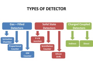
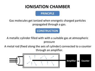
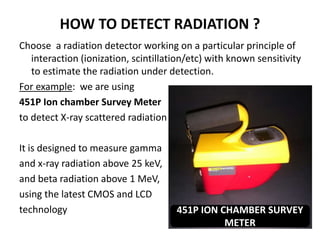
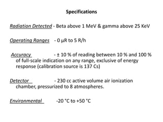
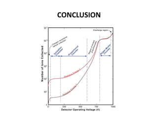


This document provides an overview of radiation detectors. It discusses why radiation detection is important, how radiation interacts with matter, common types of detectors like ionization chambers, proportional counters, and GM counters, and how detectors work to detect different types of radiation. Specific examples are given around using an ion chamber survey meter to detect x-rays. Key factors around detector selection, specifications, and operating principles are summarized.


