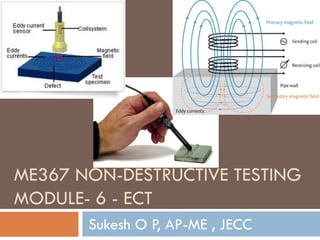
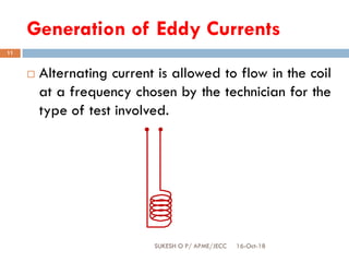
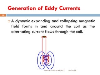
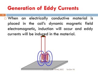
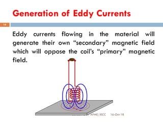
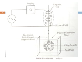
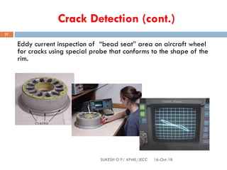
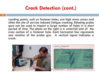
ME367 NON-DESTRUCTIVE TESTING
MODULE- 6 - ECT
Sukesh O P, AP-ME , JECC
ME357 Non-Destructive Testing
16-Oct-18SUKESH O P/ APME/JECC
2
Introduction to NDT- Visual Inspection- Liquid
Penetrant Inspection- Magnetic Particle
Inspection- Ultrasonic Testing- Radiography
Testing- Eddy Current Testing.
MODULE-6 (20%)
16-Oct-18SUKESH O P/ APME/JECC
3
Eddy Current Testing (ECT) - Principle, physics aspects of ECT like
conductivity, permeability, resistivity, inductance, inductive reactance,
impedance-Field factor and lift of effect, edge effect, end effect,
impedance plane diagram in brief, depth of penetration of ECT,
relation between frequency and depth of penetration in ECT -
equipment's and accessories, various application of ECT such as
conductivity measurement, hardness measurement, defect
detection-coating thickness measurement, advantages and
limitations of eddy current testing
16-Oct-18SUKESH O P/ APME/JECC
4
 Eddy current inspection is one of several
methods that use the principal of
“electromagnetism” as the basis for
conducting examinations. Several other
methods such as Remote Field Testing (RFT),
Flux Leakage and Barkhausen Noise also use
this principle.
16-Oct-18SUKESH O P/ APME/JECC
5
 Eddy currents are defined as oscillating electrical
currents induced in a conductive material by an
alternating magnetic field, due to electromagnetic
induction.
 ECT is used for sorting materials, measurement and
control of dimensions of tubes, sheets and rods, coating
thickness and pre-service and in-service examination of
heat exchanger tubes for detection of defects.
 Making use of electromagnetic induction to defect amd
characterize surface and sub-surface flaws in
conductive material.
Properties of eddy currents
16-Oct-18SUKESH O P/ APME/JECC
6
 Eddy current density decreases with the depth
exponentially. This phenomenon is known as the skin
effect.
 Eddy current are closed loops of induced current
circulating in planes perpendicular to the magnetic
flux.
 Eddy currents normally travel parallel to the coil’s
windings and the flow is limited to the area of
inducing magnetic field and perpendicular to the
axis of the coils flux field.
Electromagnetic Induction
16-Oct-18SUKESH O P/ APME/JECC
7
 Eddy currents are created through a process
called electromagnetic induction.
 When alternating current is applied to the
conductor, such as copper wire, a magnetic
field develops in and around the conductor.
 This magnetic field expands as the alternating
current rises to maximum and collapses as the
current is reduced to zero.
Electromagnetic Induction
16-Oct-18SUKESH O P/ APME/JECC
8
Generation of Eddy Currents
16-Oct-18SUKESH O P/ APME/JECC
9
Generation of Eddy Currents
16-Oct-18SUKESH O P/ APME/JECC
10
Generation of Eddy Currents
16-Oct-18SUKESH O P/ APME/JECC
11
 Alternating current is allowed to flow in the coil
at a frequency chosen by the technician for the
type of test involved.
Generation of Eddy Currents
16-Oct-18SUKESH O P/ APME/JECC
12
 A dynamic expanding and collapsing magnetic
field forms in and around the coil as the
alternating current flows through the coil.
Generation of Eddy Currents
16-Oct-18SUKESH O P/ APME/JECC
13
 When an electrically conductive material is
placed in the coil’s dynamic magnetic field
electromagnetic, induction will occur and eddy
currents will be induced in the material.
Generation of Eddy Currents
16-Oct-18SUKESH O P/ APME/JECC
14
Eddy currents flowing in the material will
generate their own “secondary” magnetic field
which will oppose the coil’s “primary” magnetic
field.
Generation of Eddy Currents
16-Oct-18SUKESH O P/ APME/JECC
15
 This entire electromagnetic induction process to
produce eddy currents may occur from several
hundred to several million times each second
depending upon inspection frequency.
Generation of Eddy Currents
16-Oct-18SUKESH O P/ APME/JECC
16
Principle of EDDY CURRENT TESTING
16-Oct-18SUKESH O P/ APME/JECC
17
 An alternating current (A.C) of frequency 1kHz – 2MHz
is made to flow in a coil which in turn, produces an
alternating magnetic field around it.
 This coil when brought close to the electrically
conducting surface of a metallic material to be
inspected, induces an eddy current flow in the material
due to electromagnetic induction.
 These eddy currents are generally parallel to the coil
winding. The presence of any defect or discontinuity in
the material disturbs the eddy current flow.
16-Oct-18SUKESH O P/ APME/JECC
18
LIFT OFF EFFECT
16-Oct-18SUKESH O P/ APME/JECC
19
 The distance between a surface coil and the test
surface is called proximity or lift off.
 Since flux density decreases exponentially with
distance from the test coil, the amount of lift or
separation between the coil and test specimen has
a significant effect on sensitivity.
 Close coupling increases the sensitivity to lift off
effect, noise due to probe nobbles, when encircling
coils are used. Lift off is equivalent to fill factor.
EDGE EFFECT
16-Oct-18SUKESH O P/ APME/JECC
20
 This refers to the effect that the components edge
or shape changes in geometry due to the eddy
currents.
 This can be neglected by placing a balancing
probe near to edge and scanning at the distance.
 Edge effect is phenomenon that occurs when an
inspection coil is at the end of the test piece.
 In order to avoid confusion with flaws, inspection is
limited near the edges.
FILL FACTOR
16-Oct-18SUKESH O P/ APME/JECC
21
 It is number which measures how well the test piece fills
the coil in external encircling probes,
 Fill factor= ie,
 Fill facor is the ratio of the cross sectional area of the
test piece and area of the coil section.
 It is necessary that the coil wires be as close as possible
to the test piece, in order to have a greater response
potential to cracks.
Fill factor should be as near as unity
END EFFECT
16-Oct-18SUKESH O P/ APME/JECC
22
 End effect is defined as the disturbance of the
magnetic field eddy current distribution, impedance
due to proximity of the coil to an abrupt change in
geometry.
 The end effect is common for cylindrical parts being
inspected with encircling or inside diameter bobbin
coils.
DEPTH OF PENETRATION
16-Oct-18SUKESH O P/ APME/JECC
23
 Eddy current concentrates near to the surface adjacent
to an excitation coil and their strength decreases with
distance from the coil.
 Skin effect arises when the eddy current flowing in the
test object at any depth produces magnetic fields which
oppose the primary field, thus reducing the net
magnetic flux and causing a decrease in eddy current
flow as the depth increases.
 It is mathematically convenient to define the standard
depth of penetration where the eddy current is 37% of
its surface value.
APPLICATIONS OF ECT
16-Oct-18SUKESH O P/ APME/JECC
24
1. Detection of discontinuities / surface breaking
cracks.
2. Conductivity measurement.
3. Inspection of tube.
4. Thickness measurement.
1. Detection of discontinuities
16-Oct-18SUKESH O P/ APME/JECC
25
 Defects such as cracks are detected when they disrupt
the path of eddy currents and weaken their strength.
 The sensitivity of ECT to detect surface discontinuities
depends on the factors such as type of material,
surface finish and condition of material, the design of
the probe.
 For surface flaws, the frequency should be as high as
possible for maximum resolution and high sensitivity.
 For subsurface flaws, lower frequencies are preferred
to set the required depth of penetration and this results
in less sensitivity.
16-Oct-18SUKESH O P/ APME/JECC
26
1. Selection of instrument and probe: the instrument
includes the basic devices such as oscillator,
probe/coil, signal processing and display. To test
surface cracks, pancake probe or surface probe is
preferred.
2. Selection of frequency to produce the desired depth
of penetration: depth of penetration depends on
frequency, conductivity and permeability. High
frequency is used for surface cracks and low frequency
is used to locate deeper cracks.
16-Oct-18SUKESH O P/ APME/JECC
27
 3. placing the coil probe and setting the instrument to
Null point: place the coil(probe) on the surface of the
component to be tested and set the instrument to null
point.
 4. scanning the surface by moving the probe in a
pattern : when the probe is moved over the surface of
the specimen, eddy current strength is altered due to
presence of crack.
 Depending on the density and phase lag of interrupted
eddy current circulation, signal response is displayed
through impedance plane.
16-Oct-18SUKESH O P/ APME/JECC
28
5. Monitoring the signal for a change in impedance:
with increasing depth of crack from the test surface,
the impedance locations are:
 Never to the surface
 Crack at greater depth
The direction of movement of the signal curve reveals the
possible discontinuity in the material.
Crack Detection
Crack detection is one of the primary uses of eddy current
inspection. Cracks cause a disruption in the circular flow patterns
of the eddy currents and weaken their strength. This change in
strength at the crack location can be detected.
Magnetic Field
From Test Coil
Magnetic Field
From
Eddy Currents
Eddy Currents
Crack
16-Oct-18SUKESH O P/ APME/JECC
29
Crack Detection (cont.)
Eddy current inspection is exceptionally well suited for the
detection of cracks, with an especially high sensitivity to detection
of surface breaking cracks.
16-Oct-18SUKESH O P/ APME/JECC
30
Crack Detection (cont.)
Eddy current inspection of “bead seat” area on aircraft wheel
for cracks using special probe that conforms to the shape of the
rim.
16-Oct-18SUKESH O P/ APME/JECC
31
Crack Detection (cont.)
Loading points, such as fastener holes, are high stress areas and
often the site of service induced fatigue cracking. Rotating probe
guns can be used to inspect a large number of holes in a short
period of time. The photo on the right is a waterfall plot of the
cross section of a fastener hole. Each horizontal line represents
one rotation of the probe gun. A vertical signal indicates a
crack.
16-Oct-18SUKESH O P/ APME/JECC
32
2. Conductivity Measurement
16-Oct-18SUKESH O P/ APME/JECC
33
 The value of the electrical conductivity of a material
depends on several factors such as chemical
composition and the stress state of its crystalline
structure.
 Electrical conductivity information can be used for
sorting metals, checking for proper heat treatment
and inspecting for heat damage.
 For non magnetic materials, the change in
impedance of the coil can be correlated directly to
the conductivity of the material.
Monitoring Conductivity and Permeability
Variations
Eddy current inspection is sensitive to changes in a material’s
electrical conductivity and magnetic permeability. This
“sensitivity” allows the inspection method to be used for such
inspection procedures as:
• Material Identification
• Material Sorting
• Determination of heat damage
• Cladding and plating thickness measurement
• Heat treatment monitoring
16-Oct-18SUKESH O P/ APME/JECC
34
3. Inspection on Tube
16-Oct-18SUKESH O P/ APME/JECC
35
 ECT is often used to detect corrosion, erosion, cracking
and other changes in tubing.
 Heat exchangers and steam generators, which are used
in power plants, have many tubes which must be
prevented from leaking.
 A technique that is often used involves feeding a
differential bobbin probe into the individual tube of the
heat exchanger.
 When the corrosion is on the outside surface of the tube,
the depth of corrosion is indicated by a shift in the
phase lag.
Material Thickness Measurement
 Thickness measurements are possible with eddy current
inspection within certain limitations.
 Only a certain amount of eddy currents can form in a
given volume of material.
 Therefore, thicker materials will support more eddy
currents than thinner materials.
 The strength (amount) of eddy currents can be measured
and related to the material thickness.
Eddy Currents
Magnetic Field
From Probe
Test
Material
16-Oct-18SUKESH O P/ APME/JECC
36
Material Thickness Measurement (cont.)
Eddy current inspection is often used in the aviation
industries to detect material loss due to corrosion and
erosion.
16-Oct-18SUKESH O P/ APME/JECC
37
Material Thickness Measurement (cont.)
Eddy current inspection is used extensively to inspect
tubing at power generation and petrochemical facilities for
corrosion and erosion.
16-Oct-18SUKESH O P/ APME/JECC
38
Nonconductive Coating Measurement
Nonconductive coatings on electrically conductive substrates
can be measured very accurately with eddy current
inspection. (Accuracy of less that one mil is not uncommon.)
Conductive
Base Metal
Nonconductive
Coating
Eddy Currents
 The coating displaces the eddy current probe from the conductive
base material and this weaken the strength of the eddy currents.
 This reduction in strength can be measured and related to coating
thickness.
16-Oct-18SUKESH O P/ APME/JECC
39
Nonconductive Coating Measurement
(cont.)
The photo to the left shows an aircraft panel paint thickness
inspection. On the right, the display of a digital eddy current
inspection instrument shows the different signals obtained
by measuring eight different thicknesses of paint on
aluminum.
Increasing paint
thickness
16-Oct-18SUKESH O P/ APME/JECC
40
• Sensitive to small cracks and other defects
• Detects surface and near surface defects
• Inspection gives immediate results
• Equipment is very portable
• Method can be used for much more than flaw detection
• Minimum part preparation is required
• Test probe does not need to contact the part
• Inspects complex shapes and sizes of conductive materials
Advantages of ECT
16-Oct-18SUKESH O P/ APME/JECC41
• Only conductive materials can be inspected
• Surface must be accessible to the probe
• Skill and training required is more extensive than other techniques
• Surface finish and roughness may interfere
• Reference standards needed for setup
• Depth of penetration is limited
• Flaws such as delaminations that lie parallel to the probe coil winding and probe
scan direction are undetectable
Limitations of ECT
16-Oct-18SUKESH O P/ APME/JECC42

Eddy Current Testing (ECT)- NDT

  • 1.
    ME367 NON-DESTRUCTIVE TESTING MODULE-6 - ECT Sukesh O P, AP-ME , JECC
  • 2.
    ME357 Non-Destructive Testing 16-Oct-18SUKESHO P/ APME/JECC 2 Introduction to NDT- Visual Inspection- Liquid Penetrant Inspection- Magnetic Particle Inspection- Ultrasonic Testing- Radiography Testing- Eddy Current Testing.
  • 3.
    MODULE-6 (20%) 16-Oct-18SUKESH OP/ APME/JECC 3 Eddy Current Testing (ECT) - Principle, physics aspects of ECT like conductivity, permeability, resistivity, inductance, inductive reactance, impedance-Field factor and lift of effect, edge effect, end effect, impedance plane diagram in brief, depth of penetration of ECT, relation between frequency and depth of penetration in ECT - equipment's and accessories, various application of ECT such as conductivity measurement, hardness measurement, defect detection-coating thickness measurement, advantages and limitations of eddy current testing
  • 4.
    16-Oct-18SUKESH O P/APME/JECC 4  Eddy current inspection is one of several methods that use the principal of “electromagnetism” as the basis for conducting examinations. Several other methods such as Remote Field Testing (RFT), Flux Leakage and Barkhausen Noise also use this principle.
  • 5.
    16-Oct-18SUKESH O P/APME/JECC 5  Eddy currents are defined as oscillating electrical currents induced in a conductive material by an alternating magnetic field, due to electromagnetic induction.  ECT is used for sorting materials, measurement and control of dimensions of tubes, sheets and rods, coating thickness and pre-service and in-service examination of heat exchanger tubes for detection of defects.  Making use of electromagnetic induction to defect amd characterize surface and sub-surface flaws in conductive material.
  • 6.
    Properties of eddycurrents 16-Oct-18SUKESH O P/ APME/JECC 6  Eddy current density decreases with the depth exponentially. This phenomenon is known as the skin effect.  Eddy current are closed loops of induced current circulating in planes perpendicular to the magnetic flux.  Eddy currents normally travel parallel to the coil’s windings and the flow is limited to the area of inducing magnetic field and perpendicular to the axis of the coils flux field.
  • 7.
    Electromagnetic Induction 16-Oct-18SUKESH OP/ APME/JECC 7  Eddy currents are created through a process called electromagnetic induction.  When alternating current is applied to the conductor, such as copper wire, a magnetic field develops in and around the conductor.  This magnetic field expands as the alternating current rises to maximum and collapses as the current is reduced to zero.
  • 8.
  • 9.
    Generation of EddyCurrents 16-Oct-18SUKESH O P/ APME/JECC 9
  • 10.
    Generation of EddyCurrents 16-Oct-18SUKESH O P/ APME/JECC 10
  • 11.
    Generation of EddyCurrents 16-Oct-18SUKESH O P/ APME/JECC 11  Alternating current is allowed to flow in the coil at a frequency chosen by the technician for the type of test involved.
  • 12.
    Generation of EddyCurrents 16-Oct-18SUKESH O P/ APME/JECC 12  A dynamic expanding and collapsing magnetic field forms in and around the coil as the alternating current flows through the coil.
  • 13.
    Generation of EddyCurrents 16-Oct-18SUKESH O P/ APME/JECC 13  When an electrically conductive material is placed in the coil’s dynamic magnetic field electromagnetic, induction will occur and eddy currents will be induced in the material.
  • 14.
    Generation of EddyCurrents 16-Oct-18SUKESH O P/ APME/JECC 14 Eddy currents flowing in the material will generate their own “secondary” magnetic field which will oppose the coil’s “primary” magnetic field.
  • 15.
    Generation of EddyCurrents 16-Oct-18SUKESH O P/ APME/JECC 15  This entire electromagnetic induction process to produce eddy currents may occur from several hundred to several million times each second depending upon inspection frequency.
  • 16.
    Generation of EddyCurrents 16-Oct-18SUKESH O P/ APME/JECC 16
  • 17.
    Principle of EDDYCURRENT TESTING 16-Oct-18SUKESH O P/ APME/JECC 17  An alternating current (A.C) of frequency 1kHz – 2MHz is made to flow in a coil which in turn, produces an alternating magnetic field around it.  This coil when brought close to the electrically conducting surface of a metallic material to be inspected, induces an eddy current flow in the material due to electromagnetic induction.  These eddy currents are generally parallel to the coil winding. The presence of any defect or discontinuity in the material disturbs the eddy current flow.
  • 18.
  • 19.
    LIFT OFF EFFECT 16-Oct-18SUKESHO P/ APME/JECC 19  The distance between a surface coil and the test surface is called proximity or lift off.  Since flux density decreases exponentially with distance from the test coil, the amount of lift or separation between the coil and test specimen has a significant effect on sensitivity.  Close coupling increases the sensitivity to lift off effect, noise due to probe nobbles, when encircling coils are used. Lift off is equivalent to fill factor.
  • 20.
    EDGE EFFECT 16-Oct-18SUKESH OP/ APME/JECC 20  This refers to the effect that the components edge or shape changes in geometry due to the eddy currents.  This can be neglected by placing a balancing probe near to edge and scanning at the distance.  Edge effect is phenomenon that occurs when an inspection coil is at the end of the test piece.  In order to avoid confusion with flaws, inspection is limited near the edges.
  • 21.
    FILL FACTOR 16-Oct-18SUKESH OP/ APME/JECC 21  It is number which measures how well the test piece fills the coil in external encircling probes,  Fill factor= ie,  Fill facor is the ratio of the cross sectional area of the test piece and area of the coil section.  It is necessary that the coil wires be as close as possible to the test piece, in order to have a greater response potential to cracks. Fill factor should be as near as unity
  • 22.
    END EFFECT 16-Oct-18SUKESH OP/ APME/JECC 22  End effect is defined as the disturbance of the magnetic field eddy current distribution, impedance due to proximity of the coil to an abrupt change in geometry.  The end effect is common for cylindrical parts being inspected with encircling or inside diameter bobbin coils.
  • 23.
    DEPTH OF PENETRATION 16-Oct-18SUKESHO P/ APME/JECC 23  Eddy current concentrates near to the surface adjacent to an excitation coil and their strength decreases with distance from the coil.  Skin effect arises when the eddy current flowing in the test object at any depth produces magnetic fields which oppose the primary field, thus reducing the net magnetic flux and causing a decrease in eddy current flow as the depth increases.  It is mathematically convenient to define the standard depth of penetration where the eddy current is 37% of its surface value.
  • 24.
    APPLICATIONS OF ECT 16-Oct-18SUKESHO P/ APME/JECC 24 1. Detection of discontinuities / surface breaking cracks. 2. Conductivity measurement. 3. Inspection of tube. 4. Thickness measurement.
  • 25.
    1. Detection ofdiscontinuities 16-Oct-18SUKESH O P/ APME/JECC 25  Defects such as cracks are detected when they disrupt the path of eddy currents and weaken their strength.  The sensitivity of ECT to detect surface discontinuities depends on the factors such as type of material, surface finish and condition of material, the design of the probe.  For surface flaws, the frequency should be as high as possible for maximum resolution and high sensitivity.  For subsurface flaws, lower frequencies are preferred to set the required depth of penetration and this results in less sensitivity.
  • 26.
    16-Oct-18SUKESH O P/APME/JECC 26 1. Selection of instrument and probe: the instrument includes the basic devices such as oscillator, probe/coil, signal processing and display. To test surface cracks, pancake probe or surface probe is preferred. 2. Selection of frequency to produce the desired depth of penetration: depth of penetration depends on frequency, conductivity and permeability. High frequency is used for surface cracks and low frequency is used to locate deeper cracks.
  • 27.
    16-Oct-18SUKESH O P/APME/JECC 27  3. placing the coil probe and setting the instrument to Null point: place the coil(probe) on the surface of the component to be tested and set the instrument to null point.  4. scanning the surface by moving the probe in a pattern : when the probe is moved over the surface of the specimen, eddy current strength is altered due to presence of crack.  Depending on the density and phase lag of interrupted eddy current circulation, signal response is displayed through impedance plane.
  • 28.
    16-Oct-18SUKESH O P/APME/JECC 28 5. Monitoring the signal for a change in impedance: with increasing depth of crack from the test surface, the impedance locations are:  Never to the surface  Crack at greater depth The direction of movement of the signal curve reveals the possible discontinuity in the material.
  • 29.
    Crack Detection Crack detectionis one of the primary uses of eddy current inspection. Cracks cause a disruption in the circular flow patterns of the eddy currents and weaken their strength. This change in strength at the crack location can be detected. Magnetic Field From Test Coil Magnetic Field From Eddy Currents Eddy Currents Crack 16-Oct-18SUKESH O P/ APME/JECC 29
  • 30.
    Crack Detection (cont.) Eddycurrent inspection is exceptionally well suited for the detection of cracks, with an especially high sensitivity to detection of surface breaking cracks. 16-Oct-18SUKESH O P/ APME/JECC 30
  • 31.
    Crack Detection (cont.) Eddycurrent inspection of “bead seat” area on aircraft wheel for cracks using special probe that conforms to the shape of the rim. 16-Oct-18SUKESH O P/ APME/JECC 31
  • 32.
    Crack Detection (cont.) Loadingpoints, such as fastener holes, are high stress areas and often the site of service induced fatigue cracking. Rotating probe guns can be used to inspect a large number of holes in a short period of time. The photo on the right is a waterfall plot of the cross section of a fastener hole. Each horizontal line represents one rotation of the probe gun. A vertical signal indicates a crack. 16-Oct-18SUKESH O P/ APME/JECC 32
  • 33.
    2. Conductivity Measurement 16-Oct-18SUKESHO P/ APME/JECC 33  The value of the electrical conductivity of a material depends on several factors such as chemical composition and the stress state of its crystalline structure.  Electrical conductivity information can be used for sorting metals, checking for proper heat treatment and inspecting for heat damage.  For non magnetic materials, the change in impedance of the coil can be correlated directly to the conductivity of the material.
  • 34.
    Monitoring Conductivity andPermeability Variations Eddy current inspection is sensitive to changes in a material’s electrical conductivity and magnetic permeability. This “sensitivity” allows the inspection method to be used for such inspection procedures as: • Material Identification • Material Sorting • Determination of heat damage • Cladding and plating thickness measurement • Heat treatment monitoring 16-Oct-18SUKESH O P/ APME/JECC 34
  • 35.
    3. Inspection onTube 16-Oct-18SUKESH O P/ APME/JECC 35  ECT is often used to detect corrosion, erosion, cracking and other changes in tubing.  Heat exchangers and steam generators, which are used in power plants, have many tubes which must be prevented from leaking.  A technique that is often used involves feeding a differential bobbin probe into the individual tube of the heat exchanger.  When the corrosion is on the outside surface of the tube, the depth of corrosion is indicated by a shift in the phase lag.
  • 36.
    Material Thickness Measurement Thickness measurements are possible with eddy current inspection within certain limitations.  Only a certain amount of eddy currents can form in a given volume of material.  Therefore, thicker materials will support more eddy currents than thinner materials.  The strength (amount) of eddy currents can be measured and related to the material thickness. Eddy Currents Magnetic Field From Probe Test Material 16-Oct-18SUKESH O P/ APME/JECC 36
  • 37.
    Material Thickness Measurement(cont.) Eddy current inspection is often used in the aviation industries to detect material loss due to corrosion and erosion. 16-Oct-18SUKESH O P/ APME/JECC 37
  • 38.
    Material Thickness Measurement(cont.) Eddy current inspection is used extensively to inspect tubing at power generation and petrochemical facilities for corrosion and erosion. 16-Oct-18SUKESH O P/ APME/JECC 38
  • 39.
    Nonconductive Coating Measurement Nonconductivecoatings on electrically conductive substrates can be measured very accurately with eddy current inspection. (Accuracy of less that one mil is not uncommon.) Conductive Base Metal Nonconductive Coating Eddy Currents  The coating displaces the eddy current probe from the conductive base material and this weaken the strength of the eddy currents.  This reduction in strength can be measured and related to coating thickness. 16-Oct-18SUKESH O P/ APME/JECC 39
  • 40.
    Nonconductive Coating Measurement (cont.) Thephoto to the left shows an aircraft panel paint thickness inspection. On the right, the display of a digital eddy current inspection instrument shows the different signals obtained by measuring eight different thicknesses of paint on aluminum. Increasing paint thickness 16-Oct-18SUKESH O P/ APME/JECC 40
  • 41.
    • Sensitive tosmall cracks and other defects • Detects surface and near surface defects • Inspection gives immediate results • Equipment is very portable • Method can be used for much more than flaw detection • Minimum part preparation is required • Test probe does not need to contact the part • Inspects complex shapes and sizes of conductive materials Advantages of ECT 16-Oct-18SUKESH O P/ APME/JECC41
  • 42.
    • Only conductivematerials can be inspected • Surface must be accessible to the probe • Skill and training required is more extensive than other techniques • Surface finish and roughness may interfere • Reference standards needed for setup • Depth of penetration is limited • Flaws such as delaminations that lie parallel to the probe coil winding and probe scan direction are undetectable Limitations of ECT 16-Oct-18SUKESH O P/ APME/JECC42