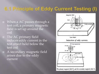
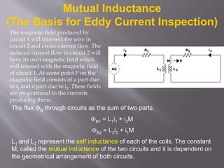
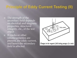
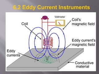
 Eddy current testing can be used on all electrically conducting
materials with a reasonably smooth surface.
 The test equipment consists of a generator (AC power supply), a
test coil and recording equipment, e.g. a galvanometer or an
oscilloscope
 Used for crack detection, material thickness measurement
(corrosion detection), sorting materials, coating thickness
measurement, metal detection, etc.
Electrical currents are generated in a conductive material by an induced alternating
magnetic field. The electrical currents are called eddy currents because the flow in
circles at and just below the surface of the material. Interruptions in the flow of eddy
currents, caused by imperfections, dimensional changes, or changes in the
material's conductive and permeability properties, can be detected with the proper
equipment.
 When a AC passes through a
test coil, a primary magnetic
field is set up around the
coil
 The AC primary field
induces eddy current in the
test object held below the
test coil
 A secondary magnetic field
arises due to the eddy
current
Mutual Inductance
(The Basis for Eddy Current Inspection)
The flux B through circuits as the sum of two parts.
B1 = L1i1 + i2M
B2 = L2i2 + i1M
L1 and L2 represent the self inductance of each of the coils. The constant
M, called the mutual inductance of the two circuits and it is dependent on
the geometrical arrangement of both circuits.
The magnetic field produced by
circuit 1 will intersect the wire in
circuit 2 and create current flow. The
induced current flow in circuit 2 will
have its own magnetic field which
will interact with the magnetic field
of circuit 1. At some point P on the
magnetic field consists of a part due
to i1 and a part due to i2. These fields
are proportional to the currents
producing them.
 The strength of the
secondary field depends
on electrical and magnetic
properties, structural
integrity, etc., of the test
object
 If cracks or other
inhomogeneities are
present, the eddy current,
and hence the secondary
field is affected.
 The changes in the
secondary field will be a
‘feedback’ to the primary
coil and affect the primary
current.
 The variations of the
primary current can be
easily detected by a simple
circuit which is zeroed
properly beforehand
Conductive
material
Coil
Coil's
magnetic field
Eddy
currents
Eddy current's
magnetic field
6.2 Eddy Current Instruments
Voltmeter
Eddy currents are closed loops of induced current circulating in planes
perpendicular to the magnetic flux. They normally travel parallel to the
coil's winding and flow is limited to the area of the inducing magnetic field.
Eddy currents concentrate near the surface adjacent to an excitation coil
and their strength decreases with distance from the coil as shown in the
image. Eddy current density decreases exponentially with depth. This
phenomenon is known as the skin effect.
Depth of Penetration
The depth at which eddy current density has decreased to 1/e, or about 37%
of the surface density, is called the standard depth of penetration ().
 The test coils are
commonly used in
three
configurations
 Surface probe
 Internal bobbin
probe
 Encircling probe
6.3 Result presentation
The impedance plane diagram is a
very useful way of displaying eddy
current data. The strength of the
eddy currents and the magnetic
permeability of the test material
cause the eddy current signal on
the impedance plane to react in a
variety of different ways.
•Crack Detection
•Material Thickness
Measurements
•Coating Thickness
Measurements
•Conductivity Measurements For:
•Material Identification
•Heat Damage Detection
•Case Depth Determination
•Heat Treatment Monitoring
6.4 Applications
Surface Breaking Cracks
Eddy current inspection is an excellent
method for detecting surface and near
surface defects when the probable defect
location and orientation is well known.
In the lower image, there is
a flaw under the right side
of the coil and it can be see
that the eddy currents are
weaker in this area.
Successful detection requires:
1. A knowledge of probable defect type, position,
and orientation.
2. Selection of the proper probe. The probe should
fit the geometry of the part and the coil must
produce eddy currents that will be disrupted by
the flaw.
3. Selection of a reasonable probe drive frequency.
For surface flaws, the frequency should be as
high as possible for maximum resolution and
high sensitivity. For subsurface flaws, lower
frequencies are necessary to get the required
depth of penetration.
 Mainly for automatic
production control
 Round bars, pipes, wires
and similar items are
generally inspected with
encircling probes
 Discontinuities and
dimensional changes can be
revealed
 In-situ monitoring of wires
used on cranes, elevators,
towing cables is also an
useful application
 Primarily for
examination of tubes
in heat exchangers
and oil pipes
 Become increasingly
popular due to the
wide acceptance of
the philosophy of
preventive
maintenance
•Sensitive to small cracks and other defects
•Detects surface and near surface defects
•Inspection gives immediate results
•Equipment is very portable
•Method can be used for much more than flaw detection
•Minimum part preparation is required
•Test probe does not need to contact the part
•Inspects complex shapes and sizes of conductive materials
6.5 Advantages of ET
•Only conductive materials can be inspected
•Surface must be accessible to the probe
•Skill and training required is more extensive than other techniques
•Surface finish and and roughness may interfere
•Reference standards needed for setup
•Depth of penetration is limited
•Flaws such as delaminations that lie parallel to the probe coil winding and
probe scan direction are undetectable
Limitations of ET

eddycurrenttesting.pdf

  • 2.
     Eddy currenttesting can be used on all electrically conducting materials with a reasonably smooth surface.  The test equipment consists of a generator (AC power supply), a test coil and recording equipment, e.g. a galvanometer or an oscilloscope  Used for crack detection, material thickness measurement (corrosion detection), sorting materials, coating thickness measurement, metal detection, etc. Electrical currents are generated in a conductive material by an induced alternating magnetic field. The electrical currents are called eddy currents because the flow in circles at and just below the surface of the material. Interruptions in the flow of eddy currents, caused by imperfections, dimensional changes, or changes in the material's conductive and permeability properties, can be detected with the proper equipment.
  • 3.
     When aAC passes through a test coil, a primary magnetic field is set up around the coil  The AC primary field induces eddy current in the test object held below the test coil  A secondary magnetic field arises due to the eddy current
  • 4.
    Mutual Inductance (The Basisfor Eddy Current Inspection) The flux B through circuits as the sum of two parts. B1 = L1i1 + i2M B2 = L2i2 + i1M L1 and L2 represent the self inductance of each of the coils. The constant M, called the mutual inductance of the two circuits and it is dependent on the geometrical arrangement of both circuits. The magnetic field produced by circuit 1 will intersect the wire in circuit 2 and create current flow. The induced current flow in circuit 2 will have its own magnetic field which will interact with the magnetic field of circuit 1. At some point P on the magnetic field consists of a part due to i1 and a part due to i2. These fields are proportional to the currents producing them.
  • 5.
     The strengthof the secondary field depends on electrical and magnetic properties, structural integrity, etc., of the test object  If cracks or other inhomogeneities are present, the eddy current, and hence the secondary field is affected.
  • 6.
     The changesin the secondary field will be a ‘feedback’ to the primary coil and affect the primary current.  The variations of the primary current can be easily detected by a simple circuit which is zeroed properly beforehand
  • 7.
  • 8.
    Eddy currents areclosed loops of induced current circulating in planes perpendicular to the magnetic flux. They normally travel parallel to the coil's winding and flow is limited to the area of the inducing magnetic field. Eddy currents concentrate near the surface adjacent to an excitation coil and their strength decreases with distance from the coil as shown in the image. Eddy current density decreases exponentially with depth. This phenomenon is known as the skin effect. Depth of Penetration The depth at which eddy current density has decreased to 1/e, or about 37% of the surface density, is called the standard depth of penetration ().
  • 9.
     The testcoils are commonly used in three configurations  Surface probe  Internal bobbin probe  Encircling probe
  • 10.
    6.3 Result presentation Theimpedance plane diagram is a very useful way of displaying eddy current data. The strength of the eddy currents and the magnetic permeability of the test material cause the eddy current signal on the impedance plane to react in a variety of different ways.
  • 11.
    •Crack Detection •Material Thickness Measurements •CoatingThickness Measurements •Conductivity Measurements For: •Material Identification •Heat Damage Detection •Case Depth Determination •Heat Treatment Monitoring 6.4 Applications
  • 12.
    Surface Breaking Cracks Eddycurrent inspection is an excellent method for detecting surface and near surface defects when the probable defect location and orientation is well known. In the lower image, there is a flaw under the right side of the coil and it can be see that the eddy currents are weaker in this area. Successful detection requires: 1. A knowledge of probable defect type, position, and orientation. 2. Selection of the proper probe. The probe should fit the geometry of the part and the coil must produce eddy currents that will be disrupted by the flaw. 3. Selection of a reasonable probe drive frequency. For surface flaws, the frequency should be as high as possible for maximum resolution and high sensitivity. For subsurface flaws, lower frequencies are necessary to get the required depth of penetration.
  • 13.
     Mainly forautomatic production control  Round bars, pipes, wires and similar items are generally inspected with encircling probes  Discontinuities and dimensional changes can be revealed  In-situ monitoring of wires used on cranes, elevators, towing cables is also an useful application
  • 14.
     Primarily for examinationof tubes in heat exchangers and oil pipes  Become increasingly popular due to the wide acceptance of the philosophy of preventive maintenance
  • 16.
    •Sensitive to smallcracks and other defects •Detects surface and near surface defects •Inspection gives immediate results •Equipment is very portable •Method can be used for much more than flaw detection •Minimum part preparation is required •Test probe does not need to contact the part •Inspects complex shapes and sizes of conductive materials 6.5 Advantages of ET
  • 17.
    •Only conductive materialscan be inspected •Surface must be accessible to the probe •Skill and training required is more extensive than other techniques •Surface finish and and roughness may interfere •Reference standards needed for setup •Depth of penetration is limited •Flaws such as delaminations that lie parallel to the probe coil winding and probe scan direction are undetectable Limitations of ET