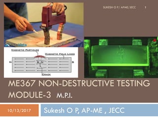
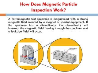
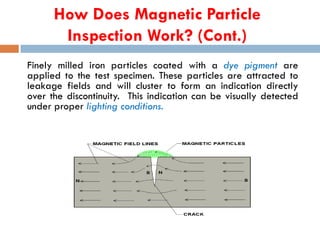
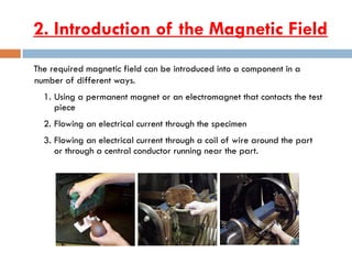
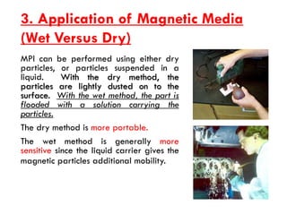
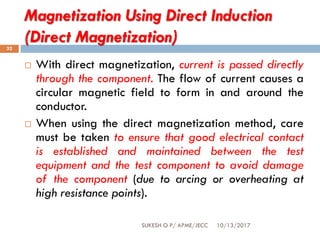
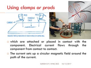
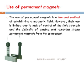
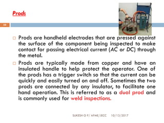
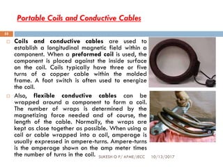
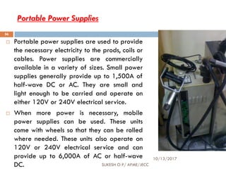
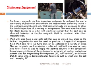
2. ME357 Non-Destructive Testing
10/13/2017SUKESH O P/ APME/JECC
2
Introduction to NDT- Visual Inspection- Liquid
Penetrant Inspection- Magnetic
Particle Inspection-
Ultrasonic Testing- Radiography Testing- Eddy
Current Testing.
3. MODULE-3
10/13/2017SUKESH O P/ APME/JECC
3
Magnetic Particle Inspection (MPI)- Principles of MPI,
basic physics of magnetism, permeability, flux density,
cohesive force, magnetizing force, rentivity, residual
magnetism , Methods of magnetization, magnetization
techniques such as head shot technique, cold shot
technique, central conductor testing, magnetization using
products using yokes, direct and indirect method of
magnetization, continuous testing of MPI, residual
technique of MPI, system sensitivity, checking devices in
MPI- Interpretation of MPI, indications, advantage and
limitation of MPI.
4. INTRODUCTION
10/13/2017SUKESH O P/ APME/JECC
4
MPI is governed by the laws of magnetism and is therefore
restricted to the inspection of materials that can support magnetic
flux lines, metals can be classified as ferromagnetic, paramagnetic, or
diamagnetic.
Ferromagnetic metals are those that are strongly attracted to a
magnet and can become easily magnetized. Ex: iron, nickel, cobalt.
Paramagnetic metals such as austenitic stainless steel are very
weakly attracted by magnetic forces of attraction and cannot be
magnetized. Ex: Aluminum
Diamagnetic metals which have a weak, negative susceptibility to
magnetic fields. Diamagnetic materials are slightly repelled by a
magnetic field and the material does not retain the magnetic
properties when the external field is removed. Ex: copper, silver,
gold
MPI- it is not applicable to
non-magnetic materials
5. INTRODUCTION
10/13/2017SUKESH O P/ APME/JECC
5
The only requirement For the inspection through this
technique is that the components being inspected must be
made of a ferromagnetic material (a materials that can be
magnetized) such as iron, nickel, cobalt, or some of their
alloys.
The method is used to inspect a variety of product forms
including castings, forgings, and weldments.
Many different industries use MPI such as structural steel,
automotive, petrochemical, power generation, and
aerospace industries.
Underwater inspection is another area where magnetic
particle inspection may be used to test items such as
offshore structures and underwater pipelines.
6. Introduction to Magnetism
10/13/2017SUKESH O P/ APME/JECC
6
Magnetism is the ability of matter to attract
other matter to itself. Objects that possess the
property of magnetism are said to be magnetic
or magnetized and magnetic lines of force can
be found in and around the objects. A magnetic
pole is a point where the a magnetic line of
force exits or enters a material.
Magnetic field lines:
• Form complete loops.
• Do not cross.
• Follow the path of least resistance.
• All have the same strength.
• Have a direction such that they cause
poles to attract or repel.
Magnetic lines of force
around a bar magnet
Opposite poles
attracting Similar poles repelling
7. Ferromagnetic Materials
10/13/2017
SUKESH O P/ APME/JECC
7
A material is considered ferromagnetic if it can be
magnetized. Materials with a significant Iron, nickel or
cobalt content are generally ferromagnetic.
Ferromagnetic materials are made up of many regions
in which the magnetic fields of atoms are aligned.
These regions are call magnetic domains.
Magnetic domains point randomly in demagnetized
material, but can be aligned using electrical current or
an external magnetic field to magnetize the material.
Demagnetized
Magnetized
8. How Does Magnetic Particle
Inspection Work?
A ferromagnetic test specimen is magnetized with a strong
magnetic field created by a magnet or special equipment. If
the specimen has a discontinuity, the discontinuity will
interrupt the magnetic field flowing through the specimen and
a leakage field will occur.
9. How Does Magnetic Particle
Inspection Work? (Cont.)
Finely milled iron particles coated with a dye pigment are
applied to the test specimen. These particles are attracted to
leakage fields and will cluster to form an indication directly
over the discontinuity. This indication can be visually detected
under proper lighting conditions.
10. Basic Procedure- MPI
Basic steps involved:
1.Component pre-cleaning
2.Introduction of magnetic field
3.Application of magnetic media
4.Interpretation of magnetic particle indications
11. 1. Pre-cleaning
When inspecting a test part with the magnetic particle
method it is essential for the particles to have an unimpeded
path for migration to both strong and weak leakage fields
alike. The part’s surface should be clean and dry before
inspection.
Contaminants such as oil,
grease, or scale may not
only prevent particles from
being attracted to leakage
fields, they may also
interfere with interpretation
of indications.
12. 2. Introduction of the Magnetic Field
The required magnetic field can be introduced into a component in a
number of different ways.
1. Using a permanent magnet or an electromagnet that contacts the test
piece
2. Flowing an electrical current through the specimen
3. Flowing an electrical current through a coil of wire around the part
or through a central conductor running near the part.
13. 3. Application of Magnetic Media
(Wet Versus Dry)
MPI can be performed using either dry
particles, or particles suspended in a
liquid. With the dry method, the
particles are lightly dusted on to the
surface. With the wet method, the part is
flooded with a solution carrying the
particles.
The dry method is more portable.
The wet method is generally more
sensitive since the liquid carrier gives the
magnetic particles additional mobility.
14. 4. Interpretation of Indications
After applying the magnetic field, indications that form must
interpreted. This process requires that the inspector
distinguish between relevant and non-relevant indications.
15. Crane Hook with Service Induced Crack
Fluorescent, Wet Particle Method
20. Large Bolt with Service Induced Crack
Fluorescent, Wet Particle Method
21. Crank Shaft with Service Induced Crack Near Lube Hole
Fluorescent, Wet Particle Method
22. Lack of Fusion in SMAW Weld
Visible, Dry Powder Method
Indication
23. Toe Crack in SMAW Weld
Visible, Dry Powder Method
24. Throat and Toe Cracks in
Partially Ground Weld
Visible, Dry Powder Method
25. Magnetic Particles/ media
The particles used in magnetic particle testing are made of ferromagnetic
materials, usually combinations of iron and iron oxides, having a high
permeability and low retentivity. Particles having high permeability are
easily attracted to and magnetized by the low-
level leakage fields at discontinuities.
Low retentivity is required to prevent the particles from being
permanently magnetized. Strongly retentive particles will cling
together and to any magnetic surface, resulting in reduced particle
mobility and increased background accumulation.
A common particle used to detect cracks is iron oxide, for both dry and wet
system/ style
26. Dry Magnetic Particles
Magnetic particles come in a variety of colors. A color that
produces a high level of contrast against the background
should be used.
27. Wet Magnetic Particles
Wet particles are typically supplied as
visible or fluorescent. Visible particles are
viewed under normal white light and
fluorescent particles are viewed under
black light.
28. 10/13/2017SUKESH O P/ APME/JECC
28
Dry
● Common, relatively cheap
● Generally applied to rougher
surfaces
● Particle types
○ Elongated - align well
with magnetic fields
○ Rounded - move freely
across a surface
Wet
● More expensive, accurate
● Painted or sprayed onto
surfaces
● Wet dye classifications
○ Light (UV or fluorescent)
○ Removal type (water,
solvent, or emulsifier)
29. Types of Magnetization
Two general types of magnetic fields (longitudinal and
circular) may be established within the specimen. The type of
magnetic field established is determined by the method used
to magnetize the specimen.
• A longitudinal magnetic field has magnetic lines
of force that run parallel to the long axis of the
part.
• A circular magnetic field has magnetic lines of
force that run circumferentially around the
perimeter of a part.
30. Importance of Magnetic Field Direction
Being able to magnetize the part in two
directions is important because the best
detection of defects occurs when the lines of
magnetic force are established at right angles
to the longest dimension of the defect. This
orientation creates the largest disruption of the
magnetic field within the part and the greatest
flux leakage at the surface of the part. An
orientation of 45 to 90 degrees between the
magnetic field and the defect is necessary to
form an indication.
Since defects may occur in
various and unknown
directions, each part is
normally magnetized in two
directions at right angles to
each other.
Flux Leakage
No Flux Leakage
31. Methods of magnetization
10/13/2017SUKESH O P/ APME/JECC
31
There are a variety of methods that can be used to
establish a magnetic field in a component for
evaluation using magnetic particle inspection. It is
common to classify the magnetizing methods as
either direct or indirect.
32. Magnetization Using Direct Induction
(Direct Magnetization)
10/13/2017SUKESH O P/ APME/JECC
32
With direct magnetization, current is passed directly
through the component. The flow of current causes a
circular magnetic field to form in and around the
conductor.
When using the direct magnetization method, care
must be taken to ensure that good electrical contact
is established and maintained between the test
equipment and the test component to avoid damage
of the component (due to arcing or overheating at
high resistance points).
33. Clamping the component between two
electrical contacts(HEAD SHOT Method)
10/13/2017SUKESH O P/ APME/JECC
33
Current is passed through the component and a circular
magnetic field is established in and around the component.
When the magnetizing current is stopped, a residual
magnetic field will remain within the component.
The strength of the induced magnetic field is proportional
to the amount of current passed through the component.
34. Using clamps or prods
10/13/2017SUKESH O P/ APME/JECC
34
which are attached or placed in contact with the
component. Electrical current flows through the
component from contact to contact.
The current sets up a circular magnetic field around the
path of the current.
35. Magnetization Using Indirect Induction
(Indirect Magnetization)
10/13/2017SUKESH O P/ APME/JECC
35
Indirect magnetization is accomplished by using a
strong external magnetic field to establish a magnetic
field within the component. As with direct
magnetization, there are several ways that indirect
magnetization can be accomplished.
36. Use of permanent magnets
10/13/2017SUKESH O P/ APME/JECC
36
The use of permanent magnets is a low cost method
of establishing a magnetic field. However, their use
is limited due to lack of control of the field strength
and the difficulty of placing and removing strong
permanent magnets from the component.
37. Electromagnets(using
yokes)
10/13/2017SUKESH O P/ APME/JECC
37
Electromagnets in the form of an adjustable horseshoe magnet
(called a yoke) eliminate the problems associated with
permanent magnets and are used extensively in industry.
Electromagnets only exhibit a magnetic flux when electric
current is flowing around the soft iron core. When the magnet
is placed on the component, a magnetic field is established
between the north and south poles of the magnet.
38. Central conductor
magnetization
10/13/2017SUKESH O P/ APME/JECC
38
Another way of indirectly inducting a magnetic field in
a material is by using the magnetic field of a current
carrying conductor. A circular magnetic field can be
established in cylindrical components by using a central
conductor.
Typically, one or more cylindrical components are hung
from a solid copper bar running through the inside
diameter. Current is passed through the copper bar and
the resulting circular magnetic field establishes a
magnetic field within the test components.
39. Use of coils and solenoids
10/13/2017SUKESH O P/ APME/JECC
39
When the length of a component is several times larger
than its diameter, a longitudinal magnetic field can be
established in the component.
The component is placed longitudinally in the
concentrated magnetic field that fills the center of a
coil or solenoid. This magnetization technique is often
referred to as a "coil shot".
40. Longitudinal &Circular Magnetic Fields
Longitudinal
1. Permanent magnets
2. Electromagnetic yokes
3. Using a Coil(COIL SHOT)
Circular
1. Clamping the component
between two
electrical contacts(HEAD SHOT)
2. Using clamps or prods
3. Central conductor magnetization
41. Types of Magnetizing Current
10/13/2017SUKESH O P/ APME/JECC
41
As mentioned previously, electric current is often
used to establish the magnetic field in components
during magnetic particle inspection. Alternating
current (AC) and direct current (DC) are the two
basic types of current commonly used.
42. 1. Direct Current
10/13/2017SUKESH O P/ APME/JECC
42
Direct current (DC) flows continuously in one direction at a
constant voltage. A battery is the most common source of
direct current.
The current is said to flow from the positive to the
negative terminal, though electrons flow in the opposite
direction.
DC is very desirable when inspecting for subsurface
defects because DC generates a magnetic field that
penetrates deeper into the material.
In ferromagnetic materials, the magnetic field produced
by DC generally penetrates the entire cross-section of
the component.
43. 2. Alternating Current
10/13/2017SUKESH O P/ APME/JECC
43
Alternating current (AC) reverses in direction at a rate of 50
or 60 cycles per second. Since AC is readily available in most
facilities, it is convenient to make use of it for magnetic
particle inspection.
However, when AC is used to induce a magnetic field in
ferromagnetic materials, the magnetic field will be limited to a
thin layer at the surface of the component. This phenomenon
is known as the "skin effect" and occurs because the
changing magnetic field generates eddy currents in the test
object.
The eddy currents produce a magnetic field that opposes the
primary field, thus reducing the net magnetic flux below the
surface. Therefore, it is recommended that AC be used only
when the inspection is limited to surface defects.
44. 3. Rectified Alternating Current
10/13/2017SUKESH O P/ APME/JECC
44
Clearly, the skin effect limits the use of AC since
many inspection applications call for the detection
of subsurface defects.
Luckily, AC can be converted to current that is very
much like DC through the process of rectification.
With the use of rectifiers, the reversing AC can be
converted to a one directional current.
46. Half Wave Rectified Alternating Current (HWAC)
10/13/2017SUKESH O P/ APME/JECC
46
When single phase alternating current is passed through a rectifier,
current is allowed to flow in only one direction.
The reverse half of each cycle is blocked out so that a one
directional, pulsating current is produced.
The current rises from zero to a maximum and then returns to zero.
No current flows during the time when the reverse cycle is blocked
out.
The HWAC repeats at same rate as the unrectified current (50 or 60
Hz). Since half of the current is blocked out, the amperage is half of
the unaltered AC. This type of current is often referred to as half
wave DC or pulsating DC. The pulsation of the HWAC helps magnetic
particle indications form by vibrating the particles and giving them
added mobility where that is especially important when using dry
particles. HWAC is most often used to power electromagnetic yokes.
47. Full Wave Rectified Alternating Current (FWAC)
(Single Phase)
10/13/2017SUKESH O P/ APME/JECC
47
Full wave rectification inverts the negative current to
positive current rather than blocking it out. This
produces a pulsating DC with no interval between
the pulses. Filtering is usually performed to soften
the sharp polarity switching in the rectified current.
While particle mobility is not as good as half-wave
AC due to the reduction in pulsation, the depth of
the subsurface magnetic field is improved.
48. Three Phase Full Wave Rectified Alternating
Current
10/13/2017SUKESH O P/ APME/JECC
48
Three phase current is often used to power industrial
equipment because it has more favorable power
transmission and line loading characteristics.
This type of electrical current is also highly desirable
for magnetic particle testing because when it is rectified
and filtered, the resulting current very closely resembles
direct current.
Stationary magnetic particle equipment wired with
three phase AC will usually have the ability to
magnetize with AC or DC (three phase full wave
rectified), providing the inspector with the advantages
of each current form.
49. Equipment's used for MPI
10/13/2017SUKESH O P/ APME/JECC
49
MPI equipment serves the following purposes, it
provides
Sufficient power of right type
Suitable contact and coils
Convenient means for accomplishing proper
magnetization with respect to field strength and
direction.
Means of applying the magnetic particles
Well lighted space for careful examination of the part
of indication.
50. 10/13/2017SUKESH O P/ APME/JECC
50
1. Simple equipment: for occasional testing of
small casting or machine parts for detection of surface
cracks, small and easily portable equipment is most
convenient.
51. Permanent Magnets
10/13/2017SUKESH O P/ APME/JECC
51
The use of industrial magnets is not popular
because they are very strong (they require
significant strength to remove them from the
surface, about 250 N for some magnets) and thus
they are difficult and sometimes dangerous to
handle.
However, permanent magnets are sometimes used
by divers for inspection in underwater
environments or other areas, such as explosive
environments, where electromagnets cannot be
used.
Permanent magnets can also be made small
enough to fit into tight areas where
electromagnets might not fit.
52. Electromagnetic Yokes
10/13/2017SUKESH O P/ APME/JECC
52
An electromagnetic yoke is a very common piece of
equipment that is used to establish a magnetic field.
A switch is included in the electrical circuit so that
the current and, therefore, the magnetic field can
be turned on and off.
They can be powered with AC from a wall socket or
by DC from a battery pack. This type of magnet
generates a very strong magnetic field in a local
area where the poles of the magnet touch the part
being inspected.
53. 10/13/2017SUKESH O P/ APME/JECC
53
2. Large portable equipment: it is used where higher
power is required or heavier duty cycles make the
small kits inadequate. One of the smallest of this
series operates at 120V AC and delivers up to
700amperes, either AC or half wave DC
54. Prods
10/13/2017SUKESH O P/ APME/JECC
54
Prods are handheld electrodes that are pressed against
the surface of the component being inspected to make
contact for passing electrical current (AC or DC) through
the metal.
Prods are typically made from copper and have an
insulated handle to help protect the operator. One of
the prods has a trigger switch so that the current can be
quickly and easily turned on and off. Sometimes the two
prods are connected by any insulator, to facilitate one
hand operation. This is referred to as a dual prod and
is commonly used for weld inspections.
55. Portable Coils and Conductive Cables
10/13/2017SUKESH O P/ APME/JECC
55
Coils and conductive cables are used to
establish a longitudinal magnetic field within a
component. When a preformed coil is used, the
component is placed against the inside surface
on the coil. Coils typically have three or five
turns of a copper cable within the molded
frame. A foot switch is often used to energize
the coil.
Also, flexible conductive cables can be
wrapped around a component to form a coil.
The number of wraps is determined by the
magnetizing force needed and of course, the
length of the cable. Normally, the wraps are
kept as close together as possible. When using a
coil or cable wrapped into a coil, amperage is
usually expressed in ampere-turns. Ampere-turns
is the amperage shown on the amp meter times
the number of turns in the coil.
56. Portable Power Supplies
10/13/2017
SUKESH O P/ APME/JECC
56
Portable power supplies are used to provide
the necessary electricity to the prods, coils or
cables. Power supplies are commercially
available in a variety of sizes. Small power
supplies generally provide up to 1,500A of
half-wave DC or AC. They are small and
light enough to be carried and operate on
either 120V or 240V electrical service.
When more power is necessary, mobile
power supplies can be used. These units
come with wheels so that they can be rolled
where needed. These units also operate on
120V or 240V electrical service and can
provide up to 6,000A of AC or half-wave
DC.
57. 10/13/2017SUKESH O P/ APME/JECC
57
3. Stationary magnetizing equipment: A large variety
of stationary , bench-type units is available, with
various characteristics to fit different testing
requirements.
The smaller size equipment is used for small parts that
can be easily transported and handled by hand. The
larger ones are used for heavy parts such as long
diesel engine crankshafts, where handling must be
crane.
58. Stationary Equipment
10/13/2017SUKESH O P/ APME/JECC
58
Stationary magnetic particle inspection equipment is designed for use in
laboratory or production environment. The most common stationary system is
the wet horizontal (bench) unit. Wet horizontal units are designed to allow
for batch inspections of a variety of components. The units have head and
tail stocks (similar to a lathe) with electrical contact that the part can be
clamped between. A circular magnetic field is produced with direct
magnetization.
Most units also have a movable coil that can be moved into place so the
indirect magnetization can be used to produce a longitudinal magnetic
field. Most coils have five turns and can be obtained in a variety of sizes.
The wet magnetic particle solution is collected and held in a tank. A pump
and hose system is used to apply the particle solution to the components
being inspected. Some of the systems offer a variety of options in electrical
current used for magnetizing the component (AC, half wave DC, or full wave
DC). In some units, a demagnetization feature is built in, which uses the coil
and decaying AC.
59. 10/13/2017SUKESH O P/ APME/JECC
59
4. Large heavy duty DC equipment: very versatile
types of heavy duty stationary equipment are those
DC units designed for application of the “overall”
method of magnetizing , for the inspection of very
large and complicated castings. Rectified three-phase
AC is delivered with current values running as high as
20,000 amperes.
60. SENSITIVITY
10/13/2017SUKESH O P/ APME/JECC
60
MPI Methods are sensitive means of locating small and
shallow surface cracks in ferromagnetic components.
Many incipient fatigue cracks and fine grinding cracks
having size less than 0.02mm deep and surface
openings of one tenth of that or less can be located
using MPI.
Detectability generally involves a relation b/w surface
opening and depth.
If defects sought are usual cracks, comparatively low
level of magnetic force will give sufficient build-up.
61. 10/13/2017SUKESH O P/ APME/JECC
61
However, to find minute cracks or subsurface flaws,
the flux level should be high. Theoretically, a level
just below saturation would give the most sensitive
results. But this is impractical owing to the non-
regular shapes of the components encountered.
Sensitivity also depends on the type of current used.
62. 10/13/2017SUKESH O P/ APME/JECC
62
Various tests have conclusively proved the following
information:
AC magnetization is most effective for surface defects.
AC magnetization is not effective for subsurface
defects.
DC( straight or half wave) must be used for subsurface
defects.
Half wave DC gives superior penetration as compared
to straight DC
Half wave DC dry method gives the greatest
penetration.
63. fast, simple and inexpensive
direct, visible indication on surface
unaffected by possible deposits, e.g. oil, grease or other metals
chips, in the cracks
can be used on painted objects
results readily documented with photo or tape impression
Post-cleaning generally not necessary.
A relatively safe technique; materials generally not combustible or
hazardous.
Indications can show relative size and shape of the discontinuity.
Easy to use and requires minimal amount of training.
Advantages of MPI
64. Limitations of MPI
Non-ferrous materials, such as aluminum, magnesium, or most
stainless steels, cannot be inspected.
Examination of large parts may require use of equipment with
special power requirements.
May require removal of coating or plating to achieve desired
sensitivity.
Limited subsurface discontinuity detection capabilities.
Post-demagnetization is often necessary.
Alignment between magnetic flux and indications is important.
Each part needs to be examined in two different directions.
Only small sections or small parts can be examined at one
time.
65. Testing techniques
10/13/2017SUKESH O P/ APME/JECC
65
In MPI, various methodologies for inspections are
used some are:
Dry particle inspection
Wet suspension inspection
Magnetic rubber inspection
Residual and continuous magnetization technique.
66. Steps for performing dry particles inspection:
10/13/2017SUKESH O P/ APME/JECC
66
Surface preparation
Applying the magnetizing force
Applying dry magnetic particles
Blowing off excess powder
Terminating the magnetizing force
Inspection for indications
68. Steps for performing wet particle inspection:
10/13/2017SUKESH O P/ APME/JECC
68
Surface preparation
Applying suspended magnetic particles
Applying the magnetizing force
Inspection for indications
70. Residual magnetization technique
10/13/2017SUKESH O P/ APME/JECC
70
In this technique , component to be inspected is
magnetized first, then before application of
magnetic particle magnetizing force is stopped.
Thus indication is produced by magnetic particle
attracted due to residual field of magnetized
component. This technique is insensitive to
components or material with high permeability and
for low permeable material special care taken to
ensure the sufficient strength of residual field so that
indications may be produced.
71. Continuous magnetization technique
10/13/2017SUKESH O P/ APME/JECC
71
This technique is used when great level of sensitivity is
required. In this technique, component to be inspected is
magnetized and magnetization is continued while the
magnetic particles are applied on the surface of component.
The technique provides an advantage of strong leakage
field(strong magnetic field). Thus a strong magnetic flux is
produced, which forces more particles to vibrate and slide
down towards the crack surface or leakage surface.
Only limitation with this method is that, it produces heat which
may sometime damages the test component when direct
magnetization is used.
72. ME367 NDT
TASK -3 (MODULE-3)
10/13/2017SUKESH O P/ APME/JECC
72
Explain about the Interpretation and indications
of MPI.
Write short notes on Magnetic field indicators /
Equipments
Submit on or before : 09/10/17 (in class note)