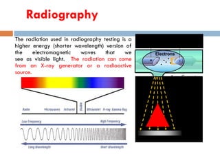
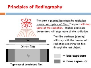
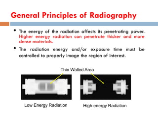
ME367 NON-DESTRUCTIVE TESTING
MODULE- 5 - RT
Sukesh O P, AP-ME , JECC16-Oct-18
SUKESH O P/ APME/JECC 1
ME357 Non-Destructive Testing
16-Oct-18SUKESH O P/ APME/JECC
2
Introduction to NDT- Visual Inspection- Liquid
Penetrant Inspection- Magnetic Particle
Inspection- Ultrasonic Testing-
Radiography Testing-
Eddy Current Testing.
MODULE-4
16-Oct-18SUKESH O P/ APME/JECC
3
Radiography
16-Oct-18SUKESH O P/ APME/JECC
4
 Radiography is an imaging technique using X-rays
to view the internal structure of an object.
 To create the image, a beam of X-rays, a form of
electromagnetic radiation, is produced by an X-ray
generator and is projected toward the object.
Radiography
The radiation used in radiography testing is a
higher energy (shorter wavelength) version of
the electromagnetic waves that we
see as visible light. The radiation can come
from an X-ray generator or a radioactive
source.
High Electrical Potential
Electrons
-+
X-ray Generator
or Radioactive
Source Creates
Radiation
Exposure Recording Device
Radiation
Penetrate
the Sample
Radiographic Testing (RT)
16-Oct-18SUKESH O P/ APME/JECC
6
 Industrial radiography is a method of non-
destructive testing where many types of manufactured
components can be examined to verify the internal
structure and integrity of the specimen.
Industrial Radiography can be performed utilizing
either X-rays or gamma rays. Both are forms of
electromagnetic radiation.
 Radiographic Testing (RT) – This method of
weld testing makes use of X-rays, produced by an X-
ray tube, or gamma rays, produced by a radioactive
isotope. The basic principle of radiographic inspection
of welds is the same as that for medical radiography.
Principles of Radiography
Top view of developed film
X-ray film
The part is placed between the radiation
source and a piece of film. The part will stop
some of the radiation. Thicker and more
dense area will stop more of the radiation.
= more exposure
= less exposure
The film darkness (density)
will vary with the amount of
radiation reaching the film
through the test object.
General Principles of Radiography
• The energy of the radiation affects its penetrating power.
Higher energy radiation can penetrate thicker and more
dense materials.
• The radiation energy and/or exposure time must be
controlled to properly image the region of interest.
Thin Walled Area
Low Energy Radiation High energy Radiation
Radiographic Images
Benefits of Radiographic Testing
16-Oct-18SUKESH O P/ APME/JECC
10
 Can inspect assembled components
 Minimum surface preparation required
 Detects both surface and subsurface defects
 Provides a permanent record of the inspection
 Verify internal flaws on complex structures
 Isolate and inspect internal components
 Automatically detect and measure internal flaws
 Measure dimensions and angles within the sample without
sectioning
 Sensitive to changes in thickness, corrosion, flaws and
material density changes
IDL 2001
Radiography has
sensitivity limitations
when detecting
cracks.
X-rays “see” a crack as a thickness variation and the larger the
variation, the easier the crack is to detect.
Optimum
Angle
Flaw Orientation
= easy to
detect
= not easy
to detect
When the path of the x-rays is not parallel to a crack, the thickness variation is
less and the crack may not be visible.
IDL 2001
0o 10o 20o
Since the angle between the radiation beam and a crack or other
linear defect is so critical, the orientation of defect must be well
known if radiography is going to be used to perform the
inspection.
Flaw Orientation (cont.)
Radiation Sources
Two of the most commonly used sources of radiation in
industrial radiography are x-ray generators and gamma ray
sources. Industrial radiography is often subdivided into “X-
ray Radiography” or “Gamma Radiography”, depending on
the source of radiation used.
Gamma Radiography
•Gamma rays are produced by
a radioisotope.
•A radioisotope has an
unstable nuclei that does not
have enough binding energy
to hold the nucleus together.
•The spontaneous breakdown
of an atomic nucleus resulting
in the release of energy and
matter is known as radioactive
decay.
Gamma Radiography (cont.)
•Most of the radioactive
material used in industrial
radiography is artificially
produced.
•This is done by subjecting
stable material to a source of
neutrons in a special nuclear
reactor. This process is called
activation.
Gamma Radiography (cont.)
Unlike X-rays, which are produced by
a machine, gamma rays cannot be
turned off. Radioisotopes used for
gamma radiography are
encapsulated to prevent leakage of
the material.
The radioactive “capsule” is
attached to a cable to form what is
often called a “pigtail.”
The pigtail has a special connector
at the other end that attaches to a
drive cable.
Gamma Radiography (cont.)
A device called a “camera” is used to store, transport and
expose the pigtail containing the radioactive material. The
camera contains shielding material which reduces the
radiographer’s exposure to radiation during use.
Gamma Radiography (cont.)
A hose-like device called
a guide tube is connected
to a threaded hole called
an “exit port” in the
camera.
The radioactive material
will leave and return to
the camera through this
opening when performing
an exposure!
Gamma Radiography (cont.)
A “drive cable” is connected to the
other end of the camera. This cable,
controlled by the radiographer, is
used to force the radioactive
material out into the guide tube
where the gamma rays will pass
through the specimen and expose
the recording device.
X-ray Radiography
Unlike gamma rays, x-rays are produced by an X-ray
generator system. These systems typically include an X-ray tube
head, a high voltage generator, and a control console.
X-ray Radiography (cont.)
• X-rays are produced by establishing a very high voltage
between two electrodes, called the anode and cathode.
• To prevent arcing, the anode and cathode are located inside
a vacuum tube, which is protected by a metal housing.
X-ray Radiography (cont.)
• The cathode contains a small filament
much the same as in a light bulb.
• Current is passed through the filament
which heats it. The heat causes
electrons to be stripped off.
• The high voltage causes these “free”
electrons to be pulled toward a target
material (usually made of tungsten)
located in the anode.
• The electrons impact against the
target. This impact causes an energy
exchange which causes x-rays to be
created.
High Electrical Potential
Electrons
-+
X-ray Generator
or Radioactive
Source Creates
Radiation
Exposure Recording Device
Radiation
Penetrate
the Sample
X ray source
16-Oct-18SUKESH O P/ APME/JECC
23
 The energy required for this process is provided from
the generator , which is connected to an electrical circuit
system. A rectifier is also provided in the electrical
system, to convert the electrical energy from the
generator into the direct current(DC), which is being the
adequate form to be applied to the X-ray tube.
 The quality and the quantity of the X-ray generation
are usually controlled by adjusting the electrical
parameters(such as voltage applied to the tube or
current flows through the tube) and exposure
time(usually a fraction of a second)
Production of x-rays
16-Oct-18SUKESH O P/ APME/JECC
24
 Normally X-rays, are produced when fast moving
electrons are suddenly brought to rest by colliding
with matter.
 During collision, the accelerated electrons therefore
lose their kinetic energy very rapidly at the surface
of the metal plate and energy conversion
consequently occurs. The kinetic energy of the
accelerated electrons ca be converted in 3 ways.
Production of x-rays
16-Oct-18SUKESH O P/ APME/JECC
25
1. A very small fraction I.E., less than 1% is converted
into X-radiation. The conversion factor f can be
estimated by an approximate empirical relation
f= 1.1×10⁻⁹ ZV
Where,
Z- atomic number of the target
V-energy of electron in volts
Production of x-rays
16-Oct-18SUKESH O P/ APME/JECC
26
2. Approx. 99% of energy of electrons is converted into
heat by increasing the thermal vibrations of the atoms
of the target, the temperature of which may
consequently rise considerably.
3. Some of electrons have sufficient energy to eject
orbital electrons from the atoms of the target material
which are ionized. The secondary electrons produced
in this way, may escape from the surface of the target
and subsequently be recaptured by it producing
further heat or secondary radiation.
High energy X-ray source or HEX
16-Oct-18SUKESH O P/ APME/JECC
27
 High energy X-ray source or HEX rays are very
hard X-rays whose energy value is 1 MeV or more,
which is about one order of magnititude higher than
convectional X-rays.
 This high energy X-rays are generally used when
examining thicker sections . Also, by using high
energy X-rays, the possibilities of large distance to
thickness ratios with correspondingly low
geometrical distortion, short production times and
high production rate can be achieved.
Benefits of HEX-rays
16-Oct-18SUKESH O P/ APME/JECC
28
 High energy X-ray source has small focal spot size
which reduces the amount of high angle scattered
X-rays reaching the film, thus resulting in
radiographswith good contrast.
 It has excellent penetrameter sensitivity and good
resolution.
Properties of X-Ray and Gamma ray
16-Oct-18SUKESH O P/ APME/JECC
29
 They are invisible and travels at the speed of the light.
 They propagate in a straight line and pass through
space without transference of matter,
 They are not affected by electric and magnetic fields.
 They are capable of ionizing gases and also changes
the electrical properties of solids and liquids.
 They are capable of blackening photographic film
 They exhibit wave properties and are reflected,
refracted, diffracted & polarized.

Radiographic Testing (RT)- NDT

  • 1.
    ME367 NON-DESTRUCTIVE TESTING MODULE-5 - RT Sukesh O P, AP-ME , JECC16-Oct-18 SUKESH O P/ APME/JECC 1
  • 2.
    ME357 Non-Destructive Testing 16-Oct-18SUKESHO P/ APME/JECC 2 Introduction to NDT- Visual Inspection- Liquid Penetrant Inspection- Magnetic Particle Inspection- Ultrasonic Testing- Radiography Testing- Eddy Current Testing.
  • 3.
  • 4.
    Radiography 16-Oct-18SUKESH O P/APME/JECC 4  Radiography is an imaging technique using X-rays to view the internal structure of an object.  To create the image, a beam of X-rays, a form of electromagnetic radiation, is produced by an X-ray generator and is projected toward the object.
  • 5.
    Radiography The radiation usedin radiography testing is a higher energy (shorter wavelength) version of the electromagnetic waves that we see as visible light. The radiation can come from an X-ray generator or a radioactive source. High Electrical Potential Electrons -+ X-ray Generator or Radioactive Source Creates Radiation Exposure Recording Device Radiation Penetrate the Sample
  • 6.
    Radiographic Testing (RT) 16-Oct-18SUKESHO P/ APME/JECC 6  Industrial radiography is a method of non- destructive testing where many types of manufactured components can be examined to verify the internal structure and integrity of the specimen. Industrial Radiography can be performed utilizing either X-rays or gamma rays. Both are forms of electromagnetic radiation.  Radiographic Testing (RT) – This method of weld testing makes use of X-rays, produced by an X- ray tube, or gamma rays, produced by a radioactive isotope. The basic principle of radiographic inspection of welds is the same as that for medical radiography.
  • 7.
    Principles of Radiography Topview of developed film X-ray film The part is placed between the radiation source and a piece of film. The part will stop some of the radiation. Thicker and more dense area will stop more of the radiation. = more exposure = less exposure The film darkness (density) will vary with the amount of radiation reaching the film through the test object.
  • 8.
    General Principles ofRadiography • The energy of the radiation affects its penetrating power. Higher energy radiation can penetrate thicker and more dense materials. • The radiation energy and/or exposure time must be controlled to properly image the region of interest. Thin Walled Area Low Energy Radiation High energy Radiation
  • 9.
  • 10.
    Benefits of RadiographicTesting 16-Oct-18SUKESH O P/ APME/JECC 10  Can inspect assembled components  Minimum surface preparation required  Detects both surface and subsurface defects  Provides a permanent record of the inspection  Verify internal flaws on complex structures  Isolate and inspect internal components  Automatically detect and measure internal flaws  Measure dimensions and angles within the sample without sectioning  Sensitive to changes in thickness, corrosion, flaws and material density changes
  • 11.
    IDL 2001 Radiography has sensitivitylimitations when detecting cracks. X-rays “see” a crack as a thickness variation and the larger the variation, the easier the crack is to detect. Optimum Angle Flaw Orientation = easy to detect = not easy to detect When the path of the x-rays is not parallel to a crack, the thickness variation is less and the crack may not be visible.
  • 12.
    IDL 2001 0o 10o20o Since the angle between the radiation beam and a crack or other linear defect is so critical, the orientation of defect must be well known if radiography is going to be used to perform the inspection. Flaw Orientation (cont.)
  • 13.
    Radiation Sources Two ofthe most commonly used sources of radiation in industrial radiography are x-ray generators and gamma ray sources. Industrial radiography is often subdivided into “X- ray Radiography” or “Gamma Radiography”, depending on the source of radiation used.
  • 14.
    Gamma Radiography •Gamma raysare produced by a radioisotope. •A radioisotope has an unstable nuclei that does not have enough binding energy to hold the nucleus together. •The spontaneous breakdown of an atomic nucleus resulting in the release of energy and matter is known as radioactive decay.
  • 15.
    Gamma Radiography (cont.) •Mostof the radioactive material used in industrial radiography is artificially produced. •This is done by subjecting stable material to a source of neutrons in a special nuclear reactor. This process is called activation.
  • 16.
    Gamma Radiography (cont.) UnlikeX-rays, which are produced by a machine, gamma rays cannot be turned off. Radioisotopes used for gamma radiography are encapsulated to prevent leakage of the material. The radioactive “capsule” is attached to a cable to form what is often called a “pigtail.” The pigtail has a special connector at the other end that attaches to a drive cable.
  • 17.
    Gamma Radiography (cont.) Adevice called a “camera” is used to store, transport and expose the pigtail containing the radioactive material. The camera contains shielding material which reduces the radiographer’s exposure to radiation during use.
  • 18.
    Gamma Radiography (cont.) Ahose-like device called a guide tube is connected to a threaded hole called an “exit port” in the camera. The radioactive material will leave and return to the camera through this opening when performing an exposure!
  • 19.
    Gamma Radiography (cont.) A“drive cable” is connected to the other end of the camera. This cable, controlled by the radiographer, is used to force the radioactive material out into the guide tube where the gamma rays will pass through the specimen and expose the recording device.
  • 20.
    X-ray Radiography Unlike gammarays, x-rays are produced by an X-ray generator system. These systems typically include an X-ray tube head, a high voltage generator, and a control console.
  • 21.
    X-ray Radiography (cont.) •X-rays are produced by establishing a very high voltage between two electrodes, called the anode and cathode. • To prevent arcing, the anode and cathode are located inside a vacuum tube, which is protected by a metal housing.
  • 22.
    X-ray Radiography (cont.) •The cathode contains a small filament much the same as in a light bulb. • Current is passed through the filament which heats it. The heat causes electrons to be stripped off. • The high voltage causes these “free” electrons to be pulled toward a target material (usually made of tungsten) located in the anode. • The electrons impact against the target. This impact causes an energy exchange which causes x-rays to be created. High Electrical Potential Electrons -+ X-ray Generator or Radioactive Source Creates Radiation Exposure Recording Device Radiation Penetrate the Sample
  • 23.
    X ray source 16-Oct-18SUKESHO P/ APME/JECC 23  The energy required for this process is provided from the generator , which is connected to an electrical circuit system. A rectifier is also provided in the electrical system, to convert the electrical energy from the generator into the direct current(DC), which is being the adequate form to be applied to the X-ray tube.  The quality and the quantity of the X-ray generation are usually controlled by adjusting the electrical parameters(such as voltage applied to the tube or current flows through the tube) and exposure time(usually a fraction of a second)
  • 24.
    Production of x-rays 16-Oct-18SUKESHO P/ APME/JECC 24  Normally X-rays, are produced when fast moving electrons are suddenly brought to rest by colliding with matter.  During collision, the accelerated electrons therefore lose their kinetic energy very rapidly at the surface of the metal plate and energy conversion consequently occurs. The kinetic energy of the accelerated electrons ca be converted in 3 ways.
  • 25.
    Production of x-rays 16-Oct-18SUKESHO P/ APME/JECC 25 1. A very small fraction I.E., less than 1% is converted into X-radiation. The conversion factor f can be estimated by an approximate empirical relation f= 1.1×10⁻⁹ ZV Where, Z- atomic number of the target V-energy of electron in volts
  • 26.
    Production of x-rays 16-Oct-18SUKESHO P/ APME/JECC 26 2. Approx. 99% of energy of electrons is converted into heat by increasing the thermal vibrations of the atoms of the target, the temperature of which may consequently rise considerably. 3. Some of electrons have sufficient energy to eject orbital electrons from the atoms of the target material which are ionized. The secondary electrons produced in this way, may escape from the surface of the target and subsequently be recaptured by it producing further heat or secondary radiation.
  • 27.
    High energy X-raysource or HEX 16-Oct-18SUKESH O P/ APME/JECC 27  High energy X-ray source or HEX rays are very hard X-rays whose energy value is 1 MeV or more, which is about one order of magnititude higher than convectional X-rays.  This high energy X-rays are generally used when examining thicker sections . Also, by using high energy X-rays, the possibilities of large distance to thickness ratios with correspondingly low geometrical distortion, short production times and high production rate can be achieved.
  • 28.
    Benefits of HEX-rays 16-Oct-18SUKESHO P/ APME/JECC 28  High energy X-ray source has small focal spot size which reduces the amount of high angle scattered X-rays reaching the film, thus resulting in radiographswith good contrast.  It has excellent penetrameter sensitivity and good resolution.
  • 29.
    Properties of X-Rayand Gamma ray 16-Oct-18SUKESH O P/ APME/JECC 29  They are invisible and travels at the speed of the light.  They propagate in a straight line and pass through space without transference of matter,  They are not affected by electric and magnetic fields.  They are capable of ionizing gases and also changes the electrical properties of solids and liquids.  They are capable of blackening photographic film  They exhibit wave properties and are reflected, refracted, diffracted & polarized.