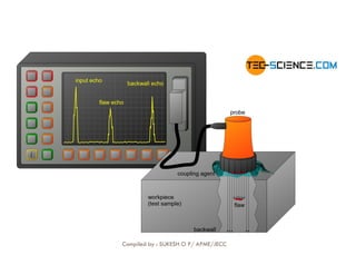
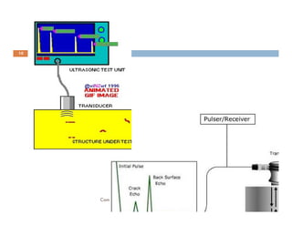
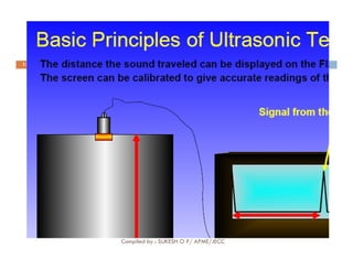
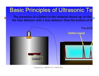
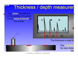
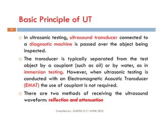
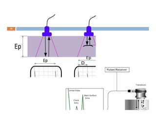
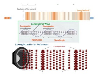
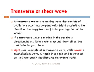
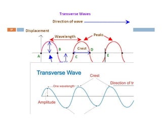
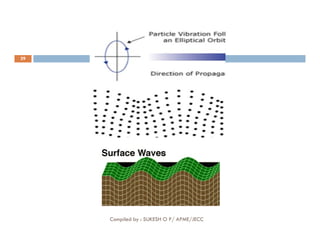
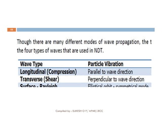
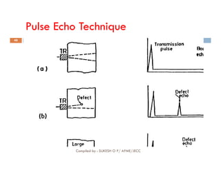
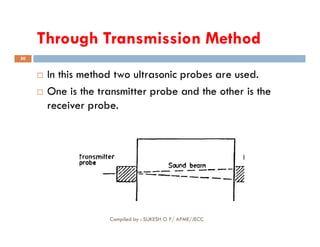
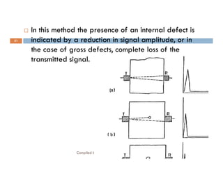
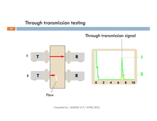
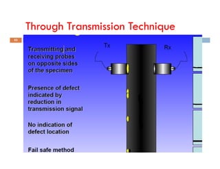
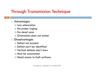
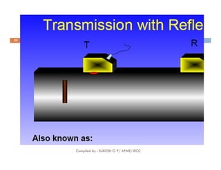
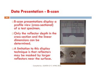
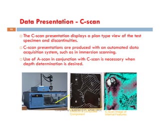
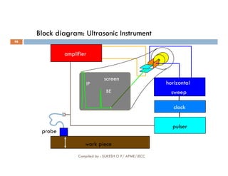
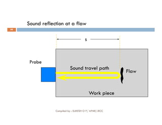
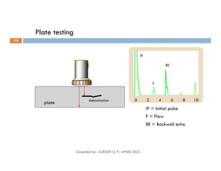
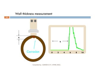
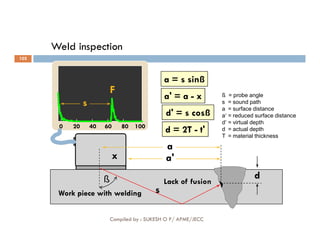
MET312 NON
MET312 NON-
-DESTRUCTIVE TESTING
DESTRUCTIVE TESTING
MODULE
MODULE-
-4
4 –
– ULTRASONIC TESTING
ULTRASONIC TESTING
Compiled by : SUKESH O P/ APME/JECC 1
MODULE
MODULE-
-4
4 –
– ULTRASONIC TESTING
ULTRASONIC TESTING
Sukesh O P
Assistant Professor
Department of Mechanical Engineering,
Jyothi Engineering College, Cheruthuruthy
9633103837 II sukeshop@jecc.ac.in
ME357 Non-Destructive Testing
2
Introduction to NDT
Introduction to NDT-
- Visual Inspection
Visual Inspection-
- Liquid
Liquid
Penetrant Inspection
Penetrant Inspection-
- Magnetic
Magnetic Particle
Particle
Inspection
Inspection-
- Ultrasonic Testing
Ultrasonic Testing-
-
Compiled by : SUKESH O P/ APME/JECC
Inspection
Inspection-
- Ultrasonic Testing
Ultrasonic Testing-
-
Radiography Testing
Radiography Testing-
- Eddy Current Testing.
Eddy Current Testing.
Module-4 Syllabus
3
 Ultrasonic Testing: Basic principles of sound propagation,
types of sound waves, Principle of UT-methods of UT, their
advantages and limitations- Piezoelectric Material, Various
types of transducers/probe-Calibration methods, contact
testing and immersion testing, normal beam and straight
beam testing, angle beam testing, dual crystal probe,
ultrasonic testing techniques resonance testing, through
Compiled by : SUKESH O P/ APME/JECC
ultrasonic testing techniques resonance testing, through
transmission technique, pulse echo testing technique,
instruments used UT, accessories such as transducers, types,
frequencies, and sizes commonly used. Reference of standard
blocks-technique for normal beam inspection-flaw
characterization technique, defects in welded products by UT-
Thickness determination by ultrasonic method;- Study of A, B
and C scan presentations-Time of Flight Diffraction (TOFD)
MODULE
MODULE-
-4
4
4
Compiled by : SUKESH O P/ APME/JECC
5
Compiled by : SUKESH O P/ APME/JECC
6
 The three types of sound are:

 Infrasonic
Infrasonic:
: It is a sound with a frequency of less than
20Hz. Elephants use Infrasonic sounds to interact
with herds hundreds of km away.
Compiled by : SUKESH O P/ APME/JECC
with herds hundreds of km away.

 Sonic
Sonic:
: It is a sound with the frequency between 20
to 20,000Hz. ...

 Ultrasonic
Ultrasonic:
: It is a sound with a frequency more than
20,000Hz.
Infrasonic sound
7
 Having or relating to a frequency below the
audibility range of the human ear.
 utilizing or produced by infrasonic waves or
vibrations.
Compiled by : SUKESH O P/ APME/JECC
vibrations.
 Infrasound, is a low-frequency sound less than
20Hz. Animals that can communicate using infrasonic
sounds are; Rhinos, hippos, elephants, whales,
octopus, pigeons, squid, cuttlefish, cod, Guinea
fowl.
Ultrasonic sound
8
 The definition of ultrasonic, also known as
ultrasound, is sound waves that have a higher
frequency than the human ear can hear. An
example of ultrasonic is an ultrasound image of an
unborn baby.
Compiled by : SUKESH O P/ APME/JECC
unborn baby.
 Bats, Insects like beetles, moths, praying mantis,
dolphins, dogs, frogs and toads, etc. communicate
using ultrasonic hearing.
9
Compiled by : SUKESH O P/ APME/JECC
10
Compiled by : SUKESH O P/ APME/JECC
INTRODUCTION
INTRODUCTION
11
 Ultrasonic testing(UT) which is applicable to most
materials, metallic or non-metallic.
 Ultrasonic testing uses high frequency sound energy to
conduct examinations and make measurements.
 Ultrasonic examinations can be conducted on a wide
Frequencies from 1-10 Mega Hertz(MHz)
are typically used.
Compiled by : SUKESH O P/ APME/JECC
 Ultrasonic examinations can be conducted on a wide
variety of material forms including castings, forgings,
welds, and composites.
 By this method, surface and internal discontinuities such
as laps, seams, voids, cracks, blow holes, inclusions and
lack of bond can be accurately evaluated from one
side.
12
Compiled by : SUKESH O P/ APME/JECC
13
Compiled by : SUKESH O P/ APME/JECC
14
Compiled by : SUKESH O P/ APME/JECC
15
Compiled by : SUKESH O P/ APME/JECC
16
Compiled by : SUKESH O P/ APME/JECC
Basic Principle of UT
17
 In ultrasonic testing, ultrasound transducer connected to
a diagnostic machine is passed over the object being
inspected.
 The transducer is typically separated from the test
object by a couplant (such as oil) or by water, as in
Compiled by : SUKESH O P/ APME/JECC
object by a couplant (such as oil) or by water, as in
immersion testing. However, when ultrasonic testing is
conducted with an Electromagnetic Acoustic Transducer
(EMAT) the use of couplant is not required.
 There are two methods of receiving the ultrasound
waveform: reflection and attenuation
18
Compiled by : SUKESH O P/ APME/JECC
SOUND
19
Wavelength :
 The distance required to complete a cycle
– Measured in Meter or mm
Frequency :
The number of cycles per unit time
Compiled by : SUKESH O P/ APME/JECC
 The number of cycles per unit time
– Measured in Hertz (Hz) or Cycles per second (cps)
Velocity :
 How quick the sound travels
 Distance per unit time
– Measured in meter / second (m / sec)
Basic Principles of Sound
Sound is produced by a vibrating body and travels in the form
of a wave.
Sound waves travel through materials by vibrating the
particles that make up the material.
The pitch of the sound
is determined by the
frequency of the wave
(vibrations or cycles
completed in a certain
period of time).
Ultrasound is sound
with a pitch too high
to be detected by the
human ear.
Compiled by : SUKESH O P/
APME/JECC
20
Properties of a sound wave
21
 Sound cannot travel in vacuum
 Sound energy to be transmitted / transferred from
one particle to another
Compiled by : SUKESH O P/ APME/JECC
Sound waves
22
 All sound waves, whether audible or ultrasonic, are
mechanical vibrations involving movement of the
medium in which they are travelling.
 A sound wave may be transmitted through any
Compiled by : SUKESH O P/ APME/JECC
 A sound wave may be transmitted through any
material which behaves in an elastic manner.
 Longitudinal waves
 Transverse or shear waves
 Surface or Rayleigh waves
Ultrasonic waves
 Ultrasonic waves are very similar to light waves
in that they can be reflected, refracted, and
focused.
 Reflection and refraction occurs when sound
waves interact with interfaces of differing
acoustic properties.
 In solid materials, the vibrational energy can be
split into different wave modes when the wave
encounters an interface at an angle other than
90 degrees.
 Ultrasonic reflections from the presence of
discontinuities or geometric features enables
detection and location.
 The velocity of sound in a given material is
constant and can only be altered by a change in
the mode of energy. Compiled by : SUKESH O P/
APME/JECC
23
Longitudinal waves
24
 Longitudinal waves are waves in which the
displacement of the medium is in the same direction
as, or the opposite direction to, the direction of
propagation of the wave.
Mechanical longitudinal waves are also
Compiled by : SUKESH O P/ APME/JECC
 Mechanical longitudinal waves are also
called compressional or compression waves, because
they produce compression and rarefaction when
traveling through a medium, and pressure waves,
because they produce increases and decreases in
pressure.
25
Compiled by : SUKESH O P/ APME/JECC
Transverse or shear wave
26
 A transverse wave is a moving wave that consists of
oscillations occurring perpendicular (right angled) to the
direction of energy transfer (or the propagation of the
wave).
If a transverse wave is moving in the positive x-
Compiled by : SUKESH O P/ APME/JECC
 If a transverse wave is moving in the positive x-
direction, its oscillations are in up and down directions
that lie in the y–z plane.
 Light is an example of a transverse wave, while sound is
a longitudinal wave. A ripple in a pond and a wave on
a string are easily visualized as transverse waves.
27
Compiled by : SUKESH O P/ APME/JECC
Surface or Rayleigh waves
28
 This type of waves can travel only along surface
bounded on one side by strong elastic forces of the
solid and on the other by nearly nonexistent elastic
forces between gas molecules.
Compiled by : SUKESH O P/ APME/JECC
 Surface waves therefore are essentially nonexistent
in a solid immersed in liquid, unless the liquid covers
the solid surface only as a very thin layer.
29
Compiled by : SUKESH O P/ APME/JECC
Plate or Lamp waves
30
Compiled by : SUKESH O P/ APME/JECC
31
Compiled by : SUKESH O P/ APME/JECC
32
Compiled by : SUKESH O P/ APME/JECC
VELOCITY
33
 The velocity of sound in a particular material is CONSTANT
 It is the product of DENSITY and ELASTICITY of the material
 It will NOT change if frequency changes
 Only the wavelength changes
 Examples:
Compiled by : SUKESH O P/ APME/JECC
 Examples:
 V Compression in steel : 5960 m/s
 V Compression in water : 1470 m/s
 V Compression in air : 330 m/s
34
Compiled by : SUKESH O P/ APME/JECC
35
Compiled by : SUKESH O P/ APME/JECC
36
Compiled by : SUKESH O P/ APME/JECC
37
Compiled by : SUKESH O P/ APME/JECC
FREQUENCY
38
 Generally the choice of test frequency depends
upon two factors : the
the minimum
minimum size
size of
of defect,
defect, which
which
is
is to
to be
be detected
detected and
and the
the medium
medium in
in which
which such
such a
a
defect
defect is
is situated
situated.
.
Compiled by : SUKESH O P/ APME/JECC
39
Compiled by : SUKESH O P/ APME/JECC
40
Compiled by : SUKESH O P/ APME/JECC
41
Compiled by : SUKESH O P/ APME/JECC
Reflection
42
 Light can bend and move through the material,
which is called refraction. Or, light can bounce off
the material, which is called reflection.
 When sound travels in a given medium, it strikes the
Compiled by : SUKESH O P/ APME/JECC
 When sound travels in a given medium, it strikes the
surface of another medium and bounces back in
some other direction, this phenomenon
is called the reflection of sound. The waves
are called the incident and reflected sound waves.
Divergence
43
 A term used to describe the spreading of ultrasonic
waves beyond the near field. It is a function of the
transducer diameter and wave length in the
medium.
Compiled by : SUKESH O P/ APME/JECC
 Divergence angle, angle within the far field between
the beam axis and the beam edge at which the
amplitude has fallen by a defined level
44
 Scattering : it is the reflection of sound beam from
its original direction of propagation.
 Absorption : it is conversion of sound energy from
one form to some another form.
Compiled by : SUKESH O P/ APME/JECC
one form to some another form.
Attenuation of sound waves
45
 It is a combined effect of scattering and absorption.
Which states that when a sound beam travels
through any medium, its intensity gradually reduces
due to scattering and absorption.
Compiled by : SUKESH O P/ APME/JECC
 Attenaution defines the decay rate of propagated
sound wave.
TEST TECHNIQUES
TEST TECHNIQUES
46
 Ultrasonic testing is a very versatile inspection method, and
inspections can be accomplished in a number of different ways.
 Ultrasonic inspection techniques are commonly divided into three
primary classifications.
Pulse-echo and Through Transmission
Compiled by : SUKESH O P/ APME/JECC
 Pulse-echo and Through Transmission
- (Relates to whether reflected or transmitted energy is used)
 Normal Beam and Angle Beam
- (Relates to the angle that the sound energy enters the test article)
 Contact and Immersion
- (Relates to the method of coupling the transducer to the test article)
Pulse
Pulse Echo
Echo Method
Method
47
 This is the method most commonly utilized in the
ultrasonic testing of materials. The transmitter and
receiver probes are on the same side of the specimen
and the presence of a defect is indicated by the
reception of an echo before that of the back wall echo.
Compiled by : SUKESH O P/ APME/JECC
reception of an echo before that of the back wall echo.
 The CRT screen is calibrated to show the separation in
distance between the time of arrival of a defect echo
as against that of the back wall echo of the specimen,
therefore, the location of a defect can be assessed
accurately.
Pulse Echo Technique
48
Compiled by : SUKESH O P/ APME/JECC
Pulse Echo Technique
49
 Single probe sends and receives sound
 Gives an indication of defect depth and dimensions
 Not fail safe
Compiled by : SUKESH O P/ APME/JECC
Through Transmission Method
50
 In this method two ultrasonic probes are used.
 One is the transmitter probe and the other is the
receiver probe.
Compiled by : SUKESH O P/ APME/JECC
51
 In this method the presence of an internal defect is
indicated by a reduction in signal amplitude, or in
the case of gross defects, complete loss of the
transmitted signal.
Compiled by : SUKESH O P/ APME/JECC
Through transmission testing
Through transmission signal
1 1
T R
52
0 2 4 6 8 10
2 2
T R
Flaw
Compiled by : SUKESH O P/ APME/JECC
Through Transmission Technique
53
Compiled by : SUKESH O P/ APME/JECC
Through Transmission Technique
54
 Advantages
 Less attenuation
 No probe ringing
 No dead zone
 Orientation does not matter
Compiled by : SUKESH O P/ APME/JECC
Orientation does not matter
 Disadvantages
 Defect not located
 Defect can’t be identified
 Vertical defects don’t show
 Must be automated
 Need access to both surfaces
55
Compiled by : SUKESH O P/ APME/JECC
Resonance Method
Resonance Method
56
 A condition of resonance exists whenever the
thickness of a material equals half the wavelength
of sound or any multiple thereof in that material.
 Control of wavelength in ultrasonics is achieved by
Compiled by : SUKESH O P/ APME/JECC
 Control of wavelength in ultrasonics is achieved by
control of frequency.
Resonance Method
57
 Knowing the resonance or fundamental frequency f
and velocity V of ultrasound in the specimen the
thickness ‘t’ of the specimen under test can be
calculated from the equation : -
Compiled by : SUKESH O P/ APME/JECC
 Since it is difficult to recognize the fundamental
mode of vibration, the fundamental frequency is
usually calculated from the difference of two
adjacent harmonics which are depicted by two
adjacent rises in the pulse amplitude.
Resonance Method
58
 This method is used for the inspection of large ingots
and castings particularly when the attenuation is
high and gross defects are present.
 The method does
does not
not give
give the
the size
size and
and location
location of
of
Compiled by : SUKESH O P/ APME/JECC
 The method does
does not
not give
give the
the size
size and
and location
location of
of
the
the defect
defect.
. In addition good mechanical coupling
and alignment of the two probes is essential.
59
 Techniques of ultrasonic testing are either of the
contact type or the immersion type.

 In
In the
the contact
contact type
type, the probe is placed in direct
contact with the test specimen with a thin liquid film
used as a couplant for better transmission of
Compiled by : SUKESH O P/ APME/JECC
used as a couplant for better transmission of
ultrasonic waves in to the test specimen.

 In
In the
the immersion
immersion type
type, a waterproof probe is used
at some distance from the test specimen and the
ultrasonic beam is transmitted in to the material
through a water path or water column.
Contact Type Techniques
60
Normal
Normal Beam
Beam Techniques
Techniques:
:
 In the normal beam technique the ultrasonic beam is
projected perpendicularly in to the test specimen. This
technique may use either single, double or SE normal
beam probes.
Compiled by : SUKESH O P/ APME/JECC
beam probes.
 With the single probe, the transducer of the probe acts
as both transmitter and receiver.
 In this technique an ultrasonic beam pulse is projected
at in to the specimen and echoes from the flaws within
the specimen and from the back wall of the specimen
are received.
Straight beam inspection techniques:
Direct contact,
single element probe
Direct contact,
dual element probe
Fixed delay
61
Immersion testing
Through transmission
Compiled by : SUKESH O P/ APME/JECC
62

 Angle
Angle Beam
Beam Techniques
Techniques
 The angle beam technique is used to transmit ultrasonic
waves in to a test specimen at a predetermined
predetermined angle
angle
to
to the
the test
test surface
surface.
.
 According to the angle selected, the wave modes
produced in the test specimen may be mixed
Compiled by : SUKESH O P/ APME/JECC
 According to the angle selected, the wave modes
produced in the test specimen may be mixed
longitudinal and transverse, transverse only, or surface
wave modes.

 Transverse
Transverse waves
waves at various angles of refraction
between 35
35°
° and
and 80
80°
° are used to locate defects whose
orientation is not suitable for detection by normal beam
techniques.
63

 Surface
Surface Wave
Wave Techniques
Techniques
 Surface wave techniques have been used very successfully
for a great number of applications, particularly in the
Aircraft Industry.
 The main advantage of surface waves is that they follow
gentle contours and are reflected sharply only by sudden
Compiled by : SUKESH O P/ APME/JECC
gentle contours and are reflected sharply only by sudden
changes in contour, thus making it a very useful tool for the
examination of complex shaped components.
 The main limitation of these waves is that they are almost
immediately attenuated if the surface finish is rough, is
covered in scale or a liquid (such as the couplant), or if any
pressure is applied by another object (such as the hand of
the operator ).
Immersion Testing Techniques
64
 Immersion testing techniques are mainly used in the
laboratory
laboratory and
and for
for large
large installations
installations doing
doing automatic
automatic
ultrasonic
ultrasonic testing
testing.
. It has the advantage that uniform
couplant conditions are obtained and longitudinal and
transverse waves can be generated with the same
probe simply by changing the incident beam angle.
Compiled by : SUKESH O P/ APME/JECC
probe simply by changing the incident beam angle.
 In the immersion technique both the probe and the test
specimen are immersed in water. The ultrasonic beam is
directed through the water in to the test specimen, using
either a normal beam technique for generating
longitudinal waves or an angle beam technique for
generating transverse waves.
surface =
sound entry
backwall flaw
1 2
water delay
Immersion testing
65
0 2 4 6 8 10 0 2 4 6 8 10
IE IE
IP IP
BE BE
F
1 2
Compiled by : SUKESH O P/ APME/JECC
66
Compiled by : SUKESH O P/ APME/JECC
Immersion testing
67
 In the bubbler or squirter technique, the ultrasonic beam
is directed through a water column in to the test
specimen.

 This
This technique
technique is
is usually
usually used
used with
with an
an automated
automated system
system
for
for high
high speed
speed scanning
scanning of
of plate,
plate, sheet,
sheet, strip
strip,
, cylindrical
cylindrical
Compiled by : SUKESH O P/ APME/JECC
for
for high
high speed
speed scanning
scanning of
of plate,
plate, sheet,
sheet, strip
strip,
, cylindrical
cylindrical
forms
forms and
and other
other regularly
regularly shaped
shaped forms
forms.
.
 The ultrasonic beam is either directed in a
perpendicular direction (i.e. normal direction ) to the
test specimen to produce longitudinal waves or is
adjusted at an angle to the surface of the test specimen
for the production of transverse waves.
Immersion testing
68
Compiled by : SUKESH O P/ APME/JECC
Immersion testing
69
 In the wheel transducer technique the ultrasonic
beam is projected through a water-filled tire in to
the test specimen.
 The probe, mounted on the wheel axle, is held in a
Compiled by : SUKESH O P/ APME/JECC
 The probe, mounted on the wheel axle, is held in a
fixed position while the wheel and tire rotate freely.
 The wheel may be mounted on a mobile apparatus
that runs across the specimen, or it may be mounted
on a stationary fixture, where the specimen is
moved past it
70
Compiled by : SUKESH O P/ APME/JECC
Equipment
Equipment
Equipment for ultrasonic testing is very diversified.
Proper selection is important to insure accurate
inspection data as desired for specific applications.
In general, there are three basic components that
comprise an ultrasonic test system:
71
comprise an ultrasonic test system:
- Instrumentation
- Transducers
- Calibration Standards
Compiled by : SUKESH O P/ APME/JECC
1. TRANSDUCERS
• Transducers are manufactured in a variety of forms,
shapes and sizes for varying applications.
• Transducers are categorized in a number of ways which
include:
- Contact or immersion
72
- Contact or immersion
- Single or dual element
- Normal or angle beam
• In selecting a transducer
for a given application, it
is important to choose the
desired frequency,
bandwidth, size, and in some cases focusing
which optimizes the inspection capabilities.
Compiled by : SUKESH O P/ APME/JECC
Contact Transducers
Contact transducers are
designed to withstand
rigorous use, and usually have
a wear plate on the bottom
surface to protect the
piezoelectric element from
contact with the surface of the
piezoelectric element from
contact with the surface of the
test article.
Many incorporate ergonomic
designs for ease of grip while
scanning along the surface.
Compiled by : SUKESH O P/
APME/JECC
73
Contact Transducers (cont.)
 Contact transducers are available with
two piezoelectric crystals in one
housing. These transducers are called
dual element transducers.
 One crystal acts as a transmitter, the
other as a receiver.
 This arrangement improves near surface
resolution because the second
transducer does not need to complete a
transmit function before listening for
echoes.
 Dual elements are commonly employed
in thickness gauging of thin materials.
Compiled by : SUKESH O P/
APME/JECC
74
Contact Transducers (cont.)
 A way to improve near surface
resolution with a single element
transducer is through the use of a delay
line.
 Delay line transducers have a plastic
piece that is a sound path that provides
a time delay between the sound
generation and reception of reflected
energy.
 Interchangeable pieces make it
possible to configure the transducer
with insulating wear caps or flexible
membranes that conform to rough
surfaces.
 Common applications include thickness
gauging and high temperature
measurements.
Compiled by : SUKESH O P/
APME/JECC
75
Angle beam Transducers
 Angle beam transducers
incorporate wedges to introduce
a refracted shear wave into a
material.
 The incident wedge angle is used
with the material velocity to
determine the desired refracted
shear wave according to Snell’s
Law)
 Transducers can use fixed or
variable wedge angles.
 Common application is in weld
examination.
Compiled by : SUKESH O P/
APME/JECC
76
Immersion Transducers
Immersion transducers are
designed to transmit sound
whereby the transducer and test
specimen are immersed in a liquid
coupling medium (usually water).
 Immersion transducers are
manufactured with planar,
cylindrical or spherical acoustic
lenses (focusing lens).
Compiled by : SUKESH O P/
APME/JECC
77
78
Compiled by : SUKESH O P/
APME/JECC
79
Compiled by : SUKESH O P/
APME/JECC
2. INSTRUMENTATION
 Ultrasonic equipment is usually purchased to satisfy
specific inspection needs, some users may purchase
general purpose equipment to fulfill a number of
inspection applications.
 Test equipment can be classified in a number of
80
 Test equipment can be classified in a number of
different ways, this may include portable or stationary,
contact or immersion, manual or automated.
 Further classification of instruments commonly divides
them into four general categories: D-meters, Flaw
detectors, Industrial and special application.
Compiled by : SUKESH O P/ APME/JECC
D-meters or digital thickness gauge
 D-meters or digital thickness
gauge instruments provide
the user with a digital
(numeric) readout.
 They are designed primarily
for corrosion/erosion
inspection applications.
• Some instruments provide the user with both a digital
readout and a display of the signal. A distinct advantage
of these units is that they allow the user to evaluate the
signal to ensure that the digital measurements are of the
desired features.
Compiled by : SUKESH O P/
APME/JECC
81
Flaw detectors
 Flaw detectors are instruments
designed primarily for the
inspection of components for
defects.
 However, the signal can be
evaluated to obtain other
information such as material
thickness values.
 Both analog and digital display.
 Offer the user options of gating
horizontal sweep and amplitude
threshold.
Compiled by : SUKESH O P/
APME/JECC
82
Industrial flaw detection instruments
 Industrial flaw detection
instruments, provide users with
more options than standard
flaw detectors.
 May be modulated units
allowing users to tailor the
instrument for their specific
needs.
 Generally not as portable as
standard flaw detectors.
Compiled by : SUKESH O P/
APME/JECC
83
Immersion ultrasonic scanning systems
 Immersion ultrasonic scanning systems
are used for automated data
acquisition and imaging.
 They integrate an immersion tank,
ultrasonic instrumentation, a scanning
bridge, and computer controls.
 The signal strength and/or the time-
of-flight of the signal is measured for
every point in the scan plan.
 The value of the data is plotted using
colors or shades of gray to produce
detailed images of the surface or
internal features of a component.
Compiled by : SUKESH O P/
APME/JECC
84
Images of a Quarter Produced With an Ultrasonic
Immersion Scanning System
85
Gray scale image produced using
the sound reflected from the front
surface of the coin
Gray scale image produced using the
sound reflected from the back surface
of the coin (inspected from “heads” side)
Compiled by : SUKESH O P/ APME/JECC
3. CALIBRATION STANDARDS
 Calibration is a operation of configuring the ultrasonic test
equipment to known values. This provides the inspector with
a means of comparing test signals to known measurements.
 Calibration standards come in a wide variety of material
types, and configurations due to the diversity of inspection
86
types, and configurations due to the diversity of inspection
applications.
 Calibration standards are typically manufactured from
materials of the same acoustic properties as those of the
test articles.
Compiled by : SUKESH O P/ APME/JECC
Calibration Standards (cont.)
Thickness calibration
standards may be flat or
curved for pipe and tubing
applications, consisting of
simple variations in material
thickness.
ASTM Distance/Area Amplitude
87
thickness.
Distance/Area Amplitude
standards utilize flat bottom
holes or side drilled holes to
establish known reflector size
with changes in sound path
form the entry surface.
NAVSHIPS
Compiled by : SUKESH O P/ APME/JECC
Calibration Standards (cont.)
There are also calibration
standards for use in angle
beam inspections when
flaws are not parallel to
entry surface.
IIW
DSC DC Rhompas
88
These standards utilized
side drilled holes, notches,
and geometric
configuration to establish
time distance and
amplitude relationships.
SC
ASME Pipe Sec. XI
Compiled by : SUKESH O P/ APME/JECC
Qualification Standards
Qualification standards
differ from calibration
standards in that their
use is for purposes of
varying proper
equipment operation
AWS Resolution DC-dB Accuracy
89
equipment operation
and qualification of
equipment use for
specific codes and
standards.
IOW Beam Profile
Compiled by : SUKESH O P/ APME/JECC
90
Compiled by : SUKESH O P/ APME/JECC
91
Compiled by : SUKESH O P/ APME/JECC
DATA PRESENTATION
 Information from ultrasonic testing can be presented in a
number of differing formats.
 Three of the more common formats include:
 A-scan
B-scan
92
 B-scan
 C-scan
Compiled by : SUKESH O P/ APME/JECC
Data Presentation - A-scan

 A
A-
-scan presentation displays
scan presentation displays
the amount of received
ultrasonic energy as a function
of time.
of time.
 Relative discontinuity size can
be estimated by comparing
Signal
Amplitude
be estimated by comparing
the signal amplitude to that
from a known reflector.
 Reflector depth can be
determined by the position of
the signal on the horizontal
sweep.
Time
Signal
Amplitude
Time
Compiled by : SUKESH O P/
APME/JECC
93
Data Presentation - B-scan

B
B-
-scan presentations display a
scan presentations display a
profile view (cross
profile view (cross-
-sectional)
sectional)
of a test specimen.
of a test specimen.
Only the reflector depth in the
cross-section and the linear
94
cross-section and the linear
dimensions can be
determined.
A limitation to this display
technique is that reflectors
may be masked by larger
reflectors near the surface.
Compiled by : SUKESH O P/ APME/JECC
Data Presentation - C-scan

 The C
The C-
-scan presentation displays a plan type view of the test
scan presentation displays a plan type view of the test
specimen and discontinuities.
 C-scan presentations are produced with an automated data
acquisition system, such as in immersion scanning.
 Use of A-scan in conjunction with C-scan is necessary when
depth determination is desired.
95
depth determination is desired.
Photo of a Composite
Component
C-Scan Image of
Internal Features
Compiled by : SUKESH O P/ APME/JECC
ADVANTAGE OF ULTRASONIC TESTING
 Sensitive to small discontinuities both surface and subsurface.
 Depth of penetration for flaw detection or measurement is superior
to other methods.
 Only single-sided access is needed when pulse-echo technique is
used.
96
used.
 High accuracy in determining reflector position and estimating size
and shape.
 Minimal part preparation required.
 Electronic equipment provides instantaneous results.
 Detailed images can be produced with automated systems.
 Has other uses such as thickness measurements, in addition to flaw
detection.
Compiled by : SUKESH O P/ APME/JECC
LIMITATIONS OF ULTRASONIC TESTING
 Surface must be accessible to transmit ultrasound.
 Skill and training is more extensive than with some other methods.
 Normally requires a coupling medium to promote transfer of sound
energy into test specimen.
 Materials that are rough, irregular in shape, very small,
exceptionally thin or not homogeneous are difficult to inspect.
97
 Materials that are rough, irregular in shape, very small,
exceptionally thin or not homogeneous are difficult to inspect.
 Cast iron and other coarse grained materials are difficult to inspect
due to low sound transmission and high signal noise.
 Linear defects oriented parallel to the sound beam may go
undetected.
 Reference standards are required for both equipment calibration,
and characterization of flaws.
Compiled by : SUKESH O P/ APME/JECC
Block diagram: Ultrasonic Instrument
amplifier
horizontal
IP
screen
98
work piece
probe
sweep
clock
pulser
BE
Compiled by : SUKESH O P/ APME/JECC
Sound reflection at a flaw
Probe
s
99
Probe
Flaw
Sound travel path
Work piece
Compiled by : SUKESH O P/ APME/JECC
Plate testing
IP
F
BE
100
delamination
plate
0 2 4 6 8 10
F
IP = Initial pulse
F = Flaw
BE = Backwall echo
Compiled by : SUKESH O P/ APME/JECC
s
Wall thickness measurement
101
0 2 4 6 8 10
s
s
Corrosion
Compiled by : SUKESH O P/ APME/JECC
Weld inspection
0 20 40 60 80 100
a = s sinß
a' = a - x
d' = s cosß
s
F ß = probe angle
s = sound path
a = surface distance
a‘ = reduced surface distance
d‘ = virtual depth
102
0 20 40 60 80 100
s
a
a'
d
x
d = 2T - t'
Lack of fusion
Work piece with welding
d‘ = virtual depth
d = actual depth
T = material thickness
ß
Compiled by : SUKESH O P/ APME/JECC
MODULE
MODULE-
-4
4
103
 Ultrasonic Testing (UT): principle, types of waves, frequency,
velocity, wavelength, reflection, divergence, attenuation, mode
conversion in ultrasonic UT testing methods contact testing and
immersion testing, normal beam and straight beam testing,
angle beam testing, dual crystal probe, ultrasonic testing
Compiled by : SUKESH O P/ APME/JECC
angle beam testing, dual crystal probe, ultrasonic testing
techniques resonance testing, through transmission technique,
pulse echo testing technique, instruments used UT, accessories
such as transducers, types, frequencies, and sizes commonly
used Reference blocks with artificially created defects,
calibration of equipment, Applications, advantages, limitations,
A, B and C scan - Time of Flight Diffraction (TOFD).
Assignment 2.1
104
 Write short notes on dual crystal probe and
Time of Flight Diffraction (TOFD).
Describe Piezo electric effect and piezo electric
Compiled by : SUKESH O P/ APME/JECC
 Describe Piezo electric effect and piezo electric
transducers electro magnetic acoustic transducer

UT _ Ultrasonic Testing

  • 1.
    MET312 NON MET312 NON- -DESTRUCTIVETESTING DESTRUCTIVE TESTING MODULE MODULE- -4 4 – – ULTRASONIC TESTING ULTRASONIC TESTING Compiled by : SUKESH O P/ APME/JECC 1 MODULE MODULE- -4 4 – – ULTRASONIC TESTING ULTRASONIC TESTING Sukesh O P Assistant Professor Department of Mechanical Engineering, Jyothi Engineering College, Cheruthuruthy 9633103837 II sukeshop@jecc.ac.in
  • 2.
    ME357 Non-Destructive Testing 2 Introductionto NDT Introduction to NDT- - Visual Inspection Visual Inspection- - Liquid Liquid Penetrant Inspection Penetrant Inspection- - Magnetic Magnetic Particle Particle Inspection Inspection- - Ultrasonic Testing Ultrasonic Testing- - Compiled by : SUKESH O P/ APME/JECC Inspection Inspection- - Ultrasonic Testing Ultrasonic Testing- - Radiography Testing Radiography Testing- - Eddy Current Testing. Eddy Current Testing.
  • 3.
    Module-4 Syllabus 3  UltrasonicTesting: Basic principles of sound propagation, types of sound waves, Principle of UT-methods of UT, their advantages and limitations- Piezoelectric Material, Various types of transducers/probe-Calibration methods, contact testing and immersion testing, normal beam and straight beam testing, angle beam testing, dual crystal probe, ultrasonic testing techniques resonance testing, through Compiled by : SUKESH O P/ APME/JECC ultrasonic testing techniques resonance testing, through transmission technique, pulse echo testing technique, instruments used UT, accessories such as transducers, types, frequencies, and sizes commonly used. Reference of standard blocks-technique for normal beam inspection-flaw characterization technique, defects in welded products by UT- Thickness determination by ultrasonic method;- Study of A, B and C scan presentations-Time of Flight Diffraction (TOFD)
  • 4.
  • 5.
    5 Compiled by :SUKESH O P/ APME/JECC
  • 6.
    6  The threetypes of sound are:   Infrasonic Infrasonic: : It is a sound with a frequency of less than 20Hz. Elephants use Infrasonic sounds to interact with herds hundreds of km away. Compiled by : SUKESH O P/ APME/JECC with herds hundreds of km away.   Sonic Sonic: : It is a sound with the frequency between 20 to 20,000Hz. ...   Ultrasonic Ultrasonic: : It is a sound with a frequency more than 20,000Hz.
  • 7.
    Infrasonic sound 7  Havingor relating to a frequency below the audibility range of the human ear.  utilizing or produced by infrasonic waves or vibrations. Compiled by : SUKESH O P/ APME/JECC vibrations.  Infrasound, is a low-frequency sound less than 20Hz. Animals that can communicate using infrasonic sounds are; Rhinos, hippos, elephants, whales, octopus, pigeons, squid, cuttlefish, cod, Guinea fowl.
  • 8.
    Ultrasonic sound 8  Thedefinition of ultrasonic, also known as ultrasound, is sound waves that have a higher frequency than the human ear can hear. An example of ultrasonic is an ultrasound image of an unborn baby. Compiled by : SUKESH O P/ APME/JECC unborn baby.  Bats, Insects like beetles, moths, praying mantis, dolphins, dogs, frogs and toads, etc. communicate using ultrasonic hearing.
  • 9.
    9 Compiled by :SUKESH O P/ APME/JECC
  • 10.
    10 Compiled by :SUKESH O P/ APME/JECC
  • 11.
    INTRODUCTION INTRODUCTION 11  Ultrasonic testing(UT)which is applicable to most materials, metallic or non-metallic.  Ultrasonic testing uses high frequency sound energy to conduct examinations and make measurements.  Ultrasonic examinations can be conducted on a wide Frequencies from 1-10 Mega Hertz(MHz) are typically used. Compiled by : SUKESH O P/ APME/JECC  Ultrasonic examinations can be conducted on a wide variety of material forms including castings, forgings, welds, and composites.  By this method, surface and internal discontinuities such as laps, seams, voids, cracks, blow holes, inclusions and lack of bond can be accurately evaluated from one side.
  • 12.
    12 Compiled by :SUKESH O P/ APME/JECC
  • 13.
    13 Compiled by :SUKESH O P/ APME/JECC
  • 14.
    14 Compiled by :SUKESH O P/ APME/JECC
  • 15.
    15 Compiled by :SUKESH O P/ APME/JECC
  • 16.
    16 Compiled by :SUKESH O P/ APME/JECC
  • 17.
    Basic Principle ofUT 17  In ultrasonic testing, ultrasound transducer connected to a diagnostic machine is passed over the object being inspected.  The transducer is typically separated from the test object by a couplant (such as oil) or by water, as in Compiled by : SUKESH O P/ APME/JECC object by a couplant (such as oil) or by water, as in immersion testing. However, when ultrasonic testing is conducted with an Electromagnetic Acoustic Transducer (EMAT) the use of couplant is not required.  There are two methods of receiving the ultrasound waveform: reflection and attenuation
  • 18.
    18 Compiled by :SUKESH O P/ APME/JECC
  • 19.
    SOUND 19 Wavelength :  Thedistance required to complete a cycle – Measured in Meter or mm Frequency : The number of cycles per unit time Compiled by : SUKESH O P/ APME/JECC  The number of cycles per unit time – Measured in Hertz (Hz) or Cycles per second (cps) Velocity :  How quick the sound travels  Distance per unit time – Measured in meter / second (m / sec)
  • 20.
    Basic Principles ofSound Sound is produced by a vibrating body and travels in the form of a wave. Sound waves travel through materials by vibrating the particles that make up the material. The pitch of the sound is determined by the is determined by the frequency of the wave (vibrations or cycles completed in a certain period of time). Ultrasound is sound with a pitch too high to be detected by the human ear. Compiled by : SUKESH O P/ APME/JECC 20
  • 21.
    Properties of asound wave 21  Sound cannot travel in vacuum  Sound energy to be transmitted / transferred from one particle to another Compiled by : SUKESH O P/ APME/JECC
  • 22.
    Sound waves 22  Allsound waves, whether audible or ultrasonic, are mechanical vibrations involving movement of the medium in which they are travelling.  A sound wave may be transmitted through any Compiled by : SUKESH O P/ APME/JECC  A sound wave may be transmitted through any material which behaves in an elastic manner.  Longitudinal waves  Transverse or shear waves  Surface or Rayleigh waves
  • 23.
    Ultrasonic waves  Ultrasonicwaves are very similar to light waves in that they can be reflected, refracted, and focused.  Reflection and refraction occurs when sound waves interact with interfaces of differing acoustic properties.  In solid materials, the vibrational energy can be split into different wave modes when the wave encounters an interface at an angle other than 90 degrees.  Ultrasonic reflections from the presence of discontinuities or geometric features enables detection and location.  The velocity of sound in a given material is constant and can only be altered by a change in the mode of energy. Compiled by : SUKESH O P/ APME/JECC 23
  • 24.
    Longitudinal waves 24  Longitudinalwaves are waves in which the displacement of the medium is in the same direction as, or the opposite direction to, the direction of propagation of the wave. Mechanical longitudinal waves are also Compiled by : SUKESH O P/ APME/JECC  Mechanical longitudinal waves are also called compressional or compression waves, because they produce compression and rarefaction when traveling through a medium, and pressure waves, because they produce increases and decreases in pressure.
  • 25.
    25 Compiled by :SUKESH O P/ APME/JECC
  • 26.
    Transverse or shearwave 26  A transverse wave is a moving wave that consists of oscillations occurring perpendicular (right angled) to the direction of energy transfer (or the propagation of the wave). If a transverse wave is moving in the positive x- Compiled by : SUKESH O P/ APME/JECC  If a transverse wave is moving in the positive x- direction, its oscillations are in up and down directions that lie in the y–z plane.  Light is an example of a transverse wave, while sound is a longitudinal wave. A ripple in a pond and a wave on a string are easily visualized as transverse waves.
  • 27.
    27 Compiled by :SUKESH O P/ APME/JECC
  • 28.
    Surface or Rayleighwaves 28  This type of waves can travel only along surface bounded on one side by strong elastic forces of the solid and on the other by nearly nonexistent elastic forces between gas molecules. Compiled by : SUKESH O P/ APME/JECC  Surface waves therefore are essentially nonexistent in a solid immersed in liquid, unless the liquid covers the solid surface only as a very thin layer.
  • 29.
    29 Compiled by :SUKESH O P/ APME/JECC
  • 30.
    Plate or Lampwaves 30 Compiled by : SUKESH O P/ APME/JECC
  • 31.
    31 Compiled by :SUKESH O P/ APME/JECC
  • 32.
    32 Compiled by :SUKESH O P/ APME/JECC
  • 33.
    VELOCITY 33  The velocityof sound in a particular material is CONSTANT  It is the product of DENSITY and ELASTICITY of the material  It will NOT change if frequency changes  Only the wavelength changes  Examples: Compiled by : SUKESH O P/ APME/JECC  Examples:  V Compression in steel : 5960 m/s  V Compression in water : 1470 m/s  V Compression in air : 330 m/s
  • 34.
    34 Compiled by :SUKESH O P/ APME/JECC
  • 35.
    35 Compiled by :SUKESH O P/ APME/JECC
  • 36.
    36 Compiled by :SUKESH O P/ APME/JECC
  • 37.
    37 Compiled by :SUKESH O P/ APME/JECC
  • 38.
    FREQUENCY 38  Generally thechoice of test frequency depends upon two factors : the the minimum minimum size size of of defect, defect, which which is is to to be be detected detected and and the the medium medium in in which which such such a a defect defect is is situated situated. . Compiled by : SUKESH O P/ APME/JECC
  • 39.
    39 Compiled by :SUKESH O P/ APME/JECC
  • 40.
    40 Compiled by :SUKESH O P/ APME/JECC
  • 41.
    41 Compiled by :SUKESH O P/ APME/JECC
  • 42.
    Reflection 42  Light canbend and move through the material, which is called refraction. Or, light can bounce off the material, which is called reflection.  When sound travels in a given medium, it strikes the Compiled by : SUKESH O P/ APME/JECC  When sound travels in a given medium, it strikes the surface of another medium and bounces back in some other direction, this phenomenon is called the reflection of sound. The waves are called the incident and reflected sound waves.
  • 43.
    Divergence 43  A termused to describe the spreading of ultrasonic waves beyond the near field. It is a function of the transducer diameter and wave length in the medium. Compiled by : SUKESH O P/ APME/JECC  Divergence angle, angle within the far field between the beam axis and the beam edge at which the amplitude has fallen by a defined level
  • 44.
    44  Scattering :it is the reflection of sound beam from its original direction of propagation.  Absorption : it is conversion of sound energy from one form to some another form. Compiled by : SUKESH O P/ APME/JECC one form to some another form.
  • 45.
    Attenuation of soundwaves 45  It is a combined effect of scattering and absorption. Which states that when a sound beam travels through any medium, its intensity gradually reduces due to scattering and absorption. Compiled by : SUKESH O P/ APME/JECC  Attenaution defines the decay rate of propagated sound wave.
  • 46.
    TEST TECHNIQUES TEST TECHNIQUES 46 Ultrasonic testing is a very versatile inspection method, and inspections can be accomplished in a number of different ways.  Ultrasonic inspection techniques are commonly divided into three primary classifications. Pulse-echo and Through Transmission Compiled by : SUKESH O P/ APME/JECC  Pulse-echo and Through Transmission - (Relates to whether reflected or transmitted energy is used)  Normal Beam and Angle Beam - (Relates to the angle that the sound energy enters the test article)  Contact and Immersion - (Relates to the method of coupling the transducer to the test article)
  • 47.
    Pulse Pulse Echo Echo Method Method 47 This is the method most commonly utilized in the ultrasonic testing of materials. The transmitter and receiver probes are on the same side of the specimen and the presence of a defect is indicated by the reception of an echo before that of the back wall echo. Compiled by : SUKESH O P/ APME/JECC reception of an echo before that of the back wall echo.  The CRT screen is calibrated to show the separation in distance between the time of arrival of a defect echo as against that of the back wall echo of the specimen, therefore, the location of a defect can be assessed accurately.
  • 48.
    Pulse Echo Technique 48 Compiledby : SUKESH O P/ APME/JECC
  • 49.
    Pulse Echo Technique 49 Single probe sends and receives sound  Gives an indication of defect depth and dimensions  Not fail safe Compiled by : SUKESH O P/ APME/JECC
  • 50.
    Through Transmission Method ThroughTransmission Method 50  In this method two ultrasonic probes are used.  One is the transmitter probe and the other is the receiver probe. Compiled by : SUKESH O P/ APME/JECC
  • 51.
    51  In thismethod the presence of an internal defect is indicated by a reduction in signal amplitude, or in the case of gross defects, complete loss of the transmitted signal. Compiled by : SUKESH O P/ APME/JECC
  • 52.
    Through transmission testing Throughtransmission signal 1 1 T R 52 0 2 4 6 8 10 2 2 T R Flaw Compiled by : SUKESH O P/ APME/JECC
  • 53.
  • 54.
    Through Transmission Technique 54 Advantages  Less attenuation  No probe ringing  No dead zone  Orientation does not matter Compiled by : SUKESH O P/ APME/JECC Orientation does not matter  Disadvantages  Defect not located  Defect can’t be identified  Vertical defects don’t show  Must be automated  Need access to both surfaces
  • 55.
    55 Compiled by :SUKESH O P/ APME/JECC
  • 56.
    Resonance Method Resonance Method 56 A condition of resonance exists whenever the thickness of a material equals half the wavelength of sound or any multiple thereof in that material.  Control of wavelength in ultrasonics is achieved by Compiled by : SUKESH O P/ APME/JECC  Control of wavelength in ultrasonics is achieved by control of frequency.
  • 57.
    Resonance Method 57  Knowingthe resonance or fundamental frequency f and velocity V of ultrasound in the specimen the thickness ‘t’ of the specimen under test can be calculated from the equation : - Compiled by : SUKESH O P/ APME/JECC  Since it is difficult to recognize the fundamental mode of vibration, the fundamental frequency is usually calculated from the difference of two adjacent harmonics which are depicted by two adjacent rises in the pulse amplitude.
  • 58.
    Resonance Method 58  Thismethod is used for the inspection of large ingots and castings particularly when the attenuation is high and gross defects are present.  The method does does not not give give the the size size and and location location of of Compiled by : SUKESH O P/ APME/JECC  The method does does not not give give the the size size and and location location of of the the defect defect. . In addition good mechanical coupling and alignment of the two probes is essential.
  • 59.
    59  Techniques ofultrasonic testing are either of the contact type or the immersion type.   In In the the contact contact type type, the probe is placed in direct contact with the test specimen with a thin liquid film used as a couplant for better transmission of Compiled by : SUKESH O P/ APME/JECC used as a couplant for better transmission of ultrasonic waves in to the test specimen.   In In the the immersion immersion type type, a waterproof probe is used at some distance from the test specimen and the ultrasonic beam is transmitted in to the material through a water path or water column.
  • 60.
    Contact Type Techniques 60 Normal NormalBeam Beam Techniques Techniques: :  In the normal beam technique the ultrasonic beam is projected perpendicularly in to the test specimen. This technique may use either single, double or SE normal beam probes. Compiled by : SUKESH O P/ APME/JECC beam probes.  With the single probe, the transducer of the probe acts as both transmitter and receiver.  In this technique an ultrasonic beam pulse is projected at in to the specimen and echoes from the flaws within the specimen and from the back wall of the specimen are received.
  • 61.
    Straight beam inspectiontechniques: Direct contact, single element probe Direct contact, dual element probe Fixed delay 61 Immersion testing Through transmission Compiled by : SUKESH O P/ APME/JECC
  • 62.
    62   Angle Angle Beam BeamTechniques Techniques  The angle beam technique is used to transmit ultrasonic waves in to a test specimen at a predetermined predetermined angle angle to to the the test test surface surface. .  According to the angle selected, the wave modes produced in the test specimen may be mixed Compiled by : SUKESH O P/ APME/JECC  According to the angle selected, the wave modes produced in the test specimen may be mixed longitudinal and transverse, transverse only, or surface wave modes.   Transverse Transverse waves waves at various angles of refraction between 35 35° ° and and 80 80° ° are used to locate defects whose orientation is not suitable for detection by normal beam techniques.
  • 63.
    63   Surface Surface Wave WaveTechniques Techniques  Surface wave techniques have been used very successfully for a great number of applications, particularly in the Aircraft Industry.  The main advantage of surface waves is that they follow gentle contours and are reflected sharply only by sudden Compiled by : SUKESH O P/ APME/JECC gentle contours and are reflected sharply only by sudden changes in contour, thus making it a very useful tool for the examination of complex shaped components.  The main limitation of these waves is that they are almost immediately attenuated if the surface finish is rough, is covered in scale or a liquid (such as the couplant), or if any pressure is applied by another object (such as the hand of the operator ).
  • 64.
    Immersion Testing Techniques 64 Immersion testing techniques are mainly used in the laboratory laboratory and and for for large large installations installations doing doing automatic automatic ultrasonic ultrasonic testing testing. . It has the advantage that uniform couplant conditions are obtained and longitudinal and transverse waves can be generated with the same probe simply by changing the incident beam angle. Compiled by : SUKESH O P/ APME/JECC probe simply by changing the incident beam angle.  In the immersion technique both the probe and the test specimen are immersed in water. The ultrasonic beam is directed through the water in to the test specimen, using either a normal beam technique for generating longitudinal waves or an angle beam technique for generating transverse waves.
  • 65.
    surface = sound entry backwallflaw 1 2 water delay Immersion testing 65 0 2 4 6 8 10 0 2 4 6 8 10 IE IE IP IP BE BE F 1 2 Compiled by : SUKESH O P/ APME/JECC
  • 66.
    66 Compiled by :SUKESH O P/ APME/JECC
  • 67.
    Immersion testing 67  Inthe bubbler or squirter technique, the ultrasonic beam is directed through a water column in to the test specimen.   This This technique technique is is usually usually used used with with an an automated automated system system for for high high speed speed scanning scanning of of plate, plate, sheet, sheet, strip strip, , cylindrical cylindrical Compiled by : SUKESH O P/ APME/JECC for for high high speed speed scanning scanning of of plate, plate, sheet, sheet, strip strip, , cylindrical cylindrical forms forms and and other other regularly regularly shaped shaped forms forms. .  The ultrasonic beam is either directed in a perpendicular direction (i.e. normal direction ) to the test specimen to produce longitudinal waves or is adjusted at an angle to the surface of the test specimen for the production of transverse waves.
  • 68.
    Immersion testing 68 Compiled by: SUKESH O P/ APME/JECC
  • 69.
    Immersion testing 69  Inthe wheel transducer technique the ultrasonic beam is projected through a water-filled tire in to the test specimen.  The probe, mounted on the wheel axle, is held in a Compiled by : SUKESH O P/ APME/JECC  The probe, mounted on the wheel axle, is held in a fixed position while the wheel and tire rotate freely.  The wheel may be mounted on a mobile apparatus that runs across the specimen, or it may be mounted on a stationary fixture, where the specimen is moved past it
  • 70.
    70 Compiled by :SUKESH O P/ APME/JECC
  • 71.
    Equipment Equipment Equipment for ultrasonictesting is very diversified. Proper selection is important to insure accurate inspection data as desired for specific applications. In general, there are three basic components that comprise an ultrasonic test system: 71 comprise an ultrasonic test system: - Instrumentation - Transducers - Calibration Standards Compiled by : SUKESH O P/ APME/JECC
  • 72.
    1. TRANSDUCERS • Transducersare manufactured in a variety of forms, shapes and sizes for varying applications. • Transducers are categorized in a number of ways which include: - Contact or immersion 72 - Contact or immersion - Single or dual element - Normal or angle beam • In selecting a transducer for a given application, it is important to choose the desired frequency, bandwidth, size, and in some cases focusing which optimizes the inspection capabilities. Compiled by : SUKESH O P/ APME/JECC
  • 73.
    Contact Transducers Contact transducersare designed to withstand rigorous use, and usually have a wear plate on the bottom surface to protect the piezoelectric element from contact with the surface of the piezoelectric element from contact with the surface of the test article. Many incorporate ergonomic designs for ease of grip while scanning along the surface. Compiled by : SUKESH O P/ APME/JECC 73
  • 74.
    Contact Transducers (cont.) Contact transducers are available with two piezoelectric crystals in one housing. These transducers are called dual element transducers.  One crystal acts as a transmitter, the other as a receiver.  This arrangement improves near surface resolution because the second transducer does not need to complete a transmit function before listening for echoes.  Dual elements are commonly employed in thickness gauging of thin materials. Compiled by : SUKESH O P/ APME/JECC 74
  • 75.
    Contact Transducers (cont.) A way to improve near surface resolution with a single element transducer is through the use of a delay line.  Delay line transducers have a plastic piece that is a sound path that provides a time delay between the sound generation and reception of reflected generation and reception of reflected energy.  Interchangeable pieces make it possible to configure the transducer with insulating wear caps or flexible membranes that conform to rough surfaces.  Common applications include thickness gauging and high temperature measurements. Compiled by : SUKESH O P/ APME/JECC 75
  • 76.
    Angle beam Transducers Angle beam transducers incorporate wedges to introduce a refracted shear wave into a material.  The incident wedge angle is used with the material velocity to determine the desired refracted determine the desired refracted shear wave according to Snell’s Law)  Transducers can use fixed or variable wedge angles.  Common application is in weld examination. Compiled by : SUKESH O P/ APME/JECC 76
  • 77.
    Immersion Transducers Immersion transducersare designed to transmit sound whereby the transducer and test specimen are immersed in a liquid coupling medium (usually water).  Immersion transducers are manufactured with planar, cylindrical or spherical acoustic lenses (focusing lens). Compiled by : SUKESH O P/ APME/JECC 77
  • 78.
    78 Compiled by :SUKESH O P/ APME/JECC
  • 79.
    79 Compiled by :SUKESH O P/ APME/JECC
  • 80.
    2. INSTRUMENTATION  Ultrasonicequipment is usually purchased to satisfy specific inspection needs, some users may purchase general purpose equipment to fulfill a number of inspection applications.  Test equipment can be classified in a number of 80  Test equipment can be classified in a number of different ways, this may include portable or stationary, contact or immersion, manual or automated.  Further classification of instruments commonly divides them into four general categories: D-meters, Flaw detectors, Industrial and special application. Compiled by : SUKESH O P/ APME/JECC
  • 81.
    D-meters or digitalthickness gauge  D-meters or digital thickness gauge instruments provide the user with a digital (numeric) readout.  They are designed primarily for corrosion/erosion for corrosion/erosion inspection applications. • Some instruments provide the user with both a digital readout and a display of the signal. A distinct advantage of these units is that they allow the user to evaluate the signal to ensure that the digital measurements are of the desired features. Compiled by : SUKESH O P/ APME/JECC 81
  • 82.
    Flaw detectors  Flawdetectors are instruments designed primarily for the inspection of components for defects.  However, the signal can be evaluated to obtain other information such as material information such as material thickness values.  Both analog and digital display.  Offer the user options of gating horizontal sweep and amplitude threshold. Compiled by : SUKESH O P/ APME/JECC 82
  • 83.
    Industrial flaw detectioninstruments  Industrial flaw detection instruments, provide users with more options than standard flaw detectors.  May be modulated units allowing users to tailor the allowing users to tailor the instrument for their specific needs.  Generally not as portable as standard flaw detectors. Compiled by : SUKESH O P/ APME/JECC 83
  • 84.
    Immersion ultrasonic scanningsystems  Immersion ultrasonic scanning systems are used for automated data acquisition and imaging.  They integrate an immersion tank, ultrasonic instrumentation, a scanning bridge, and computer controls.  The signal strength and/or the time-  The signal strength and/or the time- of-flight of the signal is measured for every point in the scan plan.  The value of the data is plotted using colors or shades of gray to produce detailed images of the surface or internal features of a component. Compiled by : SUKESH O P/ APME/JECC 84
  • 85.
    Images of aQuarter Produced With an Ultrasonic Immersion Scanning System 85 Gray scale image produced using the sound reflected from the front surface of the coin Gray scale image produced using the sound reflected from the back surface of the coin (inspected from “heads” side) Compiled by : SUKESH O P/ APME/JECC
  • 86.
    3. CALIBRATION STANDARDS Calibration is a operation of configuring the ultrasonic test equipment to known values. This provides the inspector with a means of comparing test signals to known measurements.  Calibration standards come in a wide variety of material types, and configurations due to the diversity of inspection 86 types, and configurations due to the diversity of inspection applications.  Calibration standards are typically manufactured from materials of the same acoustic properties as those of the test articles. Compiled by : SUKESH O P/ APME/JECC
  • 87.
    Calibration Standards (cont.) Thicknesscalibration standards may be flat or curved for pipe and tubing applications, consisting of simple variations in material thickness. ASTM Distance/Area Amplitude 87 thickness. Distance/Area Amplitude standards utilize flat bottom holes or side drilled holes to establish known reflector size with changes in sound path form the entry surface. NAVSHIPS Compiled by : SUKESH O P/ APME/JECC
  • 88.
    Calibration Standards (cont.) Thereare also calibration standards for use in angle beam inspections when flaws are not parallel to entry surface. IIW DSC DC Rhompas 88 These standards utilized side drilled holes, notches, and geometric configuration to establish time distance and amplitude relationships. SC ASME Pipe Sec. XI Compiled by : SUKESH O P/ APME/JECC
  • 89.
    Qualification Standards Qualification standards differfrom calibration standards in that their use is for purposes of varying proper equipment operation AWS Resolution DC-dB Accuracy 89 equipment operation and qualification of equipment use for specific codes and standards. IOW Beam Profile Compiled by : SUKESH O P/ APME/JECC
  • 90.
    90 Compiled by :SUKESH O P/ APME/JECC
  • 91.
    91 Compiled by :SUKESH O P/ APME/JECC
  • 92.
    DATA PRESENTATION  Informationfrom ultrasonic testing can be presented in a number of differing formats.  Three of the more common formats include:  A-scan B-scan 92  B-scan  C-scan Compiled by : SUKESH O P/ APME/JECC
  • 93.
    Data Presentation -A-scan   A A- -scan presentation displays scan presentation displays the amount of received the amount of received ultrasonic energy as a function ultrasonic energy as a function of time. of time.  Relative discontinuity size can be estimated by comparing Signal Amplitude be estimated by comparing the signal amplitude to that from a known reflector.  Reflector depth can be determined by the position of the signal on the horizontal sweep. Time Signal Amplitude Time Compiled by : SUKESH O P/ APME/JECC 93
  • 94.
    Data Presentation -B-scan  B B- -scan presentations display a scan presentations display a profile view (cross profile view (cross- -sectional) sectional) of a test specimen. of a test specimen. Only the reflector depth in the cross-section and the linear 94 cross-section and the linear dimensions can be determined. A limitation to this display technique is that reflectors may be masked by larger reflectors near the surface. Compiled by : SUKESH O P/ APME/JECC
  • 95.
    Data Presentation -C-scan   The C The C- -scan presentation displays a plan type view of the test scan presentation displays a plan type view of the test specimen and discontinuities. specimen and discontinuities.  C-scan presentations are produced with an automated data acquisition system, such as in immersion scanning.  Use of A-scan in conjunction with C-scan is necessary when depth determination is desired. 95 depth determination is desired. Photo of a Composite Component C-Scan Image of Internal Features Compiled by : SUKESH O P/ APME/JECC
  • 96.
    ADVANTAGE OF ULTRASONICTESTING  Sensitive to small discontinuities both surface and subsurface.  Depth of penetration for flaw detection or measurement is superior to other methods.  Only single-sided access is needed when pulse-echo technique is used. 96 used.  High accuracy in determining reflector position and estimating size and shape.  Minimal part preparation required.  Electronic equipment provides instantaneous results.  Detailed images can be produced with automated systems.  Has other uses such as thickness measurements, in addition to flaw detection. Compiled by : SUKESH O P/ APME/JECC
  • 97.
    LIMITATIONS OF ULTRASONICTESTING  Surface must be accessible to transmit ultrasound.  Skill and training is more extensive than with some other methods.  Normally requires a coupling medium to promote transfer of sound energy into test specimen.  Materials that are rough, irregular in shape, very small, exceptionally thin or not homogeneous are difficult to inspect. 97  Materials that are rough, irregular in shape, very small, exceptionally thin or not homogeneous are difficult to inspect.  Cast iron and other coarse grained materials are difficult to inspect due to low sound transmission and high signal noise.  Linear defects oriented parallel to the sound beam may go undetected.  Reference standards are required for both equipment calibration, and characterization of flaws. Compiled by : SUKESH O P/ APME/JECC
  • 98.
    Block diagram: UltrasonicInstrument amplifier horizontal IP screen 98 work piece probe sweep clock pulser BE Compiled by : SUKESH O P/ APME/JECC
  • 99.
    Sound reflection ata flaw Probe s 99 Probe Flaw Sound travel path Work piece Compiled by : SUKESH O P/ APME/JECC
  • 100.
    Plate testing IP F BE 100 delamination plate 0 24 6 8 10 F IP = Initial pulse F = Flaw BE = Backwall echo Compiled by : SUKESH O P/ APME/JECC
  • 101.
    s Wall thickness measurement 101 02 4 6 8 10 s s Corrosion Compiled by : SUKESH O P/ APME/JECC
  • 102.
    Weld inspection 0 2040 60 80 100 a = s sinß a' = a - x d' = s cosß s F ß = probe angle s = sound path a = surface distance a‘ = reduced surface distance d‘ = virtual depth 102 0 20 40 60 80 100 s a a' d x d = 2T - t' Lack of fusion Work piece with welding d‘ = virtual depth d = actual depth T = material thickness ß Compiled by : SUKESH O P/ APME/JECC
  • 103.
    MODULE MODULE- -4 4 103  Ultrasonic Testing(UT): principle, types of waves, frequency, velocity, wavelength, reflection, divergence, attenuation, mode conversion in ultrasonic UT testing methods contact testing and immersion testing, normal beam and straight beam testing, angle beam testing, dual crystal probe, ultrasonic testing Compiled by : SUKESH O P/ APME/JECC angle beam testing, dual crystal probe, ultrasonic testing techniques resonance testing, through transmission technique, pulse echo testing technique, instruments used UT, accessories such as transducers, types, frequencies, and sizes commonly used Reference blocks with artificially created defects, calibration of equipment, Applications, advantages, limitations, A, B and C scan - Time of Flight Diffraction (TOFD).
  • 104.
    Assignment 2.1 104  Writeshort notes on dual crystal probe and Time of Flight Diffraction (TOFD). Describe Piezo electric effect and piezo electric Compiled by : SUKESH O P/ APME/JECC  Describe Piezo electric effect and piezo electric transducers electro magnetic acoustic transducer