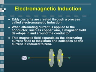
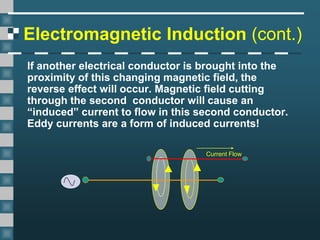
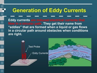
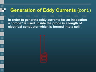
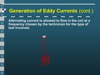
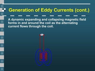
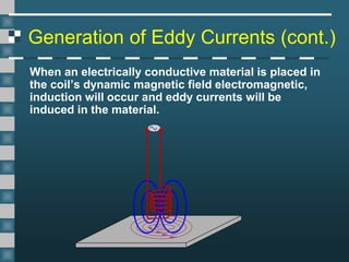
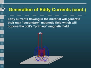
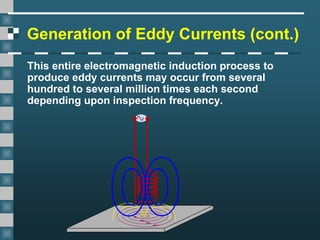
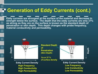
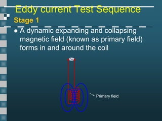
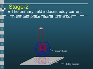
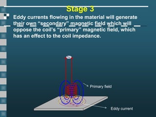
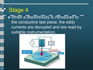
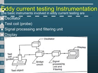
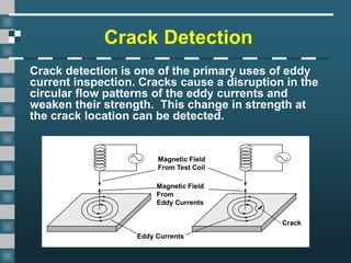
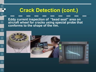
NON DESTRUCTIVE
TESTING AND MATERIALS
ME6019
Unit-3
EDDY CURRENT TESTING
By
Godwin Pithalis.N.E
EDDY CURRENT TESTING
Principle:
EDDY CURRENT TESTING works on the basis of
electromagnetic induction. Eddy currents are
induced in a test object using alternative
electromagnetic field. Flaw in the tested object
causes changes in the eddy current and flow
pattern is observed. This change in the current
field is useful to identify the defect.
Electromagnetic Induction
 Eddy currents are created through a process
called electromagnetic induction.
 When alternating current is applied to the
conductor, such as copper wire, a magnetic field
develops in and around the conductor.
 This magnetic field expands as the alternating
current rises to maximum and collapses as the
current is reduced to zero.
Electromagnetic Induction (cont.)
If another electrical conductor is brought into the
proximity of this changing magnetic field, the
reverse effect will occur. Magnetic field cutting
through the second conductor will cause an
“induced” current to flow in this second conductor.
Eddy currents are a form of induced currents!
Current Flow
Generation of Eddy Currents
Eddy currents are induced electrical currents that
flow in a circular path. They get their name from
“eddies” that are formed when a liquid or gas flows
in a circular path around obstacles when conditions
are right.
Test Probe
Eddy Currents
Generation of Eddy Currents (cont.)
In order to generate eddy currents for an inspection
a “probe” is used. Inside the probe is a length of
electrical conductor which is formed into a coil.
Generation of Eddy Currents (cont.)
Alternating current is allowed to flow in the coil at a
frequency chosen by the technician for the type of
test involved.
Generation of Eddy Currents (cont.)
A dynamic expanding and collapsing magnetic field
forms in and around the coil as the alternating
current flows through the coil.
Generation of Eddy Currents (cont.)
When an electrically conductive material is placed in
the coil’s dynamic magnetic field electromagnetic,
induction will occur and eddy currents will be
induced in the material.
Generation of Eddy Currents (cont.)
Eddy currents flowing in the material will generate
their own “secondary” magnetic field which will
oppose the coil’s “primary” magnetic field.
Generation of Eddy Currents (cont.)
This entire electromagnetic induction process to
produce eddy currents may occur from several
hundred to several million times each second
depending upon inspection frequency.
Depth
Eddy Current Density
Depth
Eddy Current Density
Low Frequency
Low Conductivity
Low Permeability
High Frequency
High Conductivity
High Permeability
Standard Depth
of
Penetration
(Skin Depth)
1/e or 37 %
of surface density
Generation of Eddy Currents (cont.)
Eddy currents are strongest at the surface of the material and decrease in
strength below the surface. The depth that the eddy currents are only 37%
as strong as they are on the surface is known as the standard depth of
penetration or skin depth. This depth changes with probe frequency,
material conductivity and permeability.
Eddy current Test Sequence
Stage 1
 A dynamic expanding and collapsing
magnetic field (known as primary field)
forms in and around the coil
Primary field
Stage-2
 The primary field induces eddy current
in the test piece nearer to the coil
Primary field
Eddy current
Stage 3
Eddy currents flowing in the material will generate
their own “secondary” magnetic field which will
oppose the coil’s “primary” magnetic field, which
has an effect to the coil impedance.
Primary field
Eddy current
Stage 4
 When a discontinuity is introduced to
the conductive test piece, the eddy
currents are disrupted and are read by
suitable instrumentation.
Eddy current testing Instrumentation
The basic instruments involved in eddy current testing are
 Oscillator
 Test coil (probe)
 Signal processing and filtering unit
 Display
1.Oscillator
 The oscillator provides an alternating current of the required
frequency to the test
2. Test Coil (probe)
 It serves as the main link between test instrument and test
object
 It establishes a varying electromagnetic field, which induces
the eddy current in the test object and increases the
magnetic effect in magnetic materials
 It also senses the current flow and magnetic effect within the
test object and feeds the information to the signal analysis
system
Types –(i) Encircling
 (ii) Coil inside the test object
 (iii) Surface coil
3.Signal processing & Filtering
 In eddy current testing, the signals of defects may be
corrupted by noise and other non-defect signals arising
from the probe lift-off and the structures attached with test
object.
 This results undesirable detection and inaccurate
characterization of defects.
 Correct filter settings can significantly improve the visibility
of the defect signal, whereas incorrect settings can distort
the signal presentation.
Commonly used filters
 (i) High pass filter (HPF)
 (ii) Low pass filter (LPF)
4.Displays
 Displays can range from single LED and
meter readouts to multi-frequency
presentations on display screens
 (i) Dedicated display instrument
 (ii) Impedance plane display instrument
Applications
1.Material property determination
 Heat treatment evaluations
 Hardness
 Impurities
 Chemical compositions
 Corrosion damage
2.Thickness measurement
 Thin sheet metal
 Foil
 Paints
 Anodic coatings
 Thin insulation
Applications(contd)
3.Flaw Detection
 Testing of casted, welded, forged and
rolled products
 Detection of cracks or discontinuity in
bolts, nuts etc
 Inspection of railway components
 Determining defects in aerospace parts
 Inspection of tubes of heat exchanger,
boiler etc
Crack Detection
Crack detection is one of the primary uses of eddy
current inspection. Cracks cause a disruption in the
circular flow patterns of the eddy currents and
weaken their strength. This change in strength at
the crack location can be detected.
Magnetic Field
From Test Coil
Magnetic Field
From
Eddy Currents
Eddy Currents
Crack
Crack Detection (cont.)
Eddy current inspection is exceptionally well suited
for the detection of cracks, with an especially high
sensitivity to detection of surface breaking cracks.
Crack Detection (cont.)
Eddy current inspection of “bead seat” area on
aircraft wheel for cracks using special probe that
conforms to the shape of the rim.
Advantages of Eddy Current
Inspection
• Sensitive to small cracks and other defects
• Detects surface and near surface defects
• Inspection gives immediate results (High speed test)
• Equipment is portable
• Method can be used for much more than flaw
detection
• Minimum part preparation is required
• Test probe does not need to contact the part
• Inspects complex shapes and sizes of conductive
materials
Limitations of Eddy Current
Inspection
• Only conductive materials can be inspected
• Surface must be accessible to the probe
• No permanent record is possible
• Skill and training required is more extensive than
other techniques
• Surface finish and roughness may interfere
• Reference standards needed for setup
• Depth of penetration is limited
• Flaws such as delaminations that lie parallel to the
probe coil winding and probe scan direction are
undetectable

Ndtm 3-eddy current

  • 1.
    NON DESTRUCTIVE TESTING ANDMATERIALS ME6019 Unit-3 EDDY CURRENT TESTING By Godwin Pithalis.N.E
  • 2.
    EDDY CURRENT TESTING Principle: EDDYCURRENT TESTING works on the basis of electromagnetic induction. Eddy currents are induced in a test object using alternative electromagnetic field. Flaw in the tested object causes changes in the eddy current and flow pattern is observed. This change in the current field is useful to identify the defect.
  • 3.
    Electromagnetic Induction  Eddycurrents are created through a process called electromagnetic induction.  When alternating current is applied to the conductor, such as copper wire, a magnetic field develops in and around the conductor.  This magnetic field expands as the alternating current rises to maximum and collapses as the current is reduced to zero.
  • 4.
    Electromagnetic Induction (cont.) Ifanother electrical conductor is brought into the proximity of this changing magnetic field, the reverse effect will occur. Magnetic field cutting through the second conductor will cause an “induced” current to flow in this second conductor. Eddy currents are a form of induced currents! Current Flow
  • 5.
    Generation of EddyCurrents Eddy currents are induced electrical currents that flow in a circular path. They get their name from “eddies” that are formed when a liquid or gas flows in a circular path around obstacles when conditions are right. Test Probe Eddy Currents
  • 6.
    Generation of EddyCurrents (cont.) In order to generate eddy currents for an inspection a “probe” is used. Inside the probe is a length of electrical conductor which is formed into a coil.
  • 7.
    Generation of EddyCurrents (cont.) Alternating current is allowed to flow in the coil at a frequency chosen by the technician for the type of test involved.
  • 8.
    Generation of EddyCurrents (cont.) A dynamic expanding and collapsing magnetic field forms in and around the coil as the alternating current flows through the coil.
  • 9.
    Generation of EddyCurrents (cont.) When an electrically conductive material is placed in the coil’s dynamic magnetic field electromagnetic, induction will occur and eddy currents will be induced in the material.
  • 10.
    Generation of EddyCurrents (cont.) Eddy currents flowing in the material will generate their own “secondary” magnetic field which will oppose the coil’s “primary” magnetic field.
  • 11.
    Generation of EddyCurrents (cont.) This entire electromagnetic induction process to produce eddy currents may occur from several hundred to several million times each second depending upon inspection frequency.
  • 12.
    Depth Eddy Current Density Depth EddyCurrent Density Low Frequency Low Conductivity Low Permeability High Frequency High Conductivity High Permeability Standard Depth of Penetration (Skin Depth) 1/e or 37 % of surface density Generation of Eddy Currents (cont.) Eddy currents are strongest at the surface of the material and decrease in strength below the surface. The depth that the eddy currents are only 37% as strong as they are on the surface is known as the standard depth of penetration or skin depth. This depth changes with probe frequency, material conductivity and permeability.
  • 13.
    Eddy current TestSequence Stage 1  A dynamic expanding and collapsing magnetic field (known as primary field) forms in and around the coil Primary field
  • 14.
    Stage-2  The primaryfield induces eddy current in the test piece nearer to the coil Primary field Eddy current
  • 15.
    Stage 3 Eddy currentsflowing in the material will generate their own “secondary” magnetic field which will oppose the coil’s “primary” magnetic field, which has an effect to the coil impedance. Primary field Eddy current
  • 16.
    Stage 4  Whena discontinuity is introduced to the conductive test piece, the eddy currents are disrupted and are read by suitable instrumentation.
  • 17.
    Eddy current testingInstrumentation The basic instruments involved in eddy current testing are  Oscillator  Test coil (probe)  Signal processing and filtering unit  Display
  • 18.
    1.Oscillator  The oscillatorprovides an alternating current of the required frequency to the test 2. Test Coil (probe)  It serves as the main link between test instrument and test object  It establishes a varying electromagnetic field, which induces the eddy current in the test object and increases the magnetic effect in magnetic materials  It also senses the current flow and magnetic effect within the test object and feeds the information to the signal analysis system Types –(i) Encircling  (ii) Coil inside the test object  (iii) Surface coil
  • 19.
    3.Signal processing &Filtering  In eddy current testing, the signals of defects may be corrupted by noise and other non-defect signals arising from the probe lift-off and the structures attached with test object.  This results undesirable detection and inaccurate characterization of defects.  Correct filter settings can significantly improve the visibility of the defect signal, whereas incorrect settings can distort the signal presentation. Commonly used filters  (i) High pass filter (HPF)  (ii) Low pass filter (LPF)
  • 20.
    4.Displays  Displays canrange from single LED and meter readouts to multi-frequency presentations on display screens  (i) Dedicated display instrument  (ii) Impedance plane display instrument
  • 21.
    Applications 1.Material property determination Heat treatment evaluations  Hardness  Impurities  Chemical compositions  Corrosion damage 2.Thickness measurement  Thin sheet metal  Foil  Paints  Anodic coatings  Thin insulation
  • 22.
    Applications(contd) 3.Flaw Detection  Testingof casted, welded, forged and rolled products  Detection of cracks or discontinuity in bolts, nuts etc  Inspection of railway components  Determining defects in aerospace parts  Inspection of tubes of heat exchanger, boiler etc
  • 23.
    Crack Detection Crack detectionis one of the primary uses of eddy current inspection. Cracks cause a disruption in the circular flow patterns of the eddy currents and weaken their strength. This change in strength at the crack location can be detected. Magnetic Field From Test Coil Magnetic Field From Eddy Currents Eddy Currents Crack
  • 24.
    Crack Detection (cont.) Eddycurrent inspection is exceptionally well suited for the detection of cracks, with an especially high sensitivity to detection of surface breaking cracks.
  • 25.
    Crack Detection (cont.) Eddycurrent inspection of “bead seat” area on aircraft wheel for cracks using special probe that conforms to the shape of the rim.
  • 26.
    Advantages of EddyCurrent Inspection • Sensitive to small cracks and other defects • Detects surface and near surface defects • Inspection gives immediate results (High speed test) • Equipment is portable • Method can be used for much more than flaw detection • Minimum part preparation is required • Test probe does not need to contact the part • Inspects complex shapes and sizes of conductive materials
  • 27.
    Limitations of EddyCurrent Inspection • Only conductive materials can be inspected • Surface must be accessible to the probe • No permanent record is possible • Skill and training required is more extensive than other techniques • Surface finish and roughness may interfere • Reference standards needed for setup • Depth of penetration is limited • Flaws such as delaminations that lie parallel to the probe coil winding and probe scan direction are undetectable