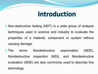
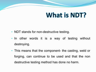
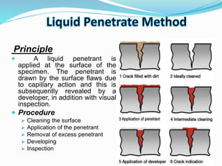
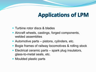
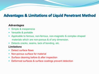
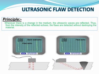
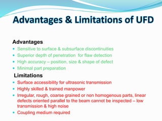
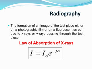
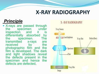
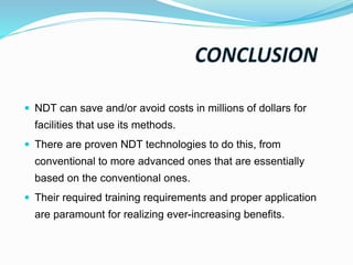
Submitted To: Submitted By:
Department of Mech. Engg. MAJU Jamshed Alam
Course: B.Tech (ME)
3rd Year
Roll No-1601050007
 Introduction
 What is NDT
 Applications
 Objectives
 Types
 liquid penetrant method
 Advantages
 Ultrasonic flaw detection
 Radiography
 References
 Non-destructive testing (NDT) is a wide group of analysis
techniques used in science and industry to evaluate the
properties of a material, component or system without
causing damage.
 The terms Nondestructive examination (NDE),
Nondestructive inspection (NDI), and Nondestructive
evaluation (NDE) are also commonly used to describe this
technology.
• NDT stands for non-destructive testing.
• In other words it is a way of testing without
destroying.
• This means that the component- the casting, weld or
forging, can continue to be used and that the non
destructive testing method has done no harm.
Inspection of Raw Products
Inspection Following Secondary
Processing
In-Services Damage Inspection
 To avoid failures, prevent accidents and save human life.
 To make a profit for the user.
 To ensure customer satisfaction and maintain the manufacturer's
reputation.
 To aid in better product design.
 To control manufacturing processes.
 To lower manufacturing costs
1. Visual Inspection
2. Liquid penetrant method
3. Ultrasonic Inspection
4. Radiography methods
a) X-ray radiography & fluoroscopy
b) γ- ray radiography
5. Eddy current testing
6. Magnetic particle testing
7. Thermography
Principle
 A liquid penetrant is
applied at the surface of the
specimen. The penetrant is
drawn by the surface flaws due
to capillary action and this is
subsequently revealed by a
developer, in addition with visual
inspection.
 Procedure
 Cleaning the surface
 Application of the penetrant
 Removal of excess penetrant
 Developing
 Inspection
 Turbine rotor discs & blades
 Aircraft wheels, castings, forged components,
welded assemblies
 Automotive parts – pistons, cylinders, etc.
 Bogie frames of railway locomotives & rolling stock
 Electrical ceramic parts – spark plug insulators,
glass-to-metal seals, etc.
 Moulded plastic parts
Case Study of spot welding joints of steel sheets with closed
profile by ultrasonic method
Article history:
Available online 9 September 2015
Resistance spot welding is widely
used in the fabrication of vehicle
bodies and parts of their equipment.
The article presents the methodology
and the results of non-destructive
ultrasonic testing of resistance spot
welded joints of thin steel sheet with
closed profile.
Results
Selected results of ultrasonic and mechanical (destructive) tests carried out on a series
of welded joints of steel sheet and closed profile (circular and a rectangular sections) are
summarized in Table1. The most important ultrasonic control parameter is the number of
echoes and the so-calledintermediate echoes, which may indicate an incorrectly
performed joint.
Advantages
 Simple & inexpensive
 Versatile & portable
 Applicable to ferrous, non-ferrous, non-magnetic & complex shaped
materials which are non-porous & of any dimension.
 Detects cracks, seams, lack of bonding, etc.
Limitations
 Detect surface flaws
 Non-porous surface for material
 Surface cleaning before & after inspection
 Deformed surfaces & surface coatings prevent detection
Principle:-
Whenever there is a change in the medium, the ultrasonic waves are reflected. Thus,
from the intensity of the reflected echoes, the flaws are detected without destroying the
material.
 Quality control & material inspection
 Detection of failure of rail rolling stock axes, pressure
columns, earthmoving equipments, mill rolls, mixing
equipments, etc.
 Measurement of metal section thickness
 Thickness measurements – refinery & chemical
processing equipments, submarine hulls, aircraft
sections, pressure vessels, etc.
 Inspect pipe & plate welds
 Inspect pins, bolts & shafts for cracks
 Detect internal corrosion
Advantages
 Sensitive to surface & subsurface discontinuities
 Superior depth of penetration for flaw detection
 High accuracy – position, size & shape of defect
 Minimal part preparation
Limitations
 Surface accessibility for ultrasonic transmission
 Highly skilled & trained manpower
 Irregular, rough, coarse grained or non homogenous parts, linear
defects oriented parallel to the beam cannot be inspected – low
transmission & high noise
 Coupling medium required
 The formation of an image of the test piece either
on a photographic film or on a fluorescent screen
due to x-rays or γ-rays passing through the test
piece.
Law of Absorption of X-rays
x
oeII 

Principle
 X-rays are passed through
the specimen under
inspection and it is
differentially absorbed by
the specimen. The
transmitted x-rays are
received by the
photographic film and the
film is developed. The dark
and light shadows reveal
the defects present in the
specimen and hence the
defects are defected.
Principle
 X-rays are exposed over the specimen by keeping the x-
ray source at position ‘A’ and then at ‘B’ by displacing the
source through a certain distance. The images are
recorded at positions ‘A’ and ‘B’. From the displacements
of the x-ray tube and the images, the exact position of the
defect can be determined.
Principle
 X-rays are passed through
the specimen and is made
to fall on a fluorescent
screen. With respect to the
defects in the specimen,
there will be a variation in
intensity.
Merits
 No need of washing and developing films
 Low cost
 Image viewed immediately on screen
 Time consumption is less
Demerits
 Poor resolution
 Low image contrast
 Electronic image intensifier required for increasing the
contrast
Radiography
1. Image developed on
photographic film
2. High resolution & contrast
3. Immediate image cannot be
obtained.
4. X-ray energy is converted
into chemical energy.
5. It is expensive
6. Time consumption is high.
Fluoroscopy
1. Image is developed on
fluorescent screen.
2. Fair resolution and low
contrast.
3. Immediate image can be
viewed through the monitor.
4. X-ray energy is converted
into visible light.
5. It is inexpensive.
6. Time consumption is low
 Applied directly to the product
 Tested parts are not damaged
 Various tests can be performed on the same product
 Specimen preparation not required
 Can be performed on parts that are in service
 Low time consumption
 Low lab our cost
 Porosity
 Undercutting
 Rollover or “Cold Lap”
 Slag inclusion
 Poor penetration
 Voids
 NDT can save and/or avoid costs in millions of dollars for
facilities that use its methods.
 There are proven NDT technologies to do this, from
conventional to more advanced ones that are essentially
based on the conventional ones.
 Their required training requirements and proper application
are paramount for realizing ever-increasing benefits.
THANK YOU

non-destructive testing ppt

  • 1.
    Submitted To: SubmittedBy: Department of Mech. Engg. MAJU Jamshed Alam Course: B.Tech (ME) 3rd Year Roll No-1601050007
  • 2.
     Introduction  Whatis NDT  Applications  Objectives  Types  liquid penetrant method  Advantages  Ultrasonic flaw detection  Radiography  References
  • 3.
     Non-destructive testing(NDT) is a wide group of analysis techniques used in science and industry to evaluate the properties of a material, component or system without causing damage.  The terms Nondestructive examination (NDE), Nondestructive inspection (NDI), and Nondestructive evaluation (NDE) are also commonly used to describe this technology.
  • 4.
    • NDT standsfor non-destructive testing. • In other words it is a way of testing without destroying. • This means that the component- the casting, weld or forging, can continue to be used and that the non destructive testing method has done no harm.
  • 5.
    Inspection of RawProducts Inspection Following Secondary Processing In-Services Damage Inspection
  • 6.
     To avoidfailures, prevent accidents and save human life.  To make a profit for the user.  To ensure customer satisfaction and maintain the manufacturer's reputation.  To aid in better product design.  To control manufacturing processes.  To lower manufacturing costs
  • 7.
    1. Visual Inspection 2.Liquid penetrant method 3. Ultrasonic Inspection 4. Radiography methods a) X-ray radiography & fluoroscopy b) γ- ray radiography 5. Eddy current testing 6. Magnetic particle testing 7. Thermography
  • 8.
    Principle  A liquidpenetrant is applied at the surface of the specimen. The penetrant is drawn by the surface flaws due to capillary action and this is subsequently revealed by a developer, in addition with visual inspection.  Procedure  Cleaning the surface  Application of the penetrant  Removal of excess penetrant  Developing  Inspection
  • 9.
     Turbine rotordiscs & blades  Aircraft wheels, castings, forged components, welded assemblies  Automotive parts – pistons, cylinders, etc.  Bogie frames of railway locomotives & rolling stock  Electrical ceramic parts – spark plug insulators, glass-to-metal seals, etc.  Moulded plastic parts
  • 10.
    Case Study ofspot welding joints of steel sheets with closed profile by ultrasonic method Article history: Available online 9 September 2015 Resistance spot welding is widely used in the fabrication of vehicle bodies and parts of their equipment. The article presents the methodology and the results of non-destructive ultrasonic testing of resistance spot welded joints of thin steel sheet with closed profile.
  • 11.
    Results Selected results ofultrasonic and mechanical (destructive) tests carried out on a series of welded joints of steel sheet and closed profile (circular and a rectangular sections) are summarized in Table1. The most important ultrasonic control parameter is the number of echoes and the so-calledintermediate echoes, which may indicate an incorrectly performed joint.
  • 12.
    Advantages  Simple &inexpensive  Versatile & portable  Applicable to ferrous, non-ferrous, non-magnetic & complex shaped materials which are non-porous & of any dimension.  Detects cracks, seams, lack of bonding, etc. Limitations  Detect surface flaws  Non-porous surface for material  Surface cleaning before & after inspection  Deformed surfaces & surface coatings prevent detection
  • 13.
    Principle:- Whenever there isa change in the medium, the ultrasonic waves are reflected. Thus, from the intensity of the reflected echoes, the flaws are detected without destroying the material.
  • 14.
     Quality control& material inspection  Detection of failure of rail rolling stock axes, pressure columns, earthmoving equipments, mill rolls, mixing equipments, etc.  Measurement of metal section thickness  Thickness measurements – refinery & chemical processing equipments, submarine hulls, aircraft sections, pressure vessels, etc.  Inspect pipe & plate welds  Inspect pins, bolts & shafts for cracks  Detect internal corrosion
  • 15.
    Advantages  Sensitive tosurface & subsurface discontinuities  Superior depth of penetration for flaw detection  High accuracy – position, size & shape of defect  Minimal part preparation Limitations  Surface accessibility for ultrasonic transmission  Highly skilled & trained manpower  Irregular, rough, coarse grained or non homogenous parts, linear defects oriented parallel to the beam cannot be inspected – low transmission & high noise  Coupling medium required
  • 16.
     The formationof an image of the test piece either on a photographic film or on a fluorescent screen due to x-rays or γ-rays passing through the test piece. Law of Absorption of X-rays x oeII  
  • 17.
    Principle  X-rays arepassed through the specimen under inspection and it is differentially absorbed by the specimen. The transmitted x-rays are received by the photographic film and the film is developed. The dark and light shadows reveal the defects present in the specimen and hence the defects are defected.
  • 18.
    Principle  X-rays areexposed over the specimen by keeping the x- ray source at position ‘A’ and then at ‘B’ by displacing the source through a certain distance. The images are recorded at positions ‘A’ and ‘B’. From the displacements of the x-ray tube and the images, the exact position of the defect can be determined.
  • 20.
    Principle  X-rays arepassed through the specimen and is made to fall on a fluorescent screen. With respect to the defects in the specimen, there will be a variation in intensity.
  • 21.
    Merits  No needof washing and developing films  Low cost  Image viewed immediately on screen  Time consumption is less Demerits  Poor resolution  Low image contrast  Electronic image intensifier required for increasing the contrast
  • 22.
    Radiography 1. Image developedon photographic film 2. High resolution & contrast 3. Immediate image cannot be obtained. 4. X-ray energy is converted into chemical energy. 5. It is expensive 6. Time consumption is high. Fluoroscopy 1. Image is developed on fluorescent screen. 2. Fair resolution and low contrast. 3. Immediate image can be viewed through the monitor. 4. X-ray energy is converted into visible light. 5. It is inexpensive. 6. Time consumption is low
  • 23.
     Applied directlyto the product  Tested parts are not damaged  Various tests can be performed on the same product  Specimen preparation not required  Can be performed on parts that are in service  Low time consumption  Low lab our cost
  • 24.
     Porosity  Undercutting Rollover or “Cold Lap”  Slag inclusion  Poor penetration  Voids
  • 25.
     NDT cansave and/or avoid costs in millions of dollars for facilities that use its methods.  There are proven NDT technologies to do this, from conventional to more advanced ones that are essentially based on the conventional ones.  Their required training requirements and proper application are paramount for realizing ever-increasing benefits.
  • 26.

Editor's Notes