Introduction
This moduleis intended to present
information on the NDT method of eddy
current inspection.
Eddy current inspection is one of several
methods that use the principal of
“electromagnetism” as the basis for
conducting examinations. Several other
methods such as Remote Field Testing
(RFT), Flux Leakage and Barkhausen Noise
also use this principle.
3.
Outline
Electromagnetic induction
Generation of eddy currents
Inspection applications
Equipment utilized in eddy current inspection
Probes/Coils
Instrumentation
Reference standard
Advantages and Limitations
Glossary of Terms
4.
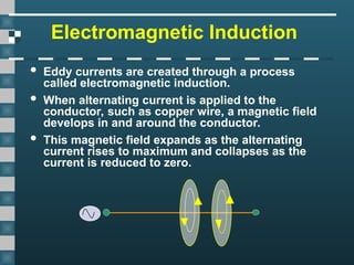
Electromagnetic Induction
Eddycurrents are created through a process
called electromagnetic induction.
When alternating current is applied to the
conductor, such as copper wire, a magnetic field
develops in and around the conductor.
This magnetic field expands as the alternating
current rises to maximum and collapses as the
current is reduced to zero.
5.
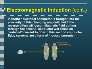
Electromagnetic Induction (cont.)
Ifanother electrical conductor is brought into the
proximity of this changing magnetic field, the
reverse effect will occur. Magnetic field cutting
through the second conductor will cause an
“induced” current to flow in this second conductor.
Eddy currents are a form of induced currents!
Current Flow
6.
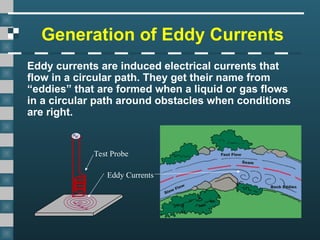
Generation of EddyCurrents
Eddy currents are induced electrical currents that
flow in a circular path. They get their name from
“eddies” that are formed when a liquid or gas flows
in a circular path around obstacles when conditions
are right.
Test Probe
Eddy Currents
7.
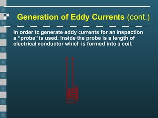
Generation of EddyCurrents (cont.)
In order to generate eddy currents for an inspection
a “probe” is used. Inside the probe is a length of
electrical conductor which is formed into a coil.
8.
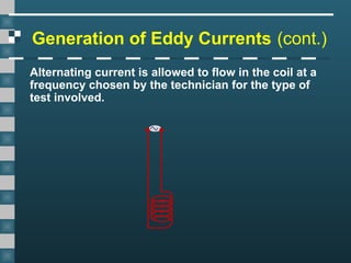
Generation of EddyCurrents (cont.)
Alternating current is allowed to flow in the coil at a
frequency chosen by the technician for the type of
test involved.
9.
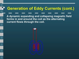
Generation of EddyCurrents (cont.)
A dynamic expanding and collapsing magnetic field
forms in and around the coil as the alternating
current flows through the coil.
10.
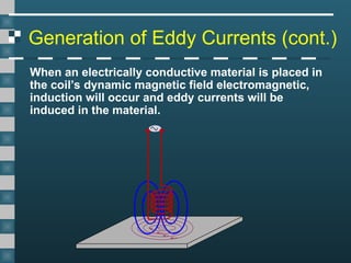
Generation of EddyCurrents (cont.)
When an electrically conductive material is placed in
the coil’s dynamic magnetic field electromagnetic,
induction will occur and eddy currents will be
induced in the material.
11.
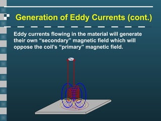
Generation of EddyCurrents (cont.)
Eddy currents flowing in the material will generate
their own “secondary” magnetic field which will
oppose the coil’s “primary” magnetic field.
12.
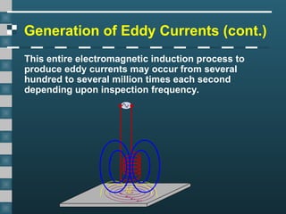
Generation of EddyCurrents (cont.)
This entire electromagnetic induction process to
produce eddy currents may occur from several
hundred to several million times each second
depending upon inspection frequency.
13.
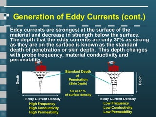
Depth
Eddy Current Density
Depth
EddyCurrent Density
Low Frequency
Low Conductivity
Low Permeability
High Frequency
High Conductivity
High Permeability
Standard Depth
of
Penetration
(Skin Depth)
1/e or 37 %
of surface density
Generation of Eddy Currents (cont.)
Eddy currents are strongest at the surface of the
material and decrease in strength below the surface.
The depth that the eddy currents are only 37% as strong
as they are on the surface is known as the standard
depth of penetration or skin depth. This depth changes
with probe frequency, material conductivity and
permeability.
14.
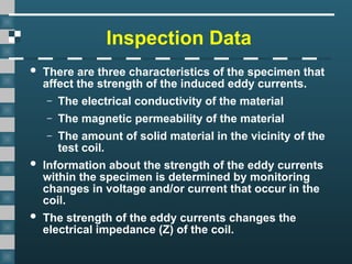
Inspection Data
Thereare three characteristics of the specimen that
affect the strength of the induced eddy currents.
– The electrical conductivity of the material
– The magnetic permeability of the material
– The amount of solid material in the vicinity of the
test coil.
Information about the strength of the eddy currents
within the specimen is determined by monitoring
changes in voltage and/or current that occur in the
coil.
The strength of the eddy currents changes the
electrical impedance (Z) of the coil.
15.
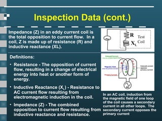
Inspection Data (cont.)
R
~
XL
Test
Coil
Impedance(Z) in an eddy current coil is
the total opposition to current flow. In a
coil, Z is made up of resistance (R) and
inductive reactance (XL).
Definitions:
• Resistance - The opposition of current
flow, resulting in a change of electrical
energy into heat or another form of
energy.
• Inductive Reactance (XL) - Resistance to
AC current flow resulting from
electromagnetic induction in the coil.
• Impedance (Z) - The combined
opposition to current flow resulting from
inductive reactance and resistance.
In an AC coil, induction from
the magnetic field of one loop
of the coil causes a secondary
current in all other loops. The
secondary current opposes the
primary current.
16.
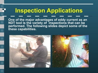
Inspection Applications
One ofthe major advantages of eddy current as an
NDT tool is the variety of inspections that can be
performed. The following slides depict some of the
these capabilities.
17.
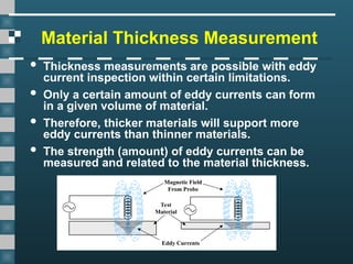
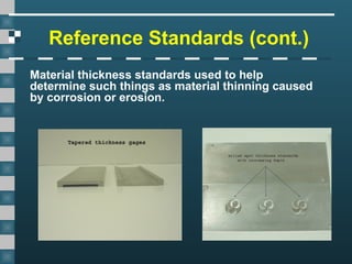
Material Thickness Measurement
Thickness measurements are possible with eddy
current inspection within certain limitations.
Only a certain amount of eddy currents can form
in a given volume of material.
Therefore, thicker materials will support more
eddy currents than thinner materials.
The strength (amount) of eddy currents can be
measured and related to the material thickness.
Eddy Currents
Magnetic Field
From Probe
Test
Material
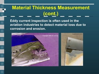
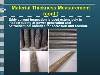
Material Thickness Measurement
(cont.)
Eddycurrent inspection is used extensively to
inspect tubing at power generation and
petrochemical facilities for corrosion and erosion.
20.
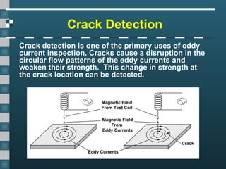
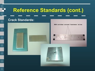
Crack Detection
Crack detectionis one of the primary uses of eddy
current inspection. Cracks cause a disruption in the
circular flow patterns of the eddy currents and
weaken their strength. This change in strength at
the crack location can be detected.
Magnetic Field
From Test Coil
Magnetic Field
From
Eddy Currents
Eddy Currents
Crack
21.
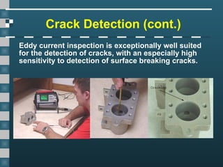
Crack Detection (cont.)
Eddycurrent inspection is exceptionally well suited
for the detection of cracks, with an especially high
sensitivity to detection of surface breaking cracks.
22.
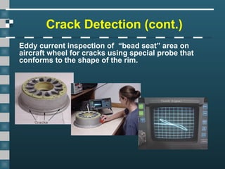
Crack Detection (cont.)
Eddycurrent inspection of “bead seat” area on
aircraft wheel for cracks using special probe that
conforms to the shape of the rim.
23.
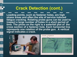
Crack Detection (cont.)
Loadingpoints, such as fastener holes, are high
stress areas and often the site of service induced
fatigue cracking. Rotating probe guns can be used to
inspect a large number of holes in a short period of
time. The photo on the right is a waterfall plot of the
cross section of a fastener hole. Each horizontal line
represents one rotation of the probe gun. A vertical
signal indicates a crack.
24.
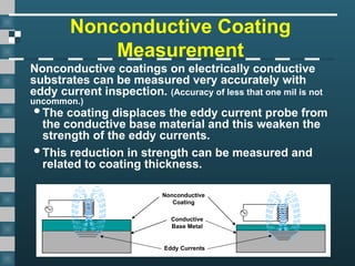
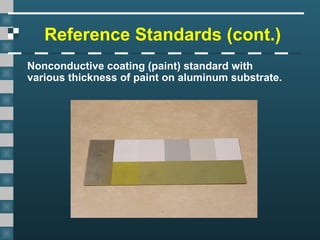
Nonconductive Coating
Measurement
Nonconductive coatingson electrically conductive
substrates can be measured very accurately with
eddy current inspection. (Accuracy of less that one mil is not
uncommon.)
Conductive
Base Metal
Nonconductive
Coating
Eddy Currents
The coating displaces the eddy current probe from
the conductive base material and this weaken the
strength of the eddy currents.
This reduction in strength can be measured and
related to coating thickness.
25.
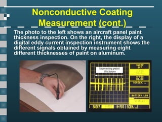
Nonconductive Coating
Measurement (cont.)
Thephoto to the left shows an aircraft panel paint
thickness inspection. On the right, the display of a
digital eddy current inspection instrument shows the
different signals obtained by measuring eight
different thicknesses of paint on aluminum.
Increasing paint
thickness
26.
Monitoring Conductivity and
PermeabilityVariations
Eddy current inspection is sensitive to changes in a
material’s electrical conductivity and magnetic
permeability. This “sensitivity” allows the inspection
method to be used for such inspection procedures as:
•Material Identification
•Material Sorting
•Determination of heat damage
•Cladding and plating thickness measurement
•Heat treatment monitoring
27.
Conductivity Measurements
Boeing employeesin Philadelphia were given the
privilege of evaluating the Liberty Bell for damage
using NDT techniques. Eddy current methods were
used to measure the electrical conductivity of the
Bell's bronze casing at a various points to evaluate
its uniformity.
28.
Equipment
Equipment for eddycurrent inspection is very
diversified. Proper equipment selection is important if
accurate inspection data is desired for a particular
application.
As a minimum, at least three basic pieces of equipment
are needed for any eddy current examination:
– Instrumentation
– Probes
– Reference Standards
29.
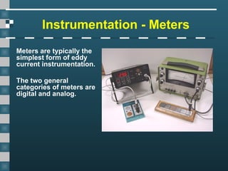
Instrumentation - Meters
Metersare typically the
simplest form of eddy
current instrumentation.
The two general
categories of meters are
digital and analog.
30.
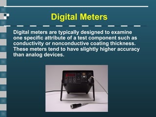
Digital Meters
Digital metersare typically designed to examine
one specific attribute of a test component such as
conductivity or nonconductive coating thickness.
These meters tend to have slightly higher accuracy
than analog devices.
31.
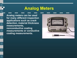
Analog Meters
Analog meterscan be used
for many different inspection
applications such as crack
detection, material thickness
measurements,
nonconductive coating
measurements or conductive
coating measurements.
32.
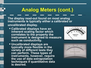
Analog Meters (cont.)
Thedisplay read-out found on most analog
instruments is typically either a calibrated or
uncalibrated display.
•Calibrated displays have an
inherent scaling factor which
correlates to the property the
instrument is designed to measure
such as conductivity.
•Uncalibrated displays are
typically more flexible in the
variety of different tests they
can perform. These types of
instruments, however, require
the use of data extrapolation
techniques if quantitative data
is desired.
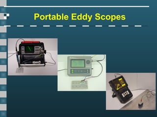
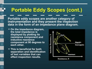
Portable Eddy Scopes(cont.)
Portable eddy scopes are another category of
instrumentation and they present the inspection
data in the form of an impedance plane diagram.
• On the impedance diagram,
the total impedance is
displayed by plotting its
resistance component and
inductive reactance
component at 90 degrees to
each other.
• This is beneficial for both
separation and identification
of test variables that can
effect inspection results.
35.
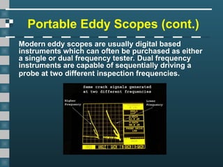
Portable Eddy Scopes(cont.)
Modern eddy scopes are usually digital based
instruments which can often be purchased as either
a single or dual frequency tester. Dual frequency
instruments are capable of sequentially driving a
probe at two different inspection frequencies.
36.
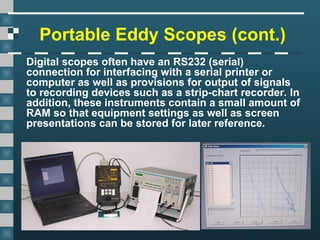
Portable Eddy Scopes(cont.)
Digital scopes often have an RS232 (serial)
connection for interfacing with a serial printer or
computer as well as provisions for output of signals
to recording devices such as a strip-chart recorder. In
addition, these instruments contain a small amount of
RAM so that equipment settings as well as screen
presentations can be stored for later reference.
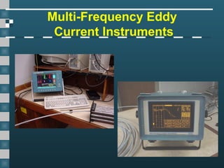
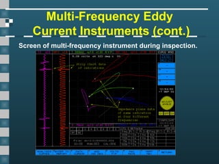
Multi-Frequency Eddy
Current Instruments(cont.)
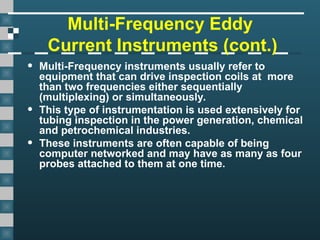
• Multi-Frequency instruments usually refer to
equipment that can drive inspection coils at more
than two frequencies either sequentially
(multiplexing) or simultaneously.
• This type of instrumentation is used extensively for
tubing inspection in the power generation, chemical
and petrochemical industries.
• These instruments are often capable of being
computer networked and may have as many as four
probes attached to them at one time.
39.
Multi-Frequency Eddy
Current Instruments(cont.)
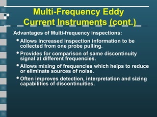
Advantages of Multi-frequency inspections:
Allows increased inspection information to be
collected from one probe pulling.
Provides for comparison of same discontinuity
signal at different frequencies.
Allows mixing of frequencies which helps to reduce
or eliminate sources of noise.
Often improves detection, interpretation and sizing
capabilities of discontinuities.
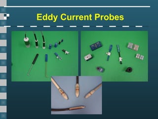
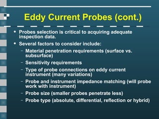
Eddy Current Probes(cont.)
• Probes selection is critical to acquiring adequate
inspection data.
• Several factors to consider include:
– Material penetration requirements (surface vs.
subsurface)
– Sensitivity requirements
– Type of probe connections on eddy current
instrument (many variations)
– Probe and instrument impedance matching (will probe
work with instrument)
– Probe size (smaller probes penetrate less)
– Probe type (absolute, differential, reflection or hybrid)
43.
Eddy Current Probes(cont.)
• Due the the large variety of probes in eddy current
testing there are many different systems of
classification.
• Three of the most common classifications are:
– Surface probes
– Inside Diameter (I.D.) or Bobbin Probes
– Outside Diameter (O.D.) or Encircling probes
44.
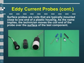
Eddy Current Probes(cont.)
Surface probes are coils that are typically mounted
close to one end of a plastic housing. As the name
implies, the technician moves the coil end of the
probe over the surface of the test component.
45.
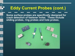
Eddy Current Probes(cont.)
Some surface probes are specifically designed for
crack detection of fastener holes. These include
sliding probes, ring probes and hole probes.
46.
Eddy Current Probes(cont.)
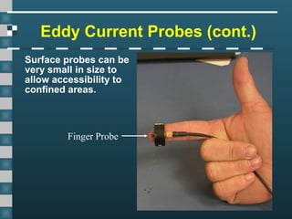
Surface probes can be
very small in size to
allow accessibility to
confined areas.
Finger Probe
47.
Eddy Current Probes(cont.)
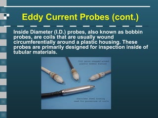
Inside Diameter (I.D.) probes, also known as bobbin
probes, are coils that are usually wound
circumferentially around a plastic housing. These
probes are primarily designed for inspection inside of
tubular materials.
48.
Eddy Current Probes(cont.)
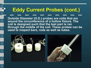
Outside Diameter (O.D.) probes are coils that are
wound the circumference of a hollow fixture. The
coil is designed such that the test part is ran
through the middle of the coil. These probes can be
used to inspect bars, rods as well as tubes.
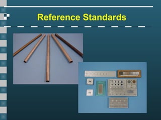
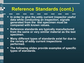
Reference Standards (cont.)
•In order to give the eddy current inspector useful
data while conducting an inspection, signals
generated from the test specimen must be
compared with known values.
• Reference standards are typically manufactured
from the same or very similar material as the test
specimen.
• Many different types of standards exist for due to
the variety of eddy current inspections
performed.
• The following slides provide examples of specific
types of standards.
Advantages of EddyCurrent
Inspection
• Sensitive to small cracks and other defects
• Detects surface and near surface defects
• Inspection gives immediate results
• Equipment is very portable
• Method can be used for much more than flaw
detection
• Minimum part preparation is required
• Test probe does not need to contact the part
• Inspects complex shapes and sizes of conductive
materials
56.
Limitations of EddyCurrent
Inspection
• Only conductive materials can be inspected
• Surface must be accessible to the probe
• Skill and training required is more extensive than
other techniques
• Surface finish and and roughness may interfere
• Reference standards needed for setup
• Depth of penetration is limited
• Flaws such as delaminations that lie parallel to the
probe coil winding and probe scan direction are
undetectable
57.
Glossary of Terms
•Alternating Current: electrical current that regularly
reverses direction.
• Analog: being or relating to a mechanism in which
data is represented by continuously variable physical
quantities such as a watch with hour and minute
hands.
• ASME: acronym for American Society of Mechanical
Engineers. This society is highly involved in
establishing and maintaining industrial standards.
58.
Glossary of Terms
•CRT: acronym for Cathode Ray Tube. Vacuum tube
that uses one or more electron guns for generating
an image.
• Calibration: adjustment of a test systems response
using known values so that unknown quantities may
be derived.
• Conductor: material capable of allowing electrical
current to flow through it.
• Discontinuity: an interruption in the physical
structure of a part. Cracks are examples of
discontinuities.
• EDM: acronym for Electrical Discharge Machine.
59.
Glossary of Terms
•EDM: acronym for Electrical Discharge Machine.
Machining technique which uses an electrode and
electrical current to remove metal. Sometimes used
to prepare calibration standards for eddy current
testing.
• Electromagnetic Induction: process which creates
electrical current flow when a dynamic magnetic field
is brought into close proximity with an electrical
conductor.
• Extrapolation: to project or predict unknown values
from know quantities.
60.
Glossary of Terms
•I.A.C.S.: acronym for International Annealed Copper
Standard. Standard unit of measurement of electrical
conductivity in eddy current testing with pure
annealed copper as the standard, measuring 100%
at 20 degrees Celsius.
• Impedance Plane Diagram: A diagram that depicts
the changes in electrical impedance that occur in an
eddy current coil as test variables change.
• Multiplexing: use of a time sharing system in which
a coil is stimulated at several different frequencies
one after another for a certain amount of time.
Results from each stimulation can then be processed
and displayed.
61.
Glossary of Terms
•Permeability: the ease with which a material can be
magnetized.
• Probe: common term used in eddy current inspection
that refers to the test coil.
• RAM: acronym for Random Access Memory. Most
modern eddy current instruments have some form of
memory used as a data buffer to store information.
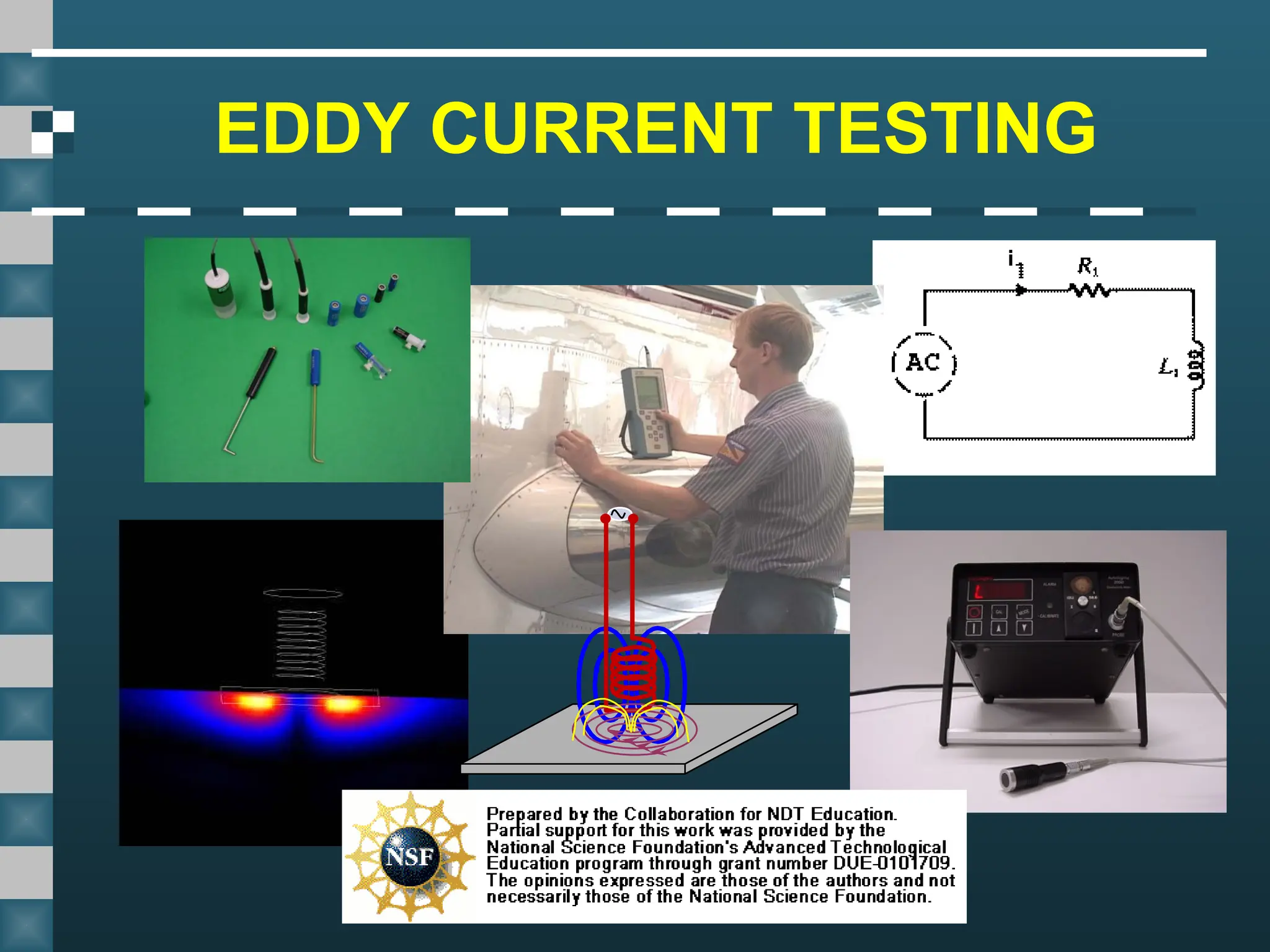
Editor's Notes
#1 This presentation was developed to provide students in industrial technology programs, such as welding, an introduction to magnetic particle testing. The material by itself is not intended to train individuals to perform NDT functions but rather to acquaint individuals with the NDT equipment and methods that they are likely to encounter in industry. More information has been included than might necessarily be required for a general introduction to the subject as some instructors have requested at least 60 minutes of material. Instructors can modify the presentation to meet their needs by simply hiding slides in the “slide sorter” view of PowerPoint.”
This presentation is one of eight developed by the Collaboration for NDT Education. The topics covered by the other presentations are:
Introduction to Nondestructive Testing
Visual Inspection
Penetrant Testing
Magnetic Particle Testing
Radiographic Testing
Ultrasonic Testing
Welder Certification
All rights are reserved by the authors and the presentation cannot be copied or distributed except by the Collaboration for NDT Education.
A free copy of the presentations can be requested by contacting the Collaboration at NDT-ed@cnde.iastate.edu.
#52 Crack standards come in variety of shapes and sizes, which is controlled by the inspection application. The material should be the same or very close to the material of the component being tested. EDM notches are often used to represent the crack but it should be noted that EDM notches usually give a stronger signal that a crack will. The image on the left has EDM notches of various depths and the two on the right show EDM notches at fastener holes.