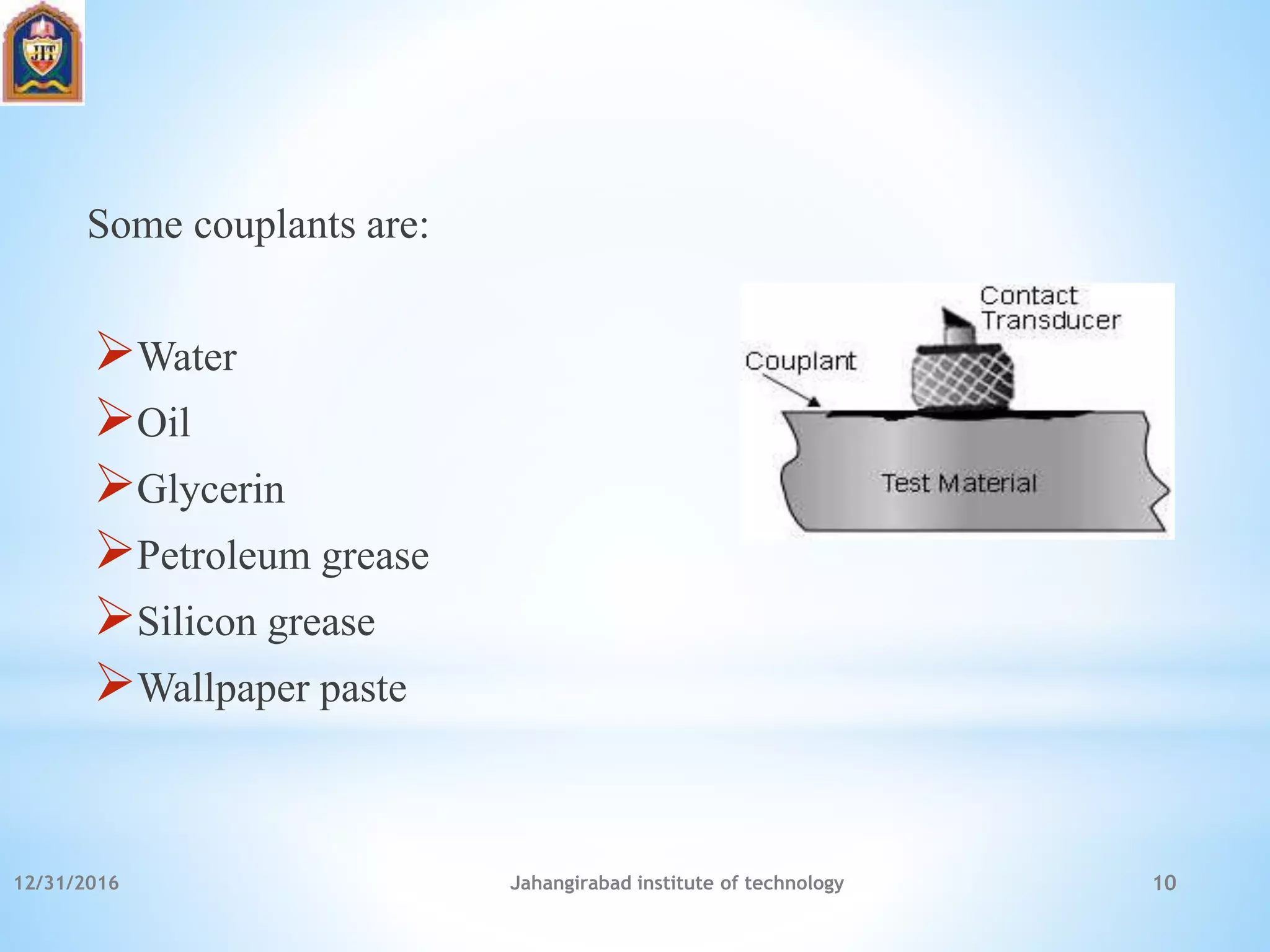
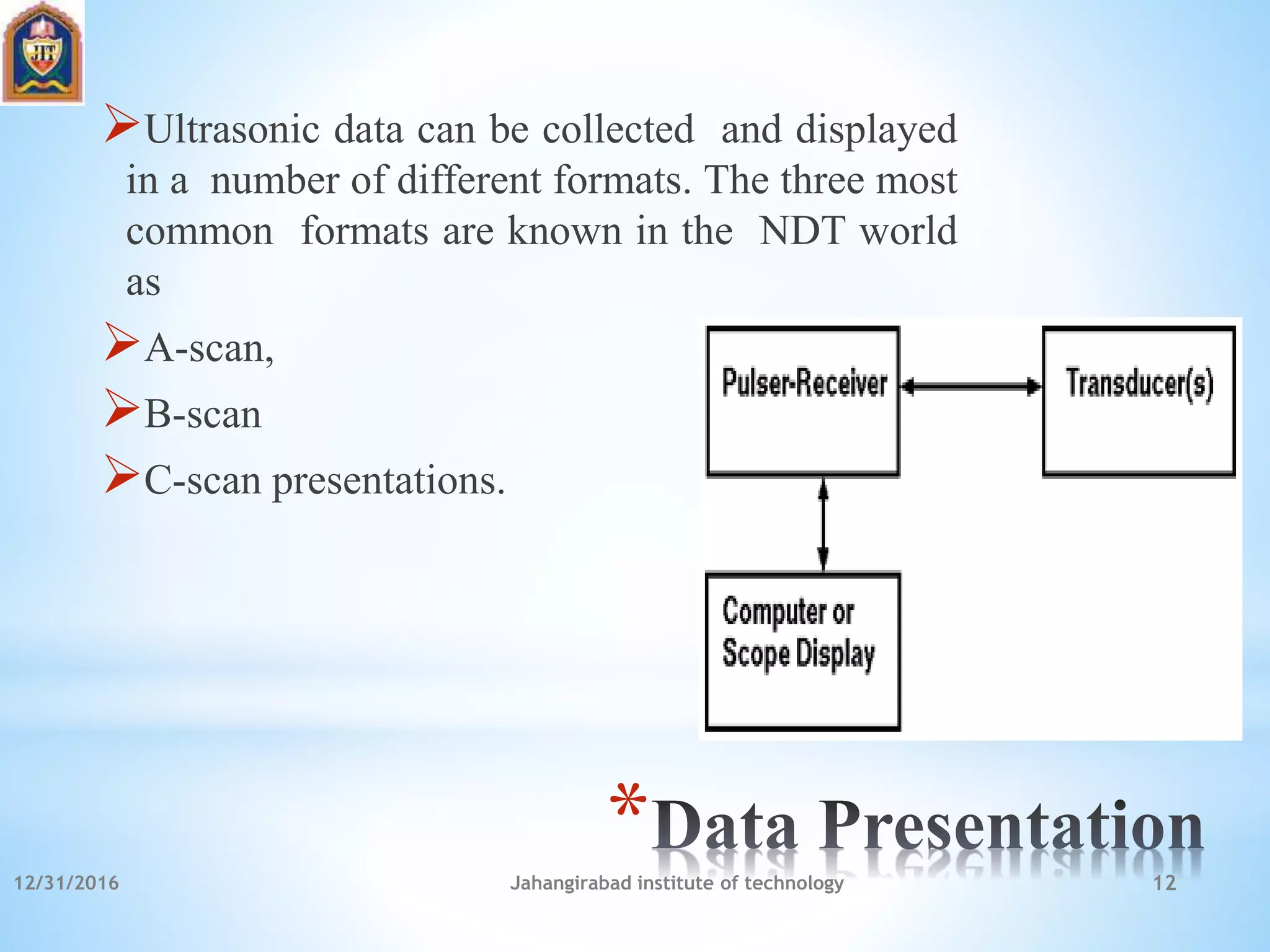
12/31/2016 Jahangirabad institute of technology 1
*
*ULTRASONIC TESTING
*By:
Zoha Nasir
Assistant professor
JIT, Barabanki
*
Ultrasonic detection equipment makes it possible to locate
defects in all types of materials.
Minute cracks, checks, and voids too small to be seen by
x-ray can be located by ultrasonic inspection.
An ultrasonic test instrument requires access to only one
surface of the material to be inspected and can be used with
either straight line or angle beam testing techniques.
12/31/2016 Jahangirabad institute of technology 2
*
Whenever there is a change in the medium, the
ultrasonic waves are reflected. Thus, from the
intensity of the reflected echoes, the flaws are
detected without destroying the material.
12/31/2016 Jahangirabad institute of technology 3
*
Longitudinal wave
Transverse wave
Surface or Rayleigh waves
Lamb or plate waves
12/31/2016 Jahangirabad institute of technology 4
*
Longitudinal (Compression)-Parallel to wave direction
Transverse (Shear)-Perpendicular to wave direction
Surface – Rayleigh- Elliptical orbit - symmetrical mode
Plate Wave – Lamb-Component perpendicular to surface
12/31/2016 Jahangirabad institute of technology 5
*
Two basic methods are used for ultrasonic inspection.
The first of these methods is immersion testing. In this method of inspection,
the part under examination and the search unit are totally immersed in a
liquid couplant, which may be water or any other suitable fluid.
The second method is called contact testing, which is readily adapted to field
use and is the method discussed in this chapter. In this method, the part under
examination and the search unit are coupled with a viscous material, liquid or
a paste, which wets both the face of the search unit and the material under
examination.
There are three basic ultrasonic inspection methods:
(1) Pulse Echo.
(2) Through Transmission.
(3) Resonance.
12/31/2016 Jahangirabad institute of technology 6
*
Piezoelectric Transducers:
 The conversion of electrical pulses to mechanical vibrations and the conversion of
returned mechanical vibrations back into electrical energy is the basis for ultrasonic
testing.
 This conversion is done by the transducer using a piece of piezoelectric material (a
polarized material having some parts of the molecule positively charged, while other parts
of the molecule are negatively charged) with electrodes attached to two of its opposite
faces.
 When an electric field is applied across the material, the polarized molecules will align
themselves with the electric field causing the material to change dimensions.
 In addition, a permanently-polarized material such as quartz (SiO2) or barium titanate
(BaTiO3) will produce an electric field when the material changes dimensions as a result of
an imposed mechanical force. This phenomenon is known as the piezoelectric effect.
12/31/2016 Jahangirabad institute of technology 7
*
Transducers are classified into two major groups according to
the application
Contact Transducers
Immersion Transducers
12/31/2016 Jahangirabad institute of technology 8
*
A couplant is a material (usually liquid) that facilitates the transmission of
ultrasonic energy from the transducer into the test specimen.
Couplant is generally necessary because the acoustic impedance mismatch
between air and solids is large. Therefore, nearly all of the energy is
reflected and very little is transmitted into the test material.
The couplant displaces the air and makes it possible to get more sound
energy into the test specimen so that a usable ultrasonic signal can be
obtained.
In contact ultrasonic testing a thin film of oil, glycerin or water is typically
used between the transducer and the test surface.
When shear waves are to be transmitted, the fluid is generally selected to
have a significant viscosity.
12/31/2016 Jahangirabad institute of technology 9
Some couplants are:
Water
Oil
Glycerin
Petroleum grease
Silicon grease
Wallpaper paste
12/31/2016 Jahangirabad institute of technology 10
*
Ultrasonic pulse-receivers are well suited to general purpose
ultrasonic testing.
Along with appropriate transducers and an oscilloscope, they
can be used for flaw detection and thickness gauging in a wide
variety of metals, plastics, ceramics, and composites.
Ultrasonic pulse-receivers provide a unique, low-cost
ultrasonic measurement capability.
12/31/2016 Jahangirabad institute of technology 11
*
Ultrasonic data can be collected and displayed
in a number of different formats. The three most
common formats are known in the NDT world
as
A-scan,
B-scan
C-scan presentations.
12/31/2016 Jahangirabad institute of technology 12
*
The A scan presentation displays the amount of received
ultrasonic energy as a function of time.
The relative amount of received energy is plotted along the
vertical axis and the elapsed time (which may be related to the
traveled distance within the material) is displayed along the
horizontal axis.
12/31/2016 Jahangirabad institute of technology 13
*
It is possible for automated linear scanning systems where it
shows a profile (cross-sectional) view of the test specimen.
In the B-scan, the time-of-flight (travel time) of the sound
waves is displayed along the vertical axis and the linear
position of the transducer is displayed along the horizontal axis.
From the B-scan, the depth of the reflector and its approximate
linear dimensions in the scan direction can be determined.
The B-scan is typically produced by establishing a trigger gate
on the A-scan.
12/31/2016 Jahangirabad institute of technology 14
*
The C-scan presentation is a type of presentation that is
possible for automated two-dimensional scanning systems
that provides a plan-type view of the location and size of
test specimen features.
The plane of the image is parallel to the scan pattern of the
transducer.
C-scan presentations are typically produced with an
automated data acquisition system, such as a computer
controlled immersion scanning system.
12/31/2016 Jahangirabad institute of technology 15
12/31/2016 Jahangirabad institute of technology 16
*
Porosity
Cracks
Slag
Inclusions
Undercutting
Longitudinal or transverse cracks etc..
12/31/2016 Jahangirabad institute of technology 17
*
Quality control & material inspection.
Detection of failure of rail rolling stock axes, pressure columns,
earthmoving equipment, mill rolls, mixing equipment, etc.
Measurement of metal section thickness.
Thickness measurements – refinery & chemical processing
equipment, submarine hulls, aircraft sections, pressure vessels,
etc.
Inspect pipe & plate welds.
Inspect pins, bolts & shafts for cracks.
Detect internal corrosion.
12/31/2016 Jahangirabad institute of technology 18
*
Sensitive to surface & subsurface discontinuities
Superior depth of penetration for flaw detection
High accuracy – position, size & shape of defect
Minimal part preparation
12/31/2016 Jahangirabad institute of technology 19
*
Surface accessibility for ultrasonic transmission.
 Highly skilled & trained manpower.
 Irregular, rough, coarse grained or non homogenous parts,
linear defects oriented parallel to the beam cannot be inspected
low transmission & high noise.
Coupling medium required.
12/31/2016 Jahangirabad institute of technology 20

Ultrasonic testing

  • 1.
    12/31/2016 Jahangirabad instituteof technology 1 * *ULTRASONIC TESTING *By: Zoha Nasir Assistant professor JIT, Barabanki
  • 2.
    * Ultrasonic detection equipmentmakes it possible to locate defects in all types of materials. Minute cracks, checks, and voids too small to be seen by x-ray can be located by ultrasonic inspection. An ultrasonic test instrument requires access to only one surface of the material to be inspected and can be used with either straight line or angle beam testing techniques. 12/31/2016 Jahangirabad institute of technology 2
  • 3.
    * Whenever there isa change in the medium, the ultrasonic waves are reflected. Thus, from the intensity of the reflected echoes, the flaws are detected without destroying the material. 12/31/2016 Jahangirabad institute of technology 3
  • 4.
    * Longitudinal wave Transverse wave Surfaceor Rayleigh waves Lamb or plate waves 12/31/2016 Jahangirabad institute of technology 4
  • 5.
    * Longitudinal (Compression)-Parallel towave direction Transverse (Shear)-Perpendicular to wave direction Surface – Rayleigh- Elliptical orbit - symmetrical mode Plate Wave – Lamb-Component perpendicular to surface 12/31/2016 Jahangirabad institute of technology 5
  • 6.
    * Two basic methodsare used for ultrasonic inspection. The first of these methods is immersion testing. In this method of inspection, the part under examination and the search unit are totally immersed in a liquid couplant, which may be water or any other suitable fluid. The second method is called contact testing, which is readily adapted to field use and is the method discussed in this chapter. In this method, the part under examination and the search unit are coupled with a viscous material, liquid or a paste, which wets both the face of the search unit and the material under examination. There are three basic ultrasonic inspection methods: (1) Pulse Echo. (2) Through Transmission. (3) Resonance. 12/31/2016 Jahangirabad institute of technology 6
  • 7.
    * Piezoelectric Transducers:  Theconversion of electrical pulses to mechanical vibrations and the conversion of returned mechanical vibrations back into electrical energy is the basis for ultrasonic testing.  This conversion is done by the transducer using a piece of piezoelectric material (a polarized material having some parts of the molecule positively charged, while other parts of the molecule are negatively charged) with electrodes attached to two of its opposite faces.  When an electric field is applied across the material, the polarized molecules will align themselves with the electric field causing the material to change dimensions.  In addition, a permanently-polarized material such as quartz (SiO2) or barium titanate (BaTiO3) will produce an electric field when the material changes dimensions as a result of an imposed mechanical force. This phenomenon is known as the piezoelectric effect. 12/31/2016 Jahangirabad institute of technology 7
  • 8.
    * Transducers are classifiedinto two major groups according to the application Contact Transducers Immersion Transducers 12/31/2016 Jahangirabad institute of technology 8
  • 9.
    * A couplant isa material (usually liquid) that facilitates the transmission of ultrasonic energy from the transducer into the test specimen. Couplant is generally necessary because the acoustic impedance mismatch between air and solids is large. Therefore, nearly all of the energy is reflected and very little is transmitted into the test material. The couplant displaces the air and makes it possible to get more sound energy into the test specimen so that a usable ultrasonic signal can be obtained. In contact ultrasonic testing a thin film of oil, glycerin or water is typically used between the transducer and the test surface. When shear waves are to be transmitted, the fluid is generally selected to have a significant viscosity. 12/31/2016 Jahangirabad institute of technology 9
  • 10.
    Some couplants are: Water Oil Glycerin Petroleumgrease Silicon grease Wallpaper paste 12/31/2016 Jahangirabad institute of technology 10
  • 11.
    * Ultrasonic pulse-receivers arewell suited to general purpose ultrasonic testing. Along with appropriate transducers and an oscilloscope, they can be used for flaw detection and thickness gauging in a wide variety of metals, plastics, ceramics, and composites. Ultrasonic pulse-receivers provide a unique, low-cost ultrasonic measurement capability. 12/31/2016 Jahangirabad institute of technology 11
  • 12.
    * Ultrasonic data canbe collected and displayed in a number of different formats. The three most common formats are known in the NDT world as A-scan, B-scan C-scan presentations. 12/31/2016 Jahangirabad institute of technology 12
  • 13.
    * The A scanpresentation displays the amount of received ultrasonic energy as a function of time. The relative amount of received energy is plotted along the vertical axis and the elapsed time (which may be related to the traveled distance within the material) is displayed along the horizontal axis. 12/31/2016 Jahangirabad institute of technology 13
  • 14.
    * It is possiblefor automated linear scanning systems where it shows a profile (cross-sectional) view of the test specimen. In the B-scan, the time-of-flight (travel time) of the sound waves is displayed along the vertical axis and the linear position of the transducer is displayed along the horizontal axis. From the B-scan, the depth of the reflector and its approximate linear dimensions in the scan direction can be determined. The B-scan is typically produced by establishing a trigger gate on the A-scan. 12/31/2016 Jahangirabad institute of technology 14
  • 15.
    * The C-scan presentationis a type of presentation that is possible for automated two-dimensional scanning systems that provides a plan-type view of the location and size of test specimen features. The plane of the image is parallel to the scan pattern of the transducer. C-scan presentations are typically produced with an automated data acquisition system, such as a computer controlled immersion scanning system. 12/31/2016 Jahangirabad institute of technology 15
  • 16.
  • 17.
    * Porosity Cracks Slag Inclusions Undercutting Longitudinal or transversecracks etc.. 12/31/2016 Jahangirabad institute of technology 17
  • 18.
    * Quality control &material inspection. Detection of failure of rail rolling stock axes, pressure columns, earthmoving equipment, mill rolls, mixing equipment, etc. Measurement of metal section thickness. Thickness measurements – refinery & chemical processing equipment, submarine hulls, aircraft sections, pressure vessels, etc. Inspect pipe & plate welds. Inspect pins, bolts & shafts for cracks. Detect internal corrosion. 12/31/2016 Jahangirabad institute of technology 18
  • 19.
    * Sensitive to surface& subsurface discontinuities Superior depth of penetration for flaw detection High accuracy – position, size & shape of defect Minimal part preparation 12/31/2016 Jahangirabad institute of technology 19
  • 20.
    * Surface accessibility forultrasonic transmission.  Highly skilled & trained manpower.  Irregular, rough, coarse grained or non homogenous parts, linear defects oriented parallel to the beam cannot be inspected low transmission & high noise. Coupling medium required. 12/31/2016 Jahangirabad institute of technology 20