Downloaded 10 times
![1
Faults Detection in Metallic Tubes Using Eddy Current
Prof. Dr. Ali K. Al-Shaikhli .Jabbar M.E. Al-Sudani
And Adil H.Mahmood
Electrical Engineering Deparment Power System Engineering
University ofTechnology.Baghdad.Iraq
______________________________________________________________________________________
Abstract:
Faults in metallic materials can be detected by using eddy current testing system. Metallic tube passes
through a pair of short solenoid coils energized by an alternating current. The rate of decrease in density of
the induced eddy current from the outer surface was determined through the frequency of the energized
current , electrical properties and tube design. Also the investigation shows that the distribution of eddy
currents flowing circumferentially is given in general terms for non-magnetic tube.
Keyword: eddy current, metallic tube, solenoid coils, alternating current, non – magnetic tube.
_______________________________________________________________________________________
Introduction1.
Eddy – current testing may be used to detect
faults, such as cracks in long metal tubes by
passing the tube through a pair of short solenoidal
coils. The coils, which form part of balanced
circuit, are energized by an alternating currents
flow in a circumferential direction round the tube
wall. The circuit containing the coils is balanced
using a uniform tube which is free from faults. An
unbalanced – condition arises when a fault appears
in one side of the coils and the resulting out of
balance voltage can be used to trigger automatic
rejecting mechanisms[1]
.
The signal produced by a given small defect
object under test is proportional to the product of
the current density that would occur at the position
of the defect and the current density that would be
induced thereby a current in the sensing coil
system[2]
.The current density below the surface is
less than the surface current density so that some
means is generally chosen to enhance the signals
from defects below the face[2]
.
Eddy current testing offers severalfeatures that so
welded tube may find to their liking-in particular,
high through speeds and sensitive flaw detection[8]
.
Other advantages are, determining corrosion rate,
environment condition, such as water treatment,
steam and inhibitor condition it can be detect inner
and outer surface corrosion and erosion cracks,and
mechanical wear at support sheets.
Eddy current inspection is a safe method of
testing. With the increased use of new enhanced
tubes, it is critical monitor tube condition. in all
cases, test data is permanently recorded for future
comparison. Results of the examination can be
given on the spot, allowing for a quick response,
and get back on line[7]
.
The main thing in this type of testing is the test coil or
sensor and there are different types from this test coil
like weld seam probes segment test coils and encircling
coils, and there is a special use for each type.
In the test object, the primary magnetic field
created by the test coil is superimposed on the
secondary magnetic field that is produced by the
eddy currents to form the resulting field. The
resulting field in a tested tube is determined by the
following variables:
1. Diameter and wall thickness of the tube.
2. Field strength and frequency of the primary
magnetic fields.
3.Electrical conductivity and magnetic
permeability of the tube.
4. Material defects (crakes, holes, voids, etc.) and
inconsistencies in the tube.
5.Relative motion between the tube and the
excitation system.
2. Mathematical Modling
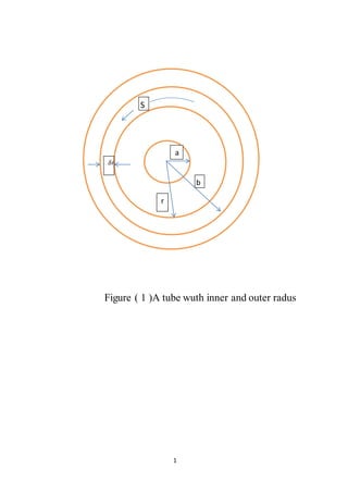
Consider a tube as shown in fig (1). The figure
shows a section through a tube of inner radius (a)
and outer radius (b), r is any point on the wall of
the tube. It is subjected to a magnetic field hb
which is alternating at an angular frequency (𝜔).](https://image.slidesharecdn.com/faultsdetectioninmetallictubesusingeddycurrent-150112141148-conversion-gate01/85/Faults-detection-in-metallic-tubes-using-eddy-current-1-320.jpg)
![1
Faults Detection in Metallic Tubes Using Eddy Current
Prof. Dr. Ali K. Al-Shaikhli .Jabbar M.E. Al-Sudani
And Adil H.Mahmood
Electrical Engineering Deparment Power System Engineering
University ofTechnology.Baghdad.Iraq
______________________________________________________________________________________
Abstract:
Faults in metallic materials can be detected by using eddy current testing system. Metallic tube passes
through a pair of short solenoid coils energized by an alternating current. The rate of decrease in density of
the induced eddy current from the outer surface was determined through the frequency of the energized
current , electrical properties and tube design. Also the investigation shows that the distribution of eddy
currents flowing circumferentially is given in general terms for non-magnetic tube.
Keyword: eddy current, metallic tube, solenoid coils, alternating current, non – magnetic tube.
_______________________________________________________________________________________
Introduction1.
Eddy – current testing may be used to detect
faults, such as cracks in long metal tubes by
passing the tube through a pair of short solenoidal
coils. The coils, which form part of balanced
circuit, are energized by an alternating currents
flow in a circumferential direction round the tube
wall. The circuit containing the coils is balanced
using a uniform tube which is free from faults. An
unbalanced – condition arises when a fault appears
in one side of the coils and the resulting out of
balance voltage can be used to trigger automatic
rejecting mechanisms[1]
.
The signal produced by a given small defect
object under test is proportional to the product of
the current density that would occur at the position
of the defect and the current density that would be
induced thereby a current in the sensing coil
system[2]
.The current density below the surface is
less than the surface current density so that some
means is generally chosen to enhance the signals
from defects below the face[2]
.
Eddy current testing offers severalfeatures that so
welded tube may find to their liking-in particular,
high through speeds and sensitive flaw detection[8]
.
Other advantages are, determining corrosion rate,
environment condition, such as water treatment,
steam and inhibitor condition it can be detect inner
and outer surface corrosion and erosion cracks,and
mechanical wear at support sheets.
Eddy current inspection is a safe method of
testing. With the increased use of new enhanced
tubes, it is critical monitor tube condition. in all
cases, test data is permanently recorded for future
comparison. Results of the examination can be
given on the spot, allowing for a quick response,
and get back on line[7]
.
The main thing in this type of testing is the test coil or
sensor and there are different types from this test coil
like weld seam probes segment test coils and encircling
coils, and there is a special use for each type.
In the test object, the primary magnetic field
created by the test coil is superimposed on the
secondary magnetic field that is produced by the
eddy currents to form the resulting field. The
resulting field in a tested tube is determined by the
following variables:
1. Diameter and wall thickness of the tube.
2. Field strength and frequency of the primary
magnetic fields.
3.Electrical conductivity and magnetic
permeability of the tube.
4. Material defects (crakes, holes, voids, etc.) and
inconsistencies in the tube.
5.Relative motion between the tube and the
excitation system.
2. Mathematical Modling
Consider a tube as shown in fig (1). The figure
shows a section through a tube of inner radius (a)
and outer radius (b), r is any point on the wall of
the tube. It is subjected to a magnetic field hb
which is alternating at an angular frequency (𝜔).](https://image.slidesharecdn.com/faultsdetectioninmetallictubesusingeddycurrent-150112141148-conversion-gate01/75/Faults-detection-in-metallic-tubes-using-eddy-current-1-2048.jpg)


Eddy current testing is employed for fault detection in metallic tubes by measuring the response of induced eddy currents as the tube passes through energized solenoid coils. The method allows for real-time monitoring of defects like cracks and corrosion without physical contact, making it suitable for high-speed production environments. Key advantages include reliability at extreme temperatures, ease of automation, and the ability to integrate into existing processes.