Downloaded 166 times
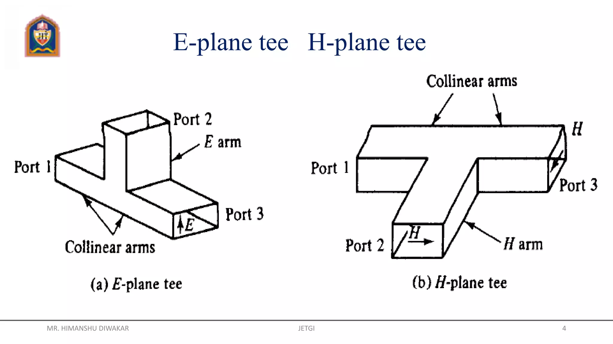
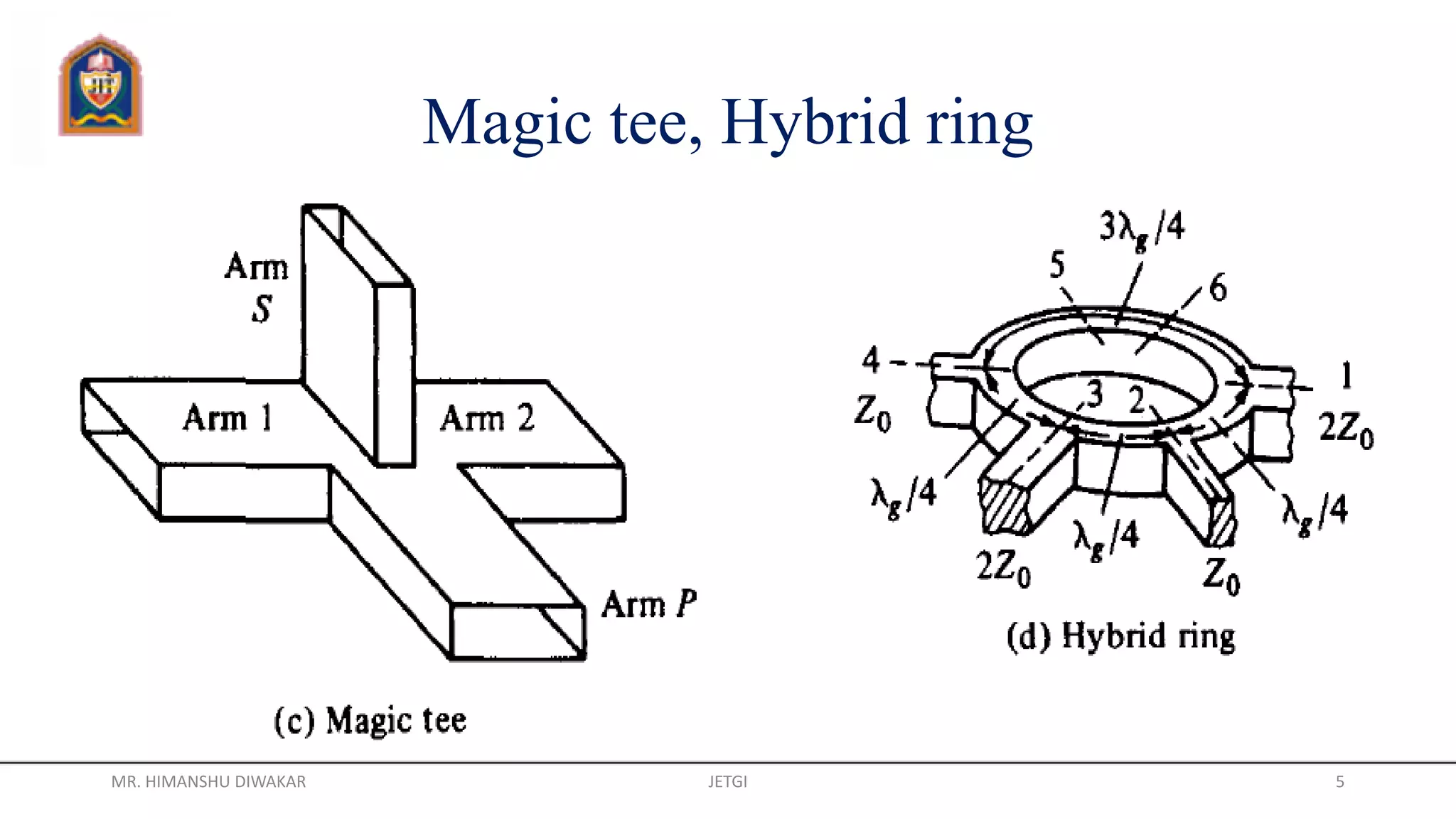

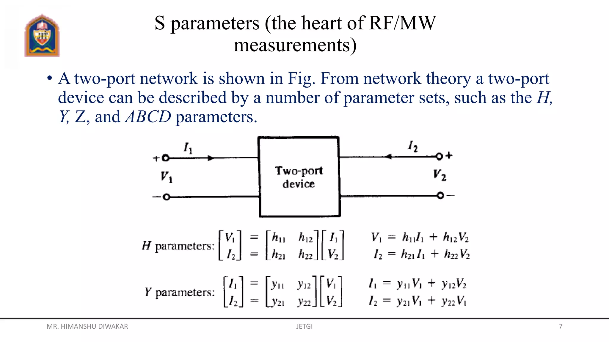


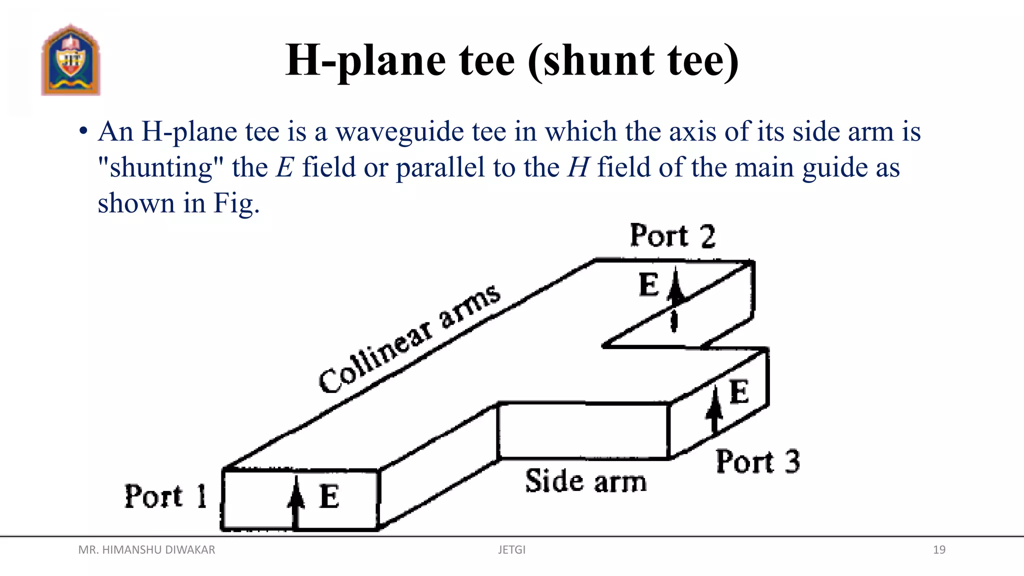


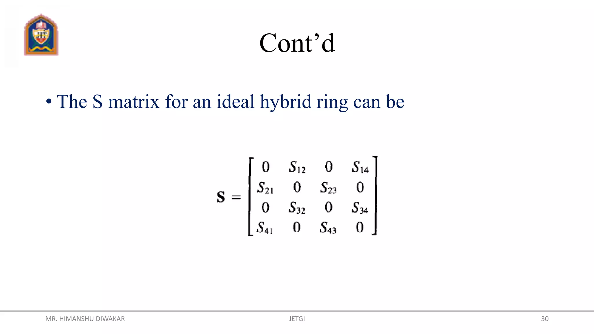


This document discusses various microwave hybrid circuits. It describes E-plane and H-plane tees, which are waveguide junctions with three ports. Magic tees combine properties of E-plane and H-plane tees. Hybrid rings consist of an annular waveguide with four ports, and exhibit similar properties to magic tees. Directional couplers and circulators are also microwave junctions discussed. S-parameters are introduced as a way to characterize microwave networks by measuring traveling waves rather than total voltages and currents.