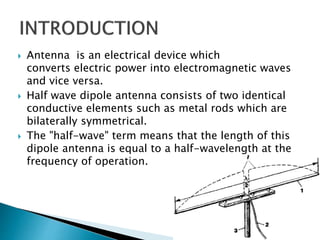
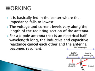
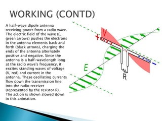
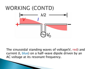
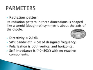
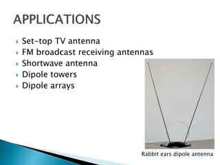
An antenna array (or array antenna) is a set of multiple connected antennas which work together as a single antenna, to transmit or receive radio waves. The individual antenna elements are connected to a single receiver or transmitter by feedlines that feed the power to the elements in a specific phase relationship. The radio waves radiated by each individual antenna combine and superpose, adding together (interfering constructively) to enhance the power radiated in desired directions, and cancelling (interfering destructively) to reduce the power radiated in other directions. Similarly, when used for receiving, the separate radio frequency currents from the individual antennas combine in the receiver with the correct phase relationship to enhance signals received from the desired directions and cancel signals from undesired directions.
An Antenna is a transducer, which converts electrical power into electromagnetic waves and vice versa.
An Antenna can be used either as a transmitting antenna or a receiving antenna.
A transmitting antenna is one, which converts electrical signals into electromagnetic waves and radiates them.
A receiving antenna is one, which converts electromagnetic waves from the received beam into electrical signals.
In two-way communication, the same antenna can be used for both transmission and reception.
Basic Parameters
Frequency
Wavelength
Impedance matching
VSWR & reflected power
Bandwidth
Percentage bandwidth
Radiation intensity.
By completing this presentation will be have a clear idea about Antenna's working principles, Antenna's Types & Antenna's Parameters. At the end to this document you'll have a brief idea about Antenna's Tilt vs Distance Calculation & Cluster wise optimum Antenna Selection procedure. Impact of antenna PIM & VSWR have been described elaborately in this document as well.
hello readers i give my PPT presentation for about antenna and ther properties and working explain in this ppt
i hope you like it THANK YOU.......!!!!!!!
A horn antenna or microwave horn is an antenna that consists of a flaring metal waveguide shaped like a horn to direct radio waves in a beam. Horns are widely used as antennas at UHF and microwave frequencies, above 300 MHz.
MicroStrip Antenna
Introduction .
Micro-Strip Antennas Types .
Micro-Strip Antennas Shapes .
Types of Substrates (Dielectric Media) .
Comparison of various types of flat profile printed antennas .
Advantages & DisAdvantages of MSAs .
Applications of MSAs .
Radiation patterns of MSAs .
How to Optimizing the Substrate Properties for Increased Bandwidth ?
Comparing the different feed techniques .
This presentation is about antennas and covers the following topics:
-Antenna
-Hertzian dipole
-Half wave dipole
-Dipole antenna
-Quarter wave monopole antenna
-Antenna characteristics
This presentation is as per the course of DAE Electronics ELECT-212.
In our daily life we see so many antennas everywhere, from simple radio transreceiver to big tower antennas and DTH antennas. Antenna is a magical element in the field of communication. Nobody can dream of wireless communication without the use of antennas. It’s the antenna which creates the magic in the air and makes wireless communication possible.
In this paper authors will discuss about the cellular antennas. They will concentrate mainly on fundamentals of antenna, relationship between frequency, wavelength and dipole wave propagation and parameters of antenna like Gain, VSWR, SFR and FBR etc.
Authors also discuss about types of down tilt, generic requirements of antennas, selection of antennas and beam forming and active antenna systems.
About
Indigenized remote control interface card suitable for MAFI system CCR equipment. Compatible for IDM8000 CCR. Backplane mounted serial and TCP/Ethernet communication module for CCR remote access. IDM 8000 CCR remote control on serial and TCP protocol.
• Remote control: Parallel or serial interface.
• Compatible with MAFI CCR system.
• Compatible with IDM8000 CCR.
• Compatible with Backplane mount serial communication.
• Compatible with commercial and Defence aviation CCR system.
• Remote control system for accessing CCR and allied system over serial or TCP.
• Indigenized local Support/presence in India.
• Easy in configuration using DIP switches.
Technical Specifications
Indigenized remote control interface card suitable for MAFI system CCR equipment. Compatible for IDM8000 CCR. Backplane mounted serial and TCP/Ethernet communication module for CCR remote access. IDM 8000 CCR remote control on serial and TCP protocol.
Key Features
Indigenized remote control interface card suitable for MAFI system CCR equipment. Compatible for IDM8000 CCR. Backplane mounted serial and TCP/Ethernet communication module for CCR remote access. IDM 8000 CCR remote control on serial and TCP protocol.
• Remote control: Parallel or serial interface
• Compatible with MAFI CCR system
• Copatiable with IDM8000 CCR
• Compatible with Backplane mount serial communication.
• Compatible with commercial and Defence aviation CCR system.
• Remote control system for accessing CCR and allied system over serial or TCP.
• Indigenized local Support/presence in India.
Application
• Remote control: Parallel or serial interface.
• Compatible with MAFI CCR system.
• Compatible with IDM8000 CCR.
• Compatible with Backplane mount serial communication.
• Compatible with commercial and Defence aviation CCR system.
• Remote control system for accessing CCR and allied system over serial or TCP.
• Indigenized local Support/presence in India.
• Easy in configuration using DIP switches.
Industrial Training at Shahjalal Fertilizer Company Limited (SFCL)MdTanvirMahtab2
This presentation is about the working procedure of Shahjalal Fertilizer Company Limited (SFCL). A Govt. owned Company of Bangladesh Chemical Industries Corporation under Ministry of Industries.
Sachpazis:Terzaghi Bearing Capacity Estimation in simple terms with Calculati...Dr.Costas Sachpazis
Terzaghi's soil bearing capacity theory, developed by Karl Terzaghi, is a fundamental principle in geotechnical engineering used to determine the bearing capacity of shallow foundations. This theory provides a method to calculate the ultimate bearing capacity of soil, which is the maximum load per unit area that the soil can support without undergoing shear failure. The Calculation HTML Code included.
NO1 Uk best vashikaran specialist in delhi vashikaran baba near me online vas...Amil Baba Dawood bangali
Contact with Dawood Bhai Just call on +92322-6382012 and we'll help you. We'll solve all your problems within 12 to 24 hours and with 101% guarantee and with astrology systematic. If you want to take any personal or professional advice then also you can call us on +92322-6382012 , ONLINE LOVE PROBLEM & Other all types of Daily Life Problem's.Then CALL or WHATSAPP us on +92322-6382012 and Get all these problems solutions here by Amil Baba DAWOOD BANGALI
#vashikaranspecialist #astrologer #palmistry #amliyaat #taweez #manpasandshadi #horoscope #spiritual #lovelife #lovespell #marriagespell#aamilbabainpakistan #amilbabainkarachi #powerfullblackmagicspell #kalajadumantarspecialist #realamilbaba #AmilbabainPakistan #astrologerincanada #astrologerindubai #lovespellsmaster #kalajaduspecialist #lovespellsthatwork #aamilbabainlahore#blackmagicformarriage #aamilbaba #kalajadu #kalailam #taweez #wazifaexpert #jadumantar #vashikaranspecialist #astrologer #palmistry #amliyaat #taweez #manpasandshadi #horoscope #spiritual #lovelife #lovespell #marriagespell#aamilbabainpakistan #amilbabainkarachi #powerfullblackmagicspell #kalajadumantarspecialist #realamilbaba #AmilbabainPakistan #astrologerincanada #astrologerindubai #lovespellsmaster #kalajaduspecialist #lovespellsthatwork #aamilbabainlahore #blackmagicforlove #blackmagicformarriage #aamilbaba #kalajadu #kalailam #taweez #wazifaexpert #jadumantar #vashikaranspecialist #astrologer #palmistry #amliyaat #taweez #manpasandshadi #horoscope #spiritual #lovelife #lovespell #marriagespell#aamilbabainpakistan #amilbabainkarachi #powerfullblackmagicspell #kalajadumantarspecialist #realamilbaba #AmilbabainPakistan #astrologerincanada #astrologerindubai #lovespellsmaster #kalajaduspecialist #lovespellsthatwork #aamilbabainlahore #Amilbabainuk #amilbabainspain #amilbabaindubai #Amilbabainnorway #amilbabainkrachi #amilbabainlahore #amilbabaingujranwalan #amilbabainislamabad
CFD Simulation of By-pass Flow in a HRSG module by R&R Consult.pptxR&R Consult
CFD analysis is incredibly effective at solving mysteries and improving the performance of complex systems!
Here's a great example: At a large natural gas-fired power plant, where they use waste heat to generate steam and energy, they were puzzled that their boiler wasn't producing as much steam as expected.
R&R and Tetra Engineering Group Inc. were asked to solve the issue with reduced steam production.
An inspection had shown that a significant amount of hot flue gas was bypassing the boiler tubes, where the heat was supposed to be transferred.
R&R Consult conducted a CFD analysis, which revealed that 6.3% of the flue gas was bypassing the boiler tubes without transferring heat. The analysis also showed that the flue gas was instead being directed along the sides of the boiler and between the modules that were supposed to capture the heat. This was the cause of the reduced performance.
Based on our results, Tetra Engineering installed covering plates to reduce the bypass flow. This improved the boiler's performance and increased electricity production.
It is always satisfying when we can help solve complex challenges like this. Do your systems also need a check-up or optimization? Give us a call!
Work done in cooperation with James Malloy and David Moelling from Tetra Engineering.
More examples of our work https://www.r-r-consult.dk/en/cases-en/
3. Antenna is an electrical device which
converts electric power into electromagnetic waves
and vice versa.
Half wave dipole antenna consists of two identical
conductive elements such as metal rods which are
bilaterally symmetrical.
The "half-wave" term means that the length of this
dipole antenna is equal to a half-wavelength at the
frequency of operation.
4. It is basically fed in the center where the
impedance falls to lowest.
The voltage and current levels vary along the
length of the radiating section of the antenna.
For a dipole antenna that is an electrical half
wavelength long, the inductive and capacitive
reactance cancel each other and the antenna
becomes resonant.
5. A half-wave dipole antenna
receiving power from a radio wave.
The electric field of the wave (E,
green arrows) pushes the electrons
in the antenna elements back and
forth (black arrows), charging the
ends of the antenna alternately
positive and negative. Since the
antenna is a half-wavelength long
at the radio wave's frequency, it
excites standing waves of voltage
(V, red) and current in the
antenna. These oscillating currents
flow down the transmission line
into the radio receiver
(represented by the resistor R).
The action is shown slowed down
in this animation.
6. The sinusoidal standing waves of voltage(V, red) and
current (I, blue) on a half-wave dipole driven by an
AC voltage at its resonant frequency.
7. Radiation pattern
Its radiation pattern in three dimensions is shaped
like a toroid (doughnut) symmetric about the axis of
the dipole.
Directivity ≈ 2.1dB.
SWR bandwidth ≈ 5% of designed frequency.
Polarization is both vertical and horizontal.
Self impedance is (40-80)Ω with no reactive
components.
9. It receives balanced signals.
The two pole design enables to receive
signals from a variety of frequencies.
Most of the radiating signal is transmitted
closer to the horizon so, loss is less.
It does not require an antenna “tuner” to work
efficiently.
10. The outdoors antennas are large and wide.
This type of antenna is not used for space
communication.
The installation of outdoors antenna are
difficult.