This document discusses microwave engineering and microwave cavity resonators. It provides details on:
- Microwave cavity resonators, which confine electromagnetic energy inside a metallic enclosure. The resonant frequency depends on the equivalent capacitance, inductance, and resistance of the cavity.
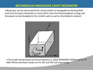
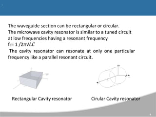
- Rectangular waveguide cavity resonators, which are constructed by shorting both ends of a closed waveguide section to form a cavity.
- The different modes resonant cavities can support and how maximum energy is stored at the resonant frequency.
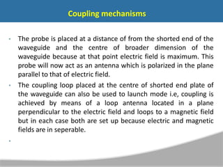
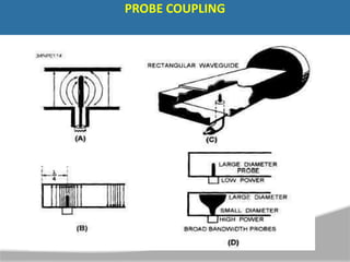
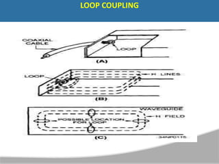
- Common coupling mechanisms like probe coupling and loop coupling to feed or extract signals from the resonator.