Downloaded 790 times

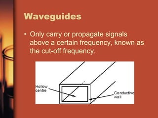
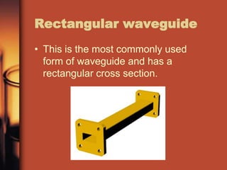
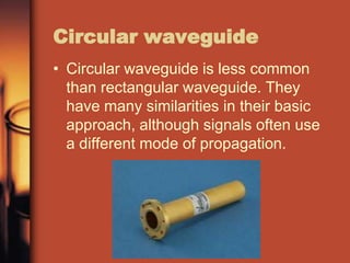

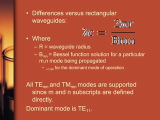
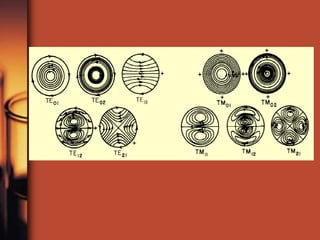

Rectangular waveguides are the most commonly used form and carry signals above a certain cutoff frequency. They propagate electromagnetic waves in different modes depending on whether the electric or magnetic vector is perpendicular to the propagation direction. For rectangular waveguides, the width determines the lower cutoff frequency and the TE10 mode is the lowest supported. Circular waveguides are less common but used when a rotating element is attached; they support all TEmn and TMmn modes with the dominant mode being TE11.


