Download as ODP, PPTX

![Important result for a
good copper
transmission line and w
=constant
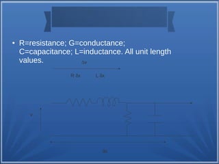
● Z0= [(R+j w L)/(G+j w C)]=characteristic
impedance
● If you have a good copper
transmission line R,G are small, and
● if the signal has a Constant frequency w
● therefore
● Z0=(L/C)1/2= a constant](https://image.slidesharecdn.com/transmissionlineswaveguideantennas-140907143435-phpapp01/85/Transmission-lines-Waveguide-Antennas-9-320.jpg)

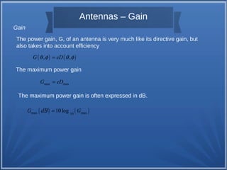
![Antennas – Radiation Patterns
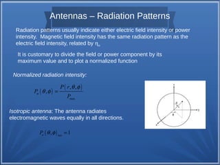
Radiation Pattern:
A directional antenna radiates and receives
preferentially in some direction.
A polar plot
A rectangular plot
It is customary, then, to take slices of the
pattern and generate two-dimensional
plots.
The polar plot can also be in terms of decibels.
( ) ( , ,
)
max
, n
E r
E
E
q f
q f =
( , ) ( ) 20log[ ( , ) ] n n E q f dB = E q f
It is interesting to note that a normalized
electric field pattern in dB will be identical to the
power pattern in dB.
( , ) ( ) 10log[ ( , ) ] n n P q f dB = P q f](https://image.slidesharecdn.com/transmissionlineswaveguideantennas-140907143435-phpapp01/85/Transmission-lines-Waveguide-Antennas-21-320.jpg)

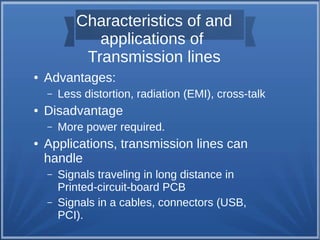
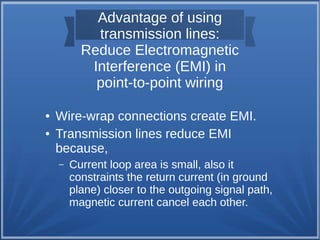
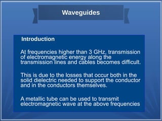
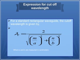
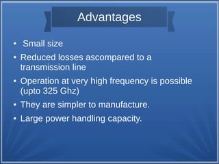
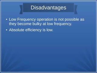
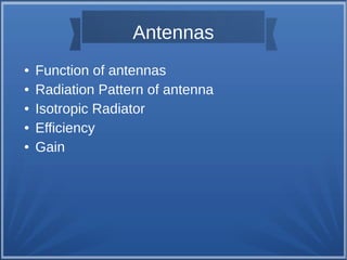
This document provides an overview of basic electronics topics including transmission lines, waveguides, and antenna fundamentals. It discusses the characteristics and applications of transmission lines, advantages of using them to reduce electromagnetic interference, and examples of different types of transmission lines. Waveguides are introduced as an alternative to transmission lines at higher frequencies. Key concepts around waveguides such as applications and the expression for cutoff wavelength are summarized. Finally, the document outlines fundamental concepts relating to antennas such as radiation patterns, efficiency, and gain.


![RF Circuit Design - [Ch4-1] Microwave Transistor Amplifier](https://cdn.slidesharecdn.com/ss_thumbnails/ch4-1-150613064409-lva1-app6892-thumbnail.jpg?width=640&height=640&fit=bounds)