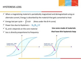
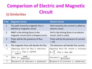
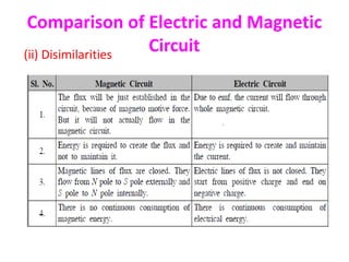
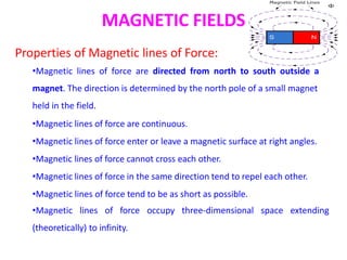
1. The document describes magnetic circuits and electromagnetic induction. It defines key terms related to magnetism such as magnetic flux, magnetic field, hysteresis, reluctance, and permeability.
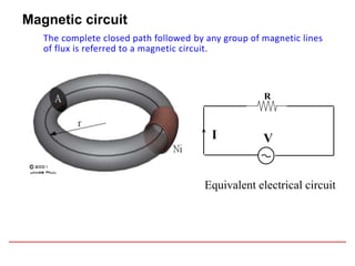
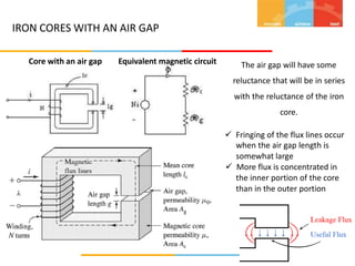
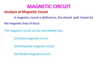
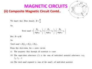
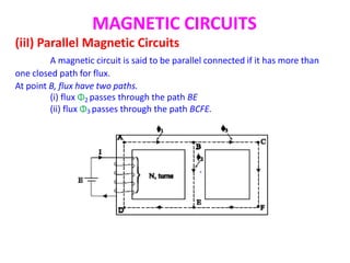
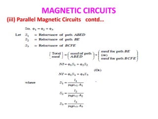
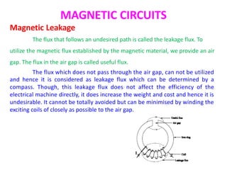
2. The document explains different types of magnetic circuits including simple, composite, and parallel circuits. It also discusses magnetic leakage.
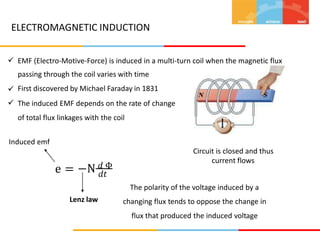
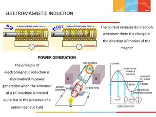
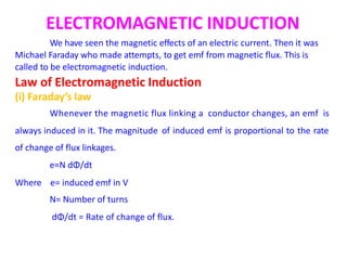
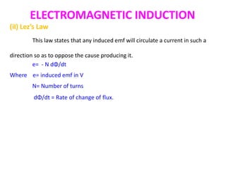
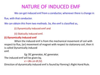
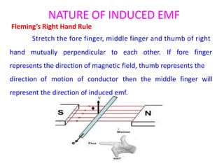
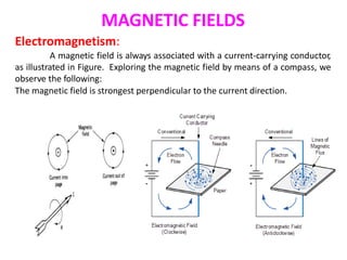
3. Electromagnetic induction is described according to Faraday's law and Lenz's law. Dynamically and statically induced emfs are defined and examples of each are provided.


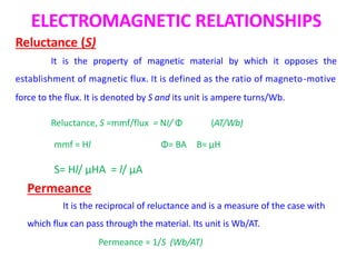
![ELECTROMAGNETIC RELATIONSHIPS
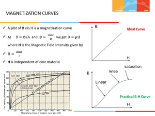
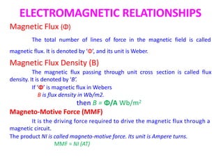
Magnetic field strength: (H)
The magneto motive force per meter length of the magnetic circuit
H = (N I) / L
Unit is AT / meter
Permeability [μ]
A property of a magnetic material which indicates the ability of
magnetic circuit to carry electromagnetic flux.
Ratio of flux density to the magnetizing force,
μ = B / H
Unit: henry / meter
Permeability of free space or air or non magnetic material
μ0=4π*10-7
Relative permeability [μr ]
μ = μ0μr](https://image.slidesharecdn.com/chaptr1magneticcircuits-211029052755/85/magnetic-circuits-11-320.jpg)