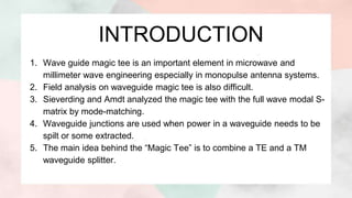
1) The document presents information about a magic tee, which is a waveguide component used in microwave engineering systems.
2) A magic tee has four ports and is able to split or combine signals passing through in specific ways depending on which port is used.
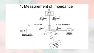
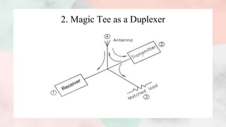
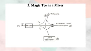
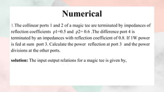
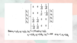
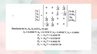
3) The document discusses the working, operation, and S-matrix of a magic tee. It also provides examples of how magic tees can be used for applications like impedance measurement, duplexing, and mixing.


![Putting above values of S parameters in matrix (1), we get,
From unitary property [S][S]*=[I]](https://image.slidesharecdn.com/magictee2-201103172351/85/Magic-tee-8-320.jpg)

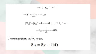

![● Note:-Eq’n (15) and (16) gives that ports 1 and 2 are perfectly matched hence port
3 and port 4 will also match, then such tee is called magic tee.
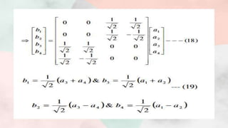
Putting all the values of scattering parameters, we get
We have [b]=[S][a]](https://image.slidesharecdn.com/magictee2-201103172351/85/Magic-tee-12-320.jpg)