

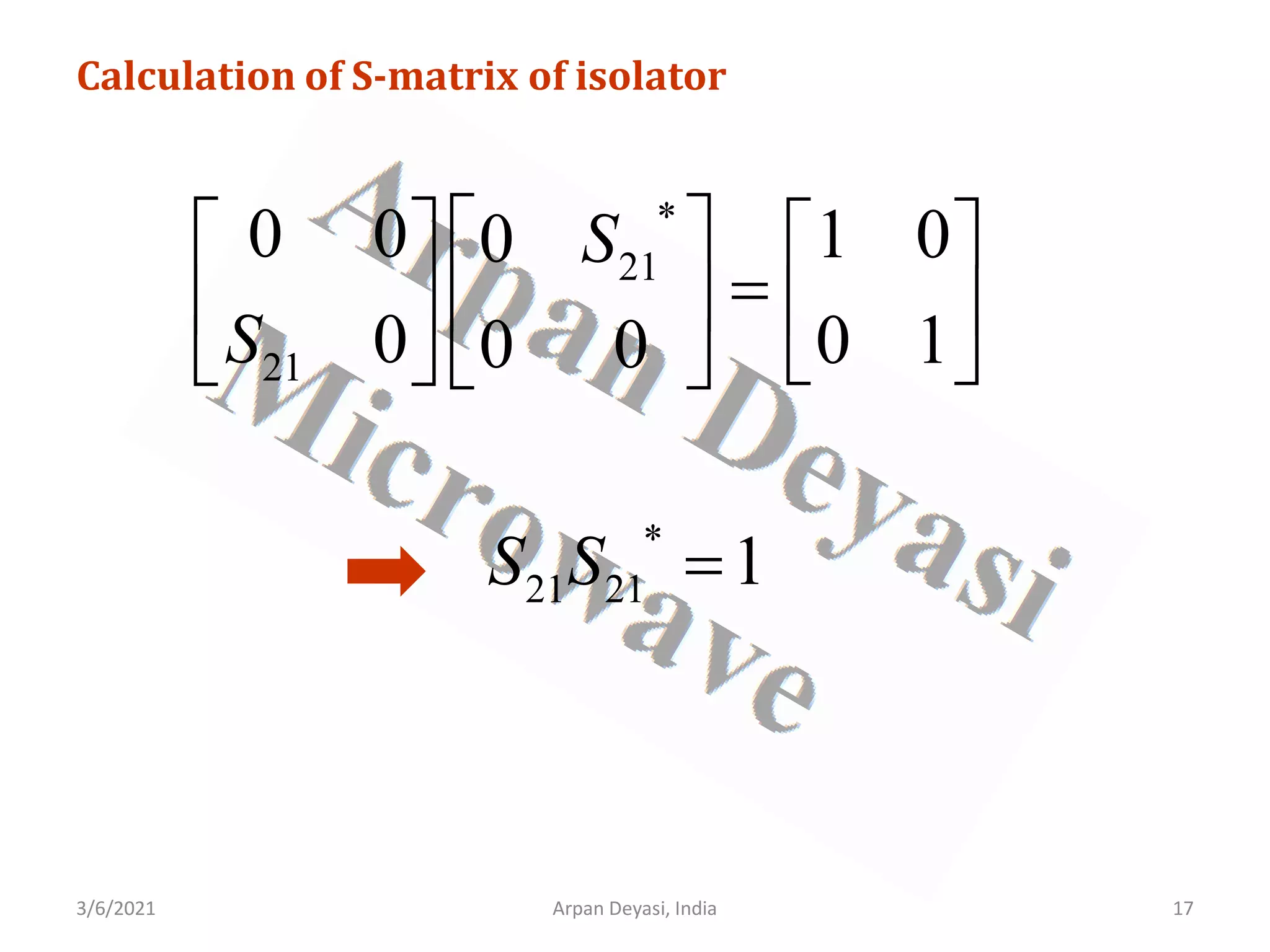
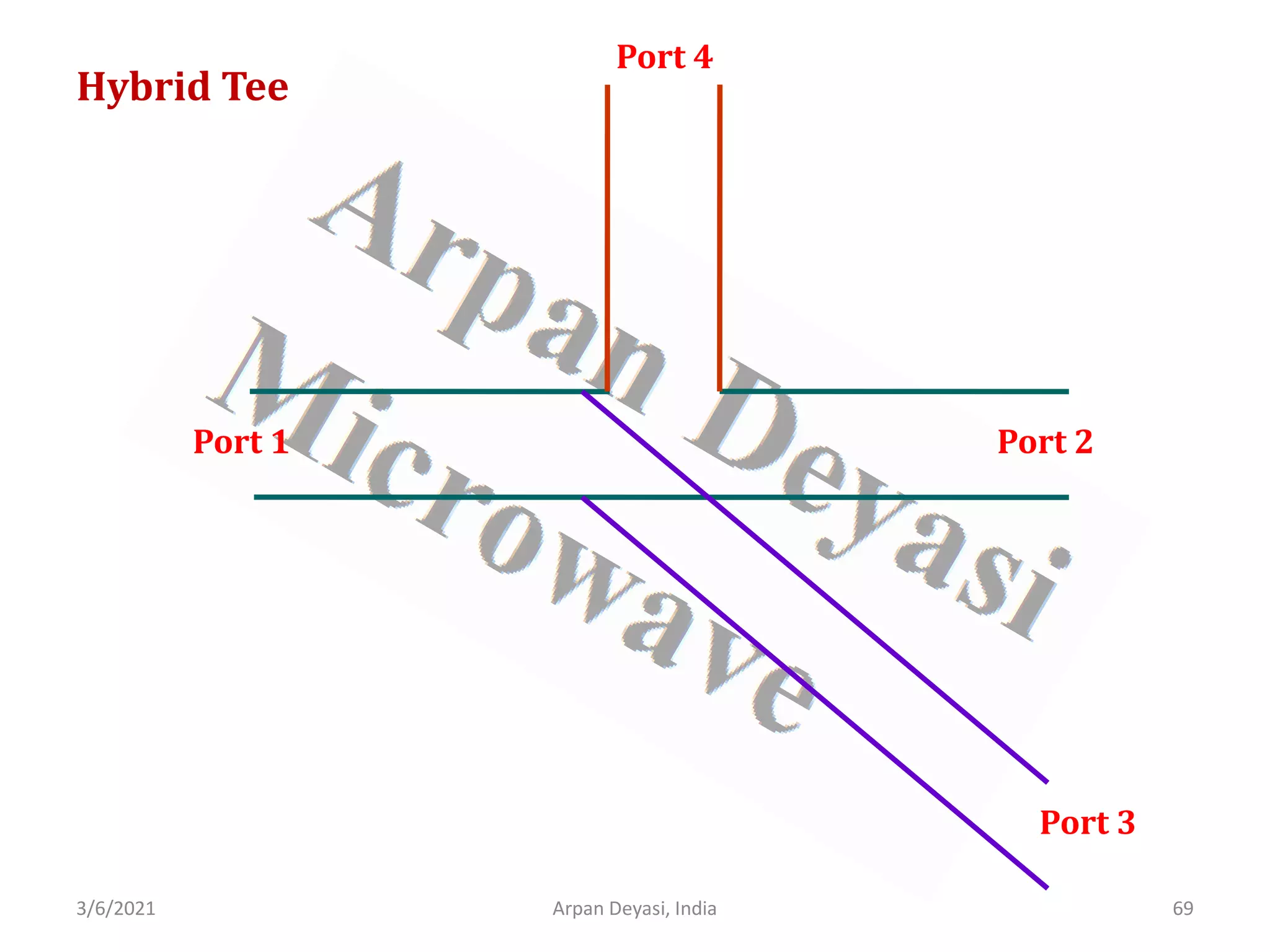
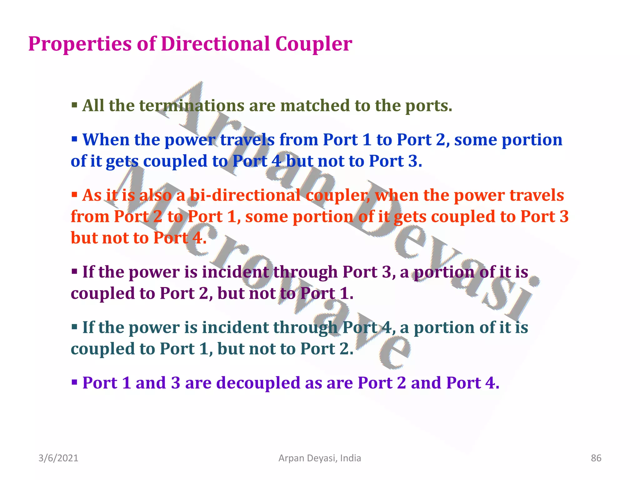
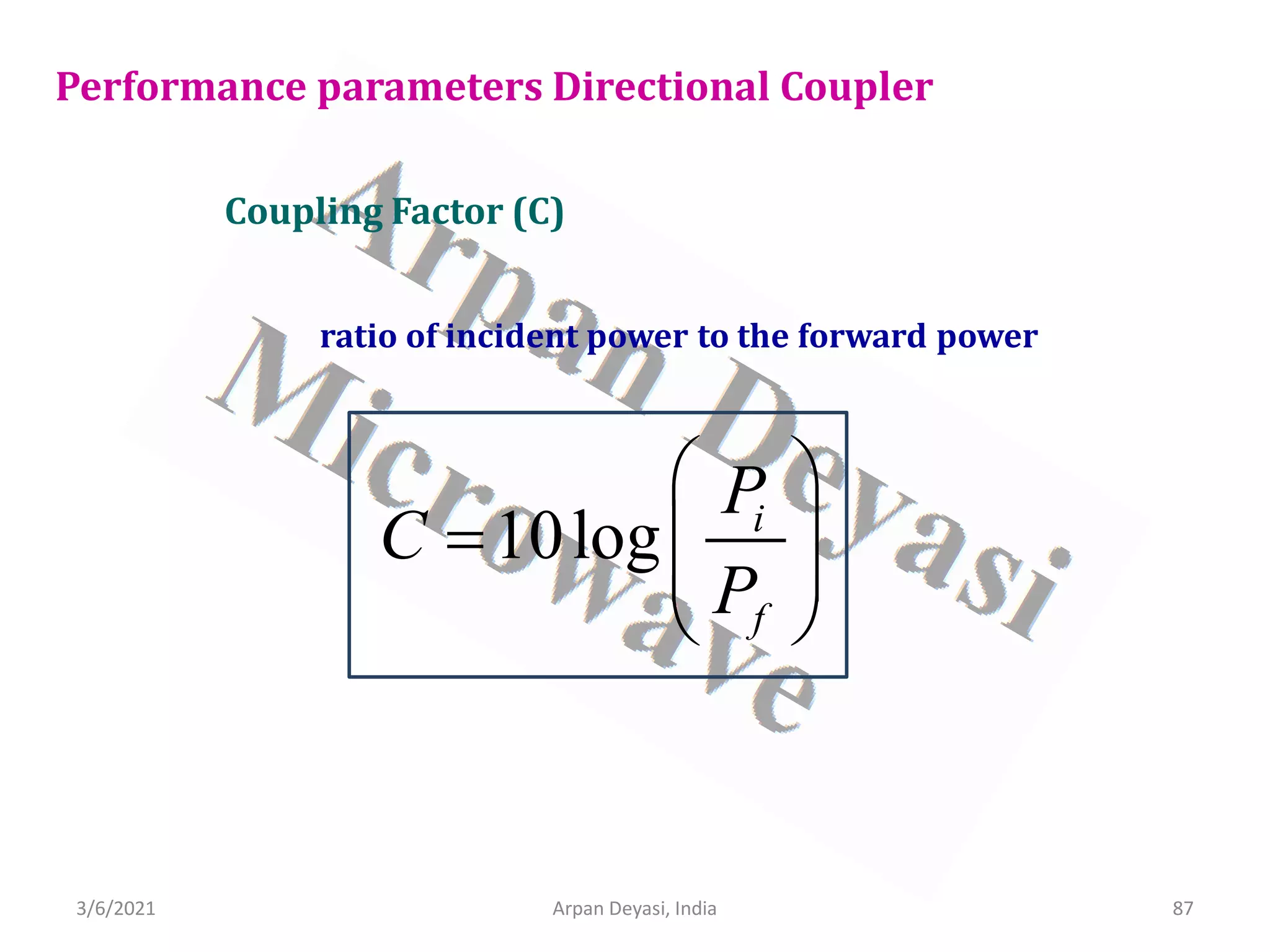
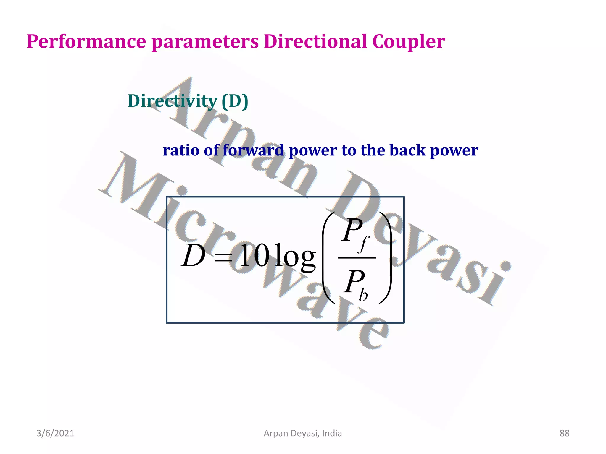
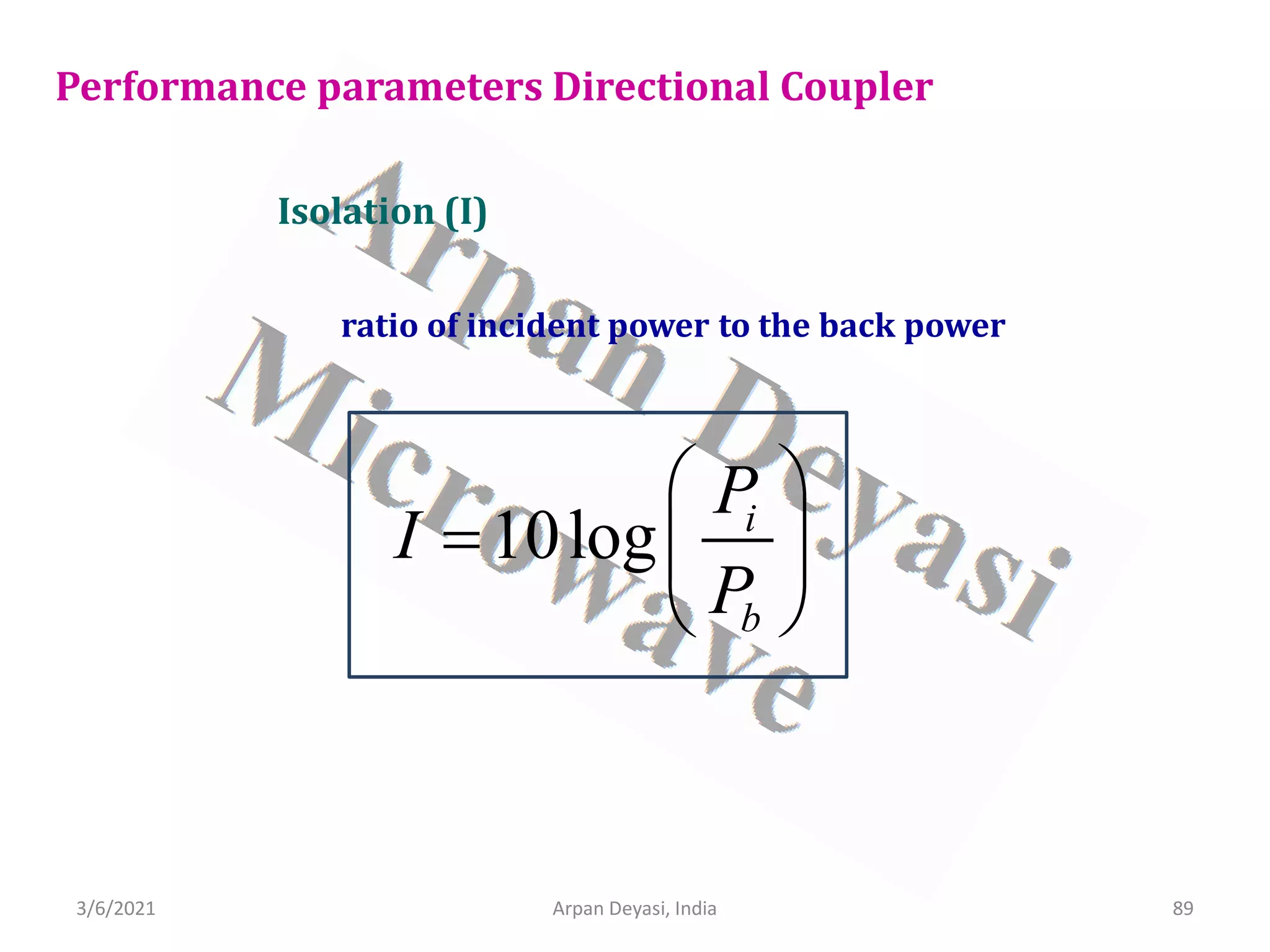
![3/6/2021 5
Arpan Deyasi, India
Calculation of S-matrix of 3-port circulator
General S-matrix of a circulator is
[ ]
11 12 13
21 22 23
31 32 33
S S S
S S S S
S S S
=
](https://image.slidesharecdn.com/waveguidecomponents-210306082708/75/S-matrix-analysis-of-waveguide-components-5-2048.jpg)
![3/6/2021 6
Arpan Deyasi, India
[ ]
11 12 13
21 22 23
31 32 33
S S S
S S S S
S S S
=
Calculation of S-matrix of 3-port circulator
From properties of circulator, all ports are perfectly matched
Diagonal elements become zero
11 22 33 0
S S S
= = =](https://image.slidesharecdn.com/waveguidecomponents-210306082708/75/S-matrix-analysis-of-waveguide-components-6-2048.jpg)
![3/6/2021 Arpan Deyasi, India 7
Calculation of S-matrix of 3-port circulator
For reciprocal ports
[ ]
12 13
21 23
31 32
0
0
0
S S
S S S
S S
=
21 32 13
S S S
= =](https://image.slidesharecdn.com/waveguidecomponents-210306082708/75/S-matrix-analysis-of-waveguide-components-7-2048.jpg)
![3/6/2021 Arpan Deyasi, India 8
Calculation of S-matrix of 3-port circulator
[ ]
12 21
21 23
31 21
0
0
0
S S
S S S
S S
=
Rest of the s-matrix elements are zero
12 23 31 0
S S S
= = =](https://image.slidesharecdn.com/waveguidecomponents-210306082708/75/S-matrix-analysis-of-waveguide-components-8-2048.jpg)
![3/6/2021 Arpan Deyasi, India 9
Calculation of S-matrix of 3-port circulator
[ ]
21
21
21
0 0
0 0
0 0
S
S S
S
=
using Unitary property
[ ][ ]
*
S S I
=](https://image.slidesharecdn.com/waveguidecomponents-210306082708/75/S-matrix-analysis-of-waveguide-components-9-2048.jpg)
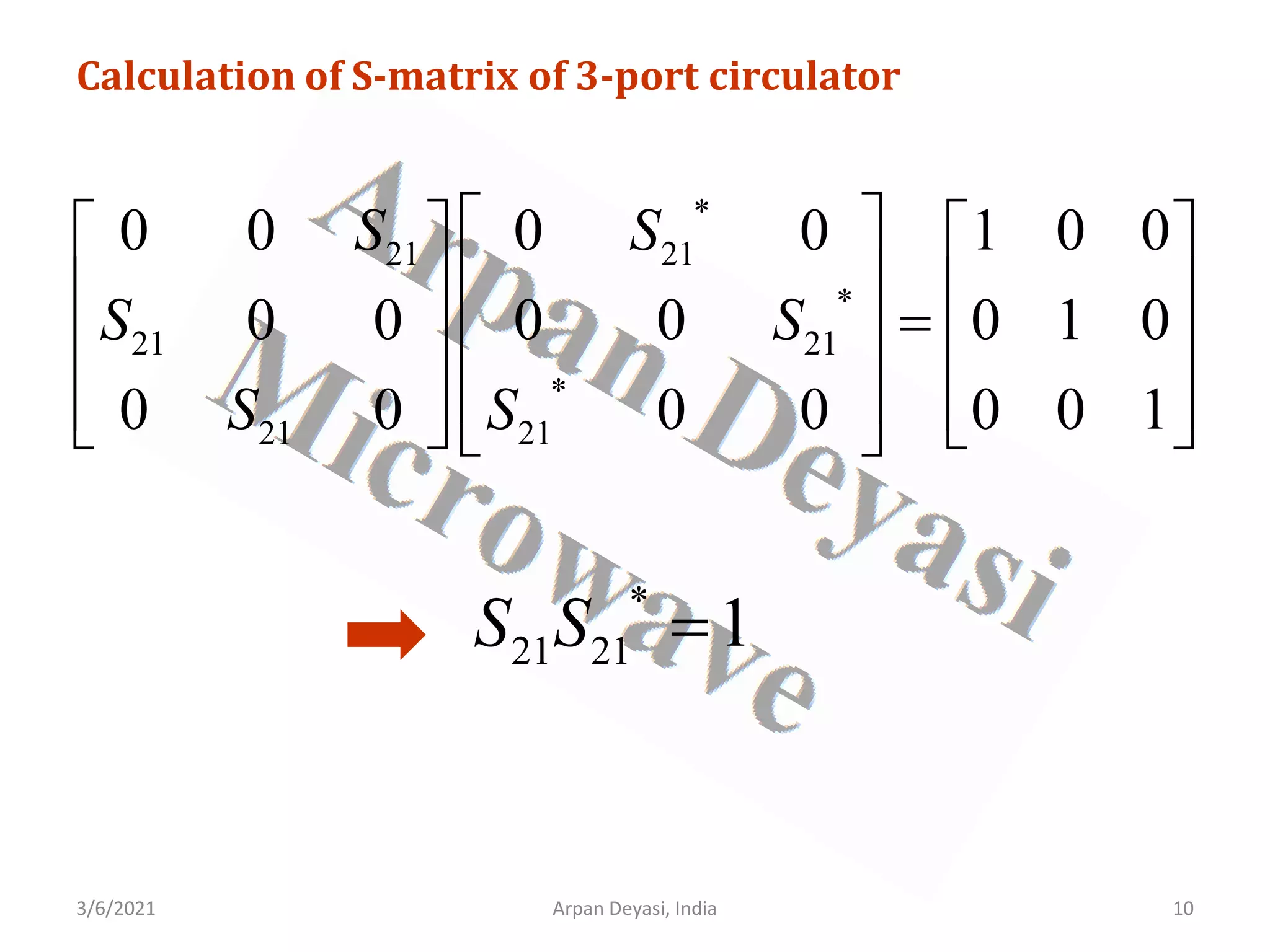
![3/6/2021 Arpan Deyasi, India 11
Calculation of S-matrix of 3-port circulator
2
21 1
S =
Final S-matrix becomes
[ ]
0 0 1
1 0 0
0 1 0
S
=
](https://image.slidesharecdn.com/waveguidecomponents-210306082708/75/S-matrix-analysis-of-waveguide-components-11-2048.jpg)

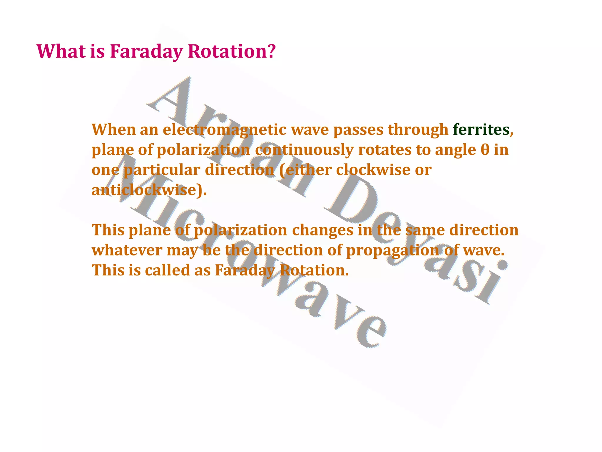
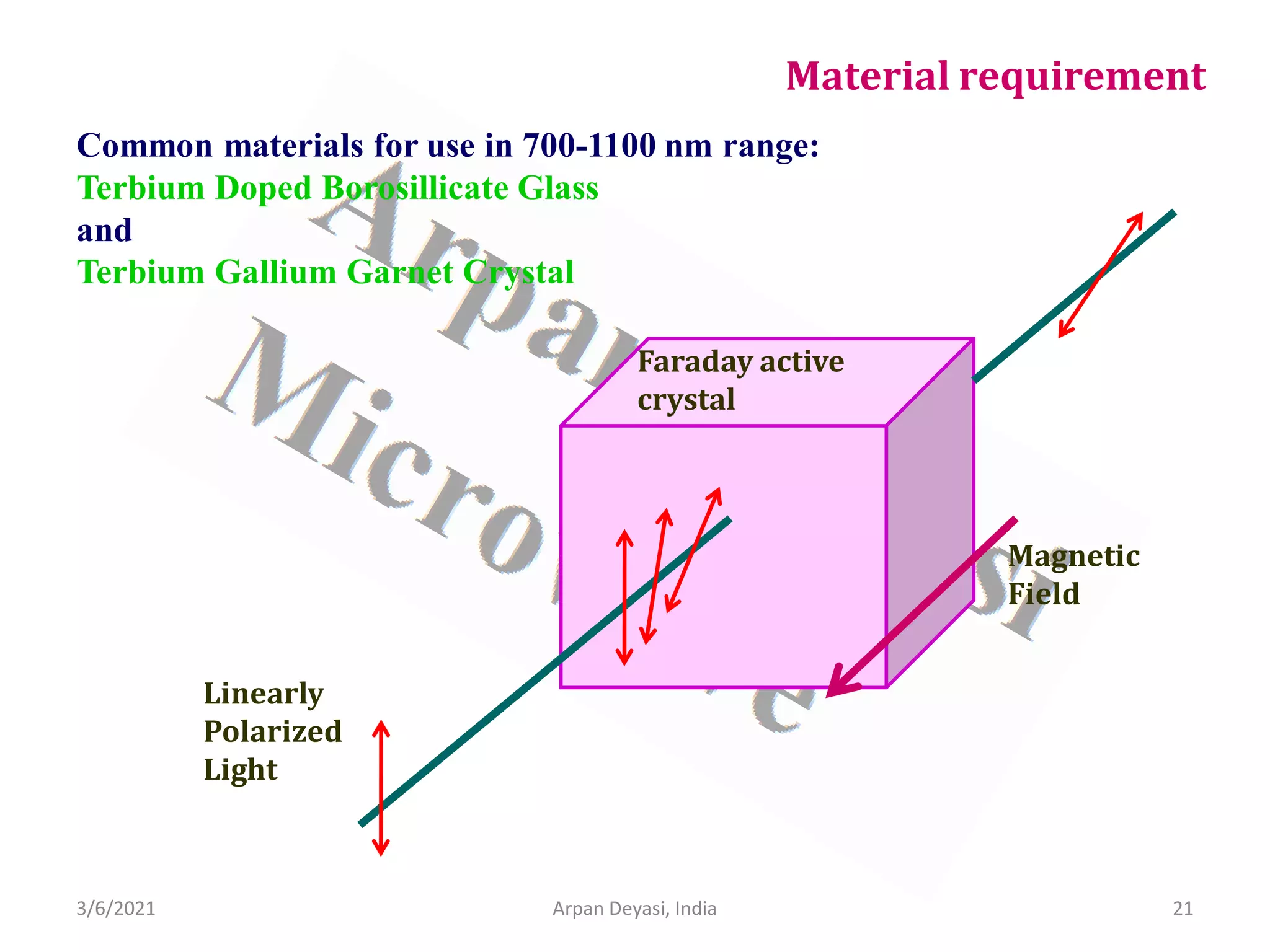
![3/6/2021 Arpan Deyasi, India 14
Calculation of S-matrix of isolator
General S-matrix of an isolator is
[ ] 11 12
21 22
S S
S
S S
=
From properties of isolator, all ports are perfectly matched
11 22 0
S S
= =](https://image.slidesharecdn.com/waveguidecomponents-210306082708/75/S-matrix-analysis-of-waveguide-components-14-2048.jpg)
![3/6/2021 Arpan Deyasi, India 15
Calculation of S-matrix of isolator
[ ] 12
21
0
0
S
S
S
=
From property of isolator
12 0
S =](https://image.slidesharecdn.com/waveguidecomponents-210306082708/75/S-matrix-analysis-of-waveguide-components-15-2048.jpg)
![3/6/2021 16
Arpan Deyasi, India
Calculation of S-matrix of isolator
[ ]
21
0 0
0
S
S
=
using Unitary property
[ ][ ]
*
S S I
=](https://image.slidesharecdn.com/waveguidecomponents-210306082708/75/S-matrix-analysis-of-waveguide-components-16-2048.jpg)
![3/6/2021 18
Arpan Deyasi, India
Calculation of S-matrix of isolator
2
21 1
S =
Final S-matrix becomes
[ ]
0 0
1 0
S
=
](https://image.slidesharecdn.com/waveguidecomponents-210306082708/75/S-matrix-analysis-of-waveguide-components-18-2048.jpg)
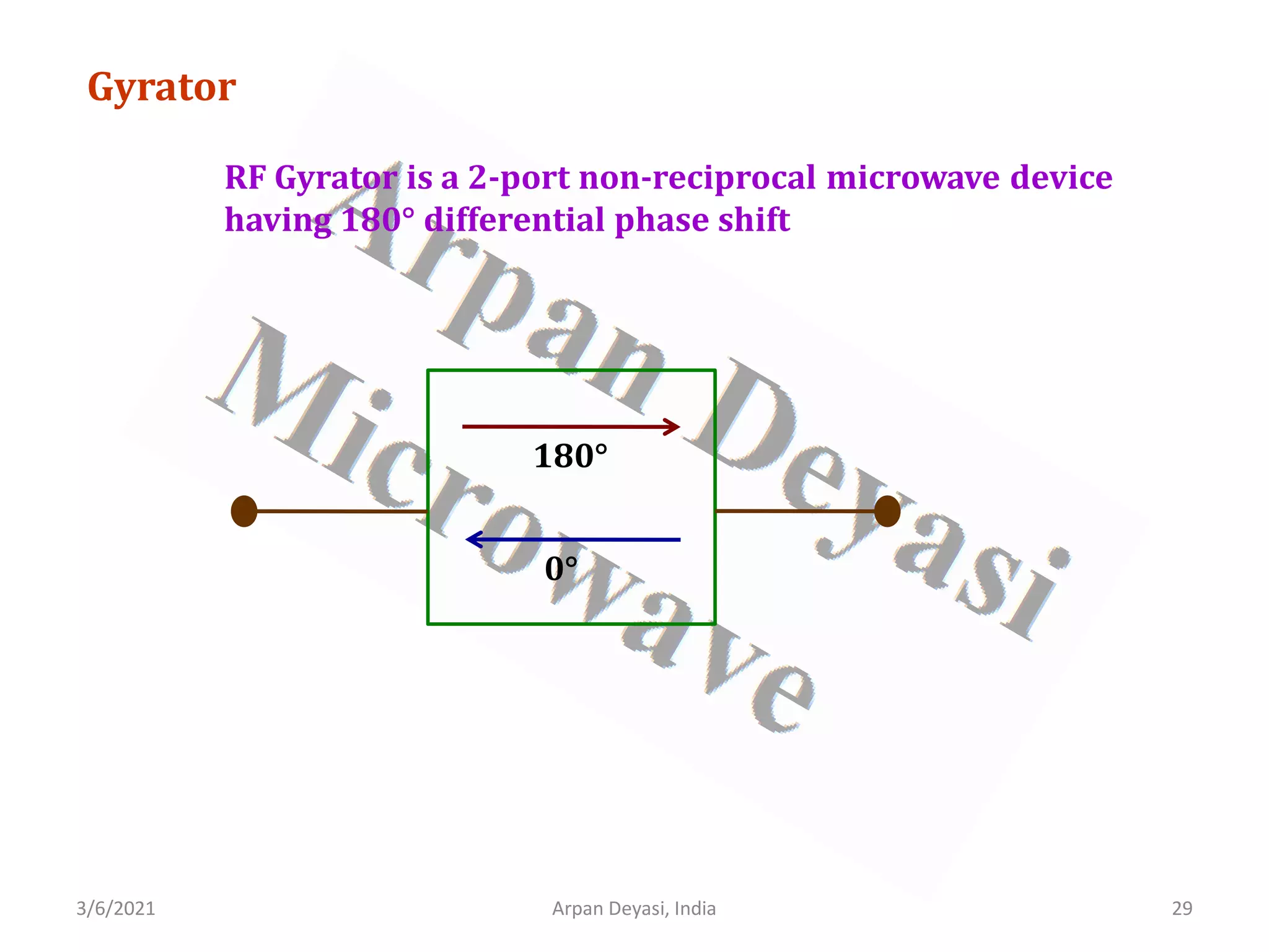
![3/6/2021 Arpan Deyasi, India 30
Calculation of S-matrix of gyrator
General S-matrix of an gyrator is
[ ] 11 12
21 22
S S
S
S S
=
From properties of gyrator, all ports are perfectly matched
11 22 0
S S
= =](https://image.slidesharecdn.com/waveguidecomponents-210306082708/75/S-matrix-analysis-of-waveguide-components-30-2048.jpg)
![3/6/2021 Arpan Deyasi, India 31
Calculation of S-matrix of gyrator
[ ] 12
21
0
0
S
S
S
=
From property of gyrator
12 21
S S
= −](https://image.slidesharecdn.com/waveguidecomponents-210306082708/75/S-matrix-analysis-of-waveguide-components-31-2048.jpg)
![3/6/2021 32
Arpan Deyasi, India
Calculation of S-matrix of gyrator
[ ] 12
12
0
0
S
S
S
=
−
using Unitary property
[ ][ ]
*
S S I
=](https://image.slidesharecdn.com/waveguidecomponents-210306082708/75/S-matrix-analysis-of-waveguide-components-32-2048.jpg)
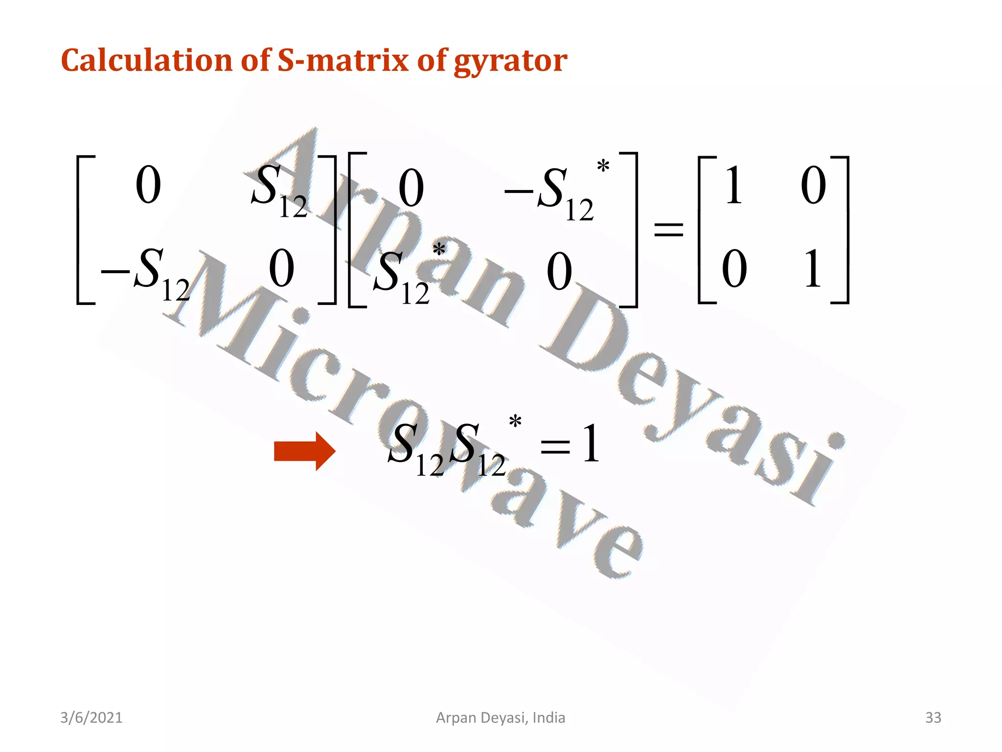
![3/6/2021 34
Arpan Deyasi, India
Calculation of S-matrix of gyrator
2
12 1
S =
Final S-matrix becomes
[ ]
0 1
1 0
S
=
−
](https://image.slidesharecdn.com/waveguidecomponents-210306082708/75/S-matrix-analysis-of-waveguide-components-34-2048.jpg)

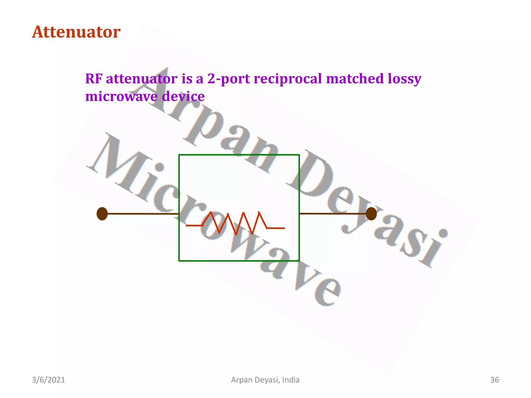
![3/6/2021 37
Arpan Deyasi, India
Calculation of S-matrix of attenuator
General S-matrix of an attenuator is
[ ] 11 12
21 22
S S
S
S S
=
From properties of attenuator, all ports are perfectly matched
11 22 0
S S
= =](https://image.slidesharecdn.com/waveguidecomponents-210306082708/75/S-matrix-analysis-of-waveguide-components-37-2048.jpg)
![3/6/2021 Arpan Deyasi, India 38
Calculation of S-matrix of attenuator
[ ] 12
21
0
0
S
S
S
=
For reciprocal ports
21 12
S S
=](https://image.slidesharecdn.com/waveguidecomponents-210306082708/75/S-matrix-analysis-of-waveguide-components-38-2048.jpg)
![3/6/2021 Arpan Deyasi, India 39
Calculation of S-matrix of attenuator
[ ] 12
12
0
0
S
S
S
=
From property of attenuator
12
S α
=
1
α <](https://image.slidesharecdn.com/waveguidecomponents-210306082708/75/S-matrix-analysis-of-waveguide-components-39-2048.jpg)
![3/6/2021 Arpan Deyasi, India 40
Calculation of S-matrix of attenuator
[ ]
0
0
S
α
α
=
](https://image.slidesharecdn.com/waveguidecomponents-210306082708/75/S-matrix-analysis-of-waveguide-components-40-2048.jpg)


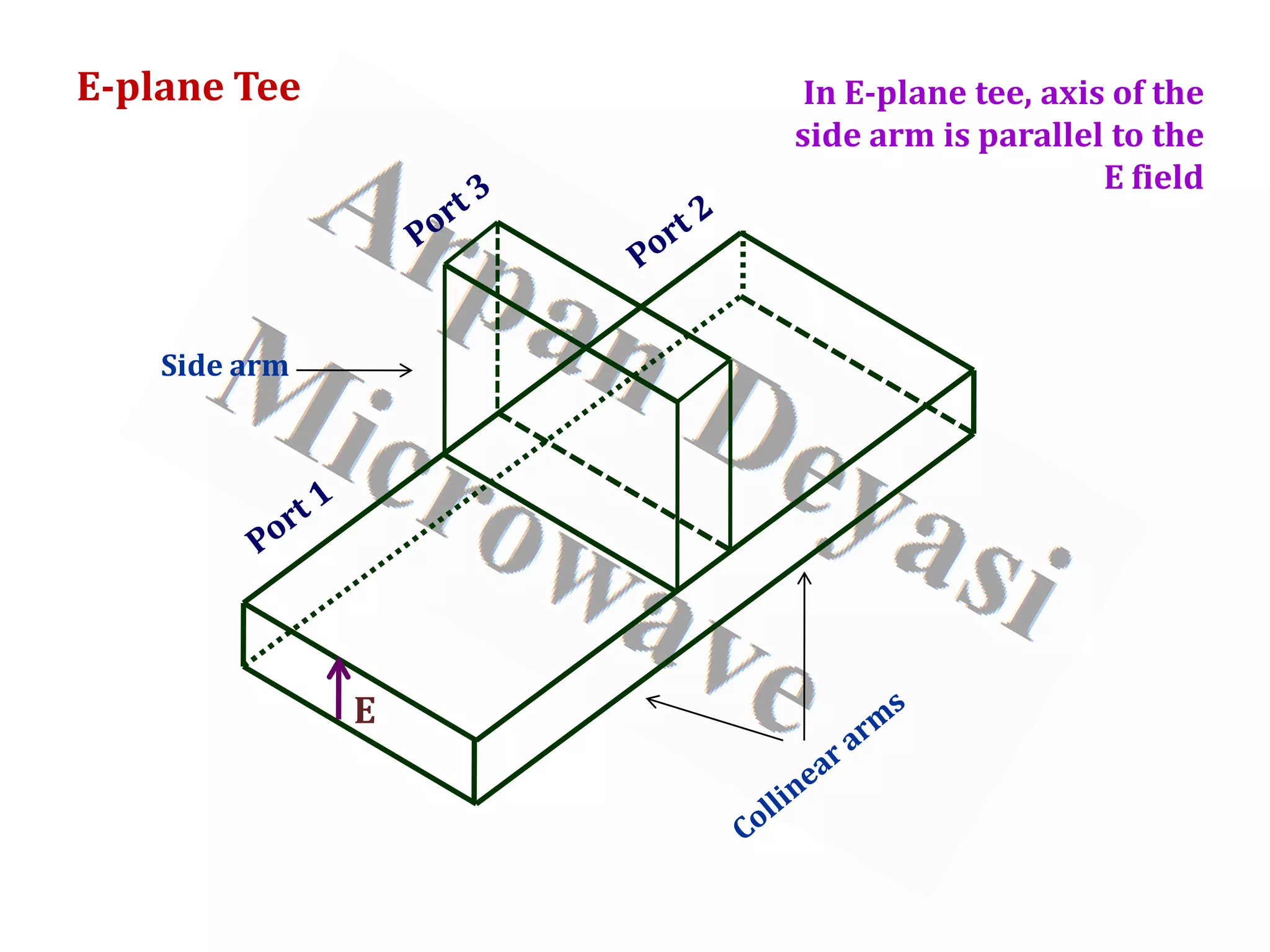
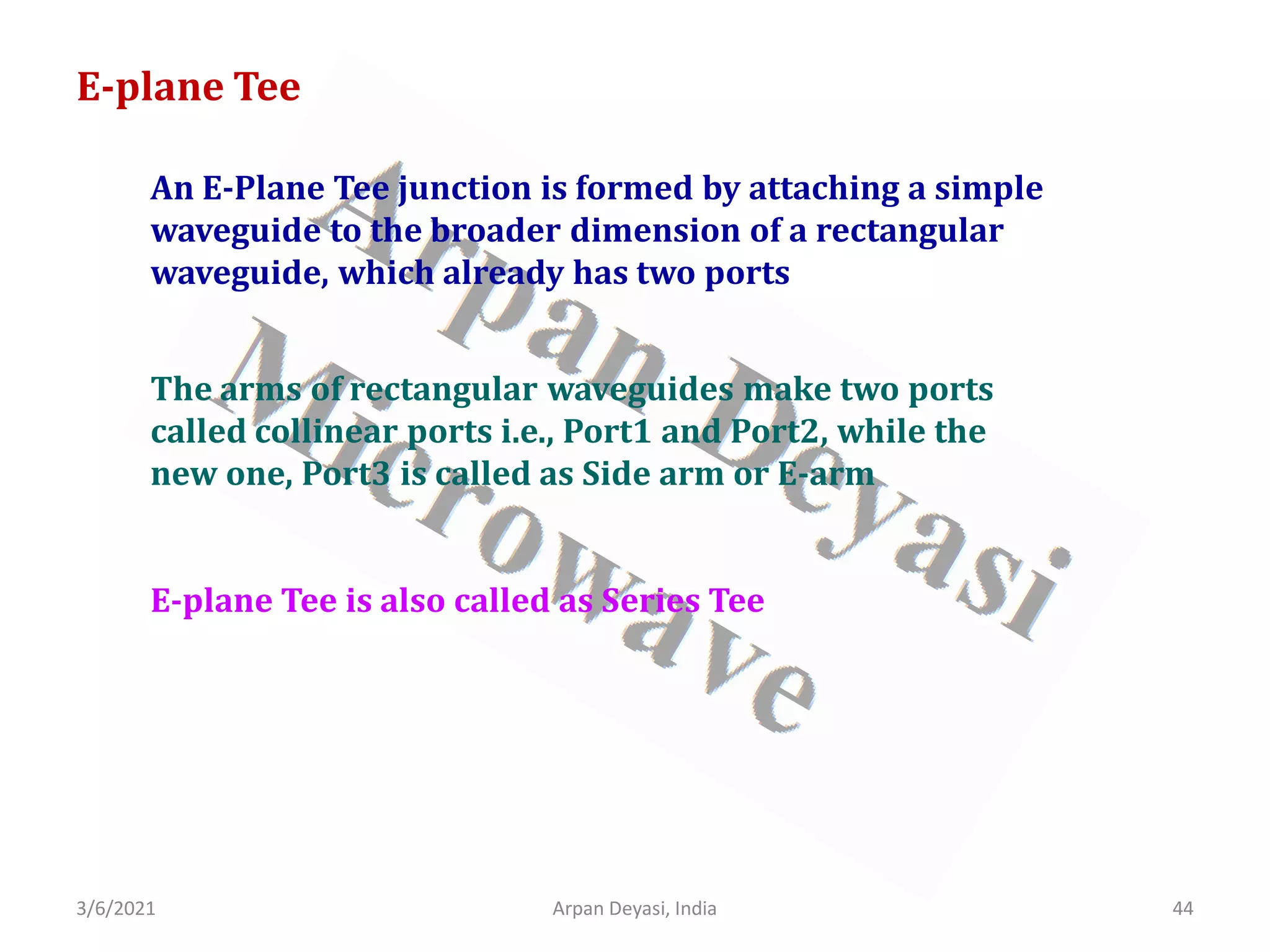
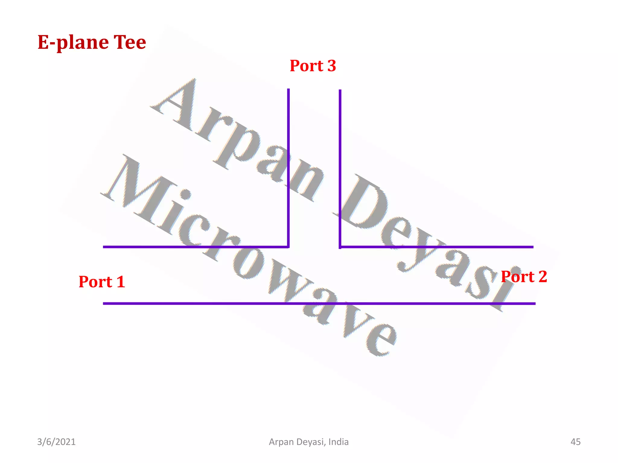
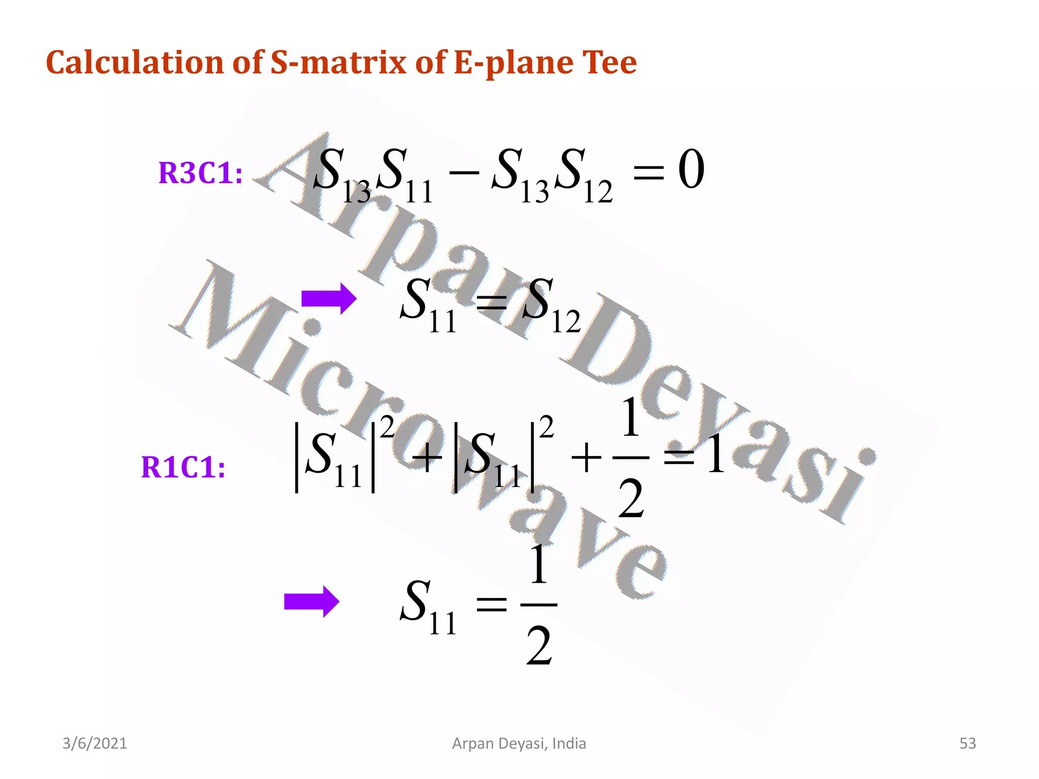
![3/6/2021 Arpan Deyasi, India 46
Calculation of S-matrix of E-plane Tee
General S-matrix of an E-plane Tee is
[ ]
11 12 13
21 22 23
31 32 33
S S S
S S S S
S S S
=
](https://image.slidesharecdn.com/waveguidecomponents-210306082708/75/S-matrix-analysis-of-waveguide-components-46-2048.jpg)
![3/6/2021 Arpan Deyasi, India 47
Calculation of S-matrix of E-plane Tee
With an input at port 3, Scattering coefficients S13 and S23
are out of phase by 180°
[ ]
11 12 13
21 22 13
31 32 33
S S S
S S S S
S S S
= −
13 23
S S
= −](https://image.slidesharecdn.com/waveguidecomponents-210306082708/75/S-matrix-analysis-of-waveguide-components-47-2048.jpg)
![3/6/2021 Arpan Deyasi, India 48
Calculation of S-matrix of E-plane Tee
port 3 is perfectly matched
33 0
S =
[ ]
11 12 13
21 22 13
31 32 0
S S S
S S S S
S S
= −
](https://image.slidesharecdn.com/waveguidecomponents-210306082708/75/S-matrix-analysis-of-waveguide-components-48-2048.jpg)
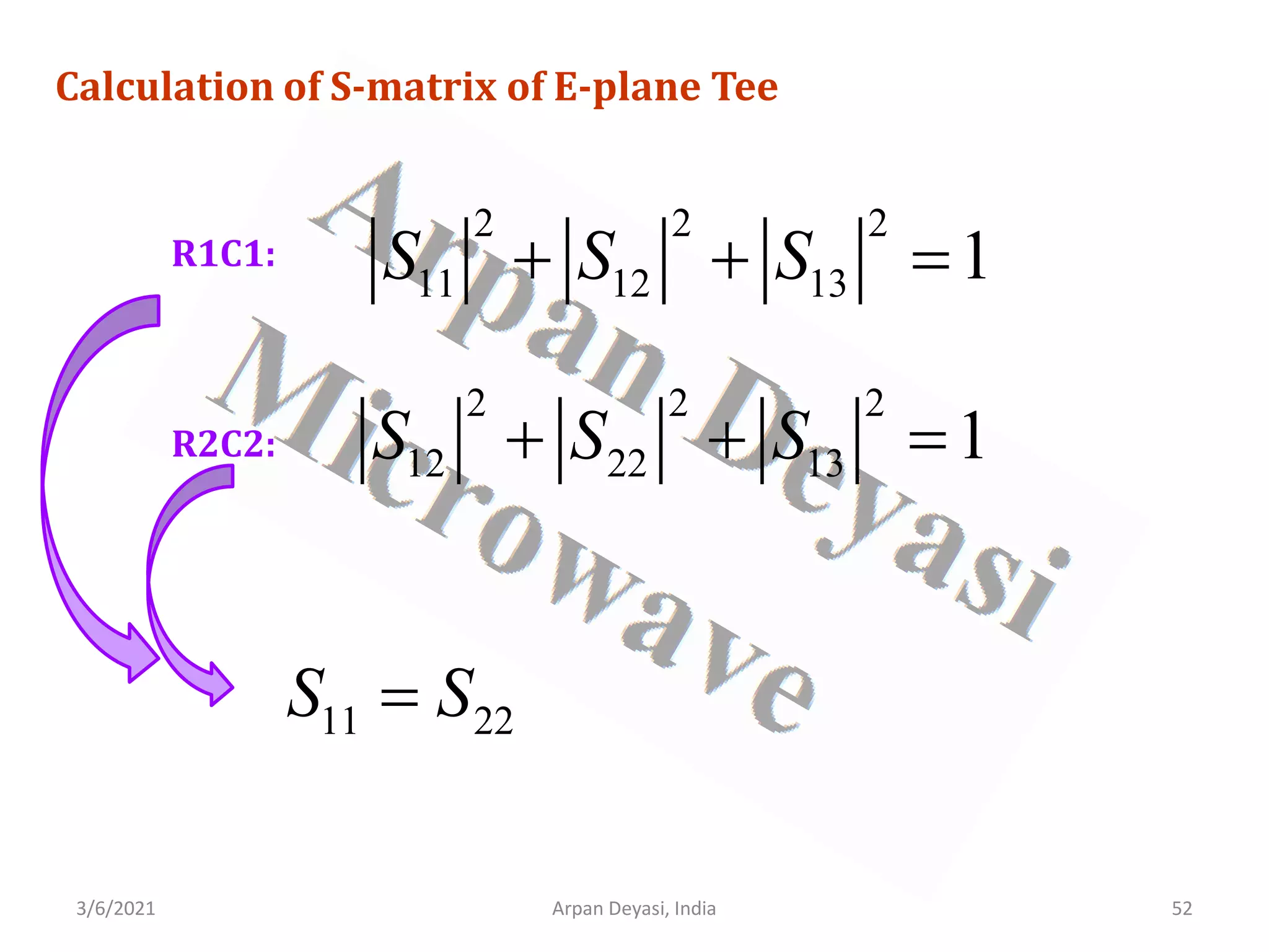
![3/6/2021 Arpan Deyasi, India 49
Calculation of S-matrix of E-plane Tee
From symmetry property
12 21
S S
= 23 32
S S
= 13 31
S S
=
[ ]
11 12 13
12 22 13
13 13 0
S S S
S S S S
S S
= −
−
](https://image.slidesharecdn.com/waveguidecomponents-210306082708/75/S-matrix-analysis-of-waveguide-components-49-2048.jpg)
![3/6/2021 Arpan Deyasi, India 50
Calculation of S-matrix of E-plane Tee
using Unitary property
[ ][ ]
*
S S I
=
* * *
11 12 13 11 12 13
* * *
12 22 13 12 22 13
* *
13 13 13 13
1 0 0
0 1 0
0 0 0 0 1
S S S S S S
S S S S S S
S S S S
− − =
− −
](https://image.slidesharecdn.com/waveguidecomponents-210306082708/75/S-matrix-analysis-of-waveguide-components-50-2048.jpg)
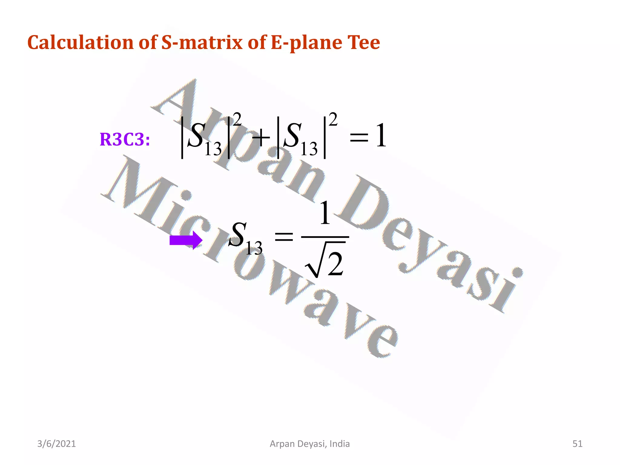
![3/6/2021 Arpan Deyasi, India 54
Calculation of S-matrix of E-plane Tee
[ ]
1 1 1
2 2 2
1 1 1
2 2 2
1 1
0
2 2
S
−
−
](https://image.slidesharecdn.com/waveguidecomponents-210306082708/75/S-matrix-analysis-of-waveguide-components-54-2048.jpg)
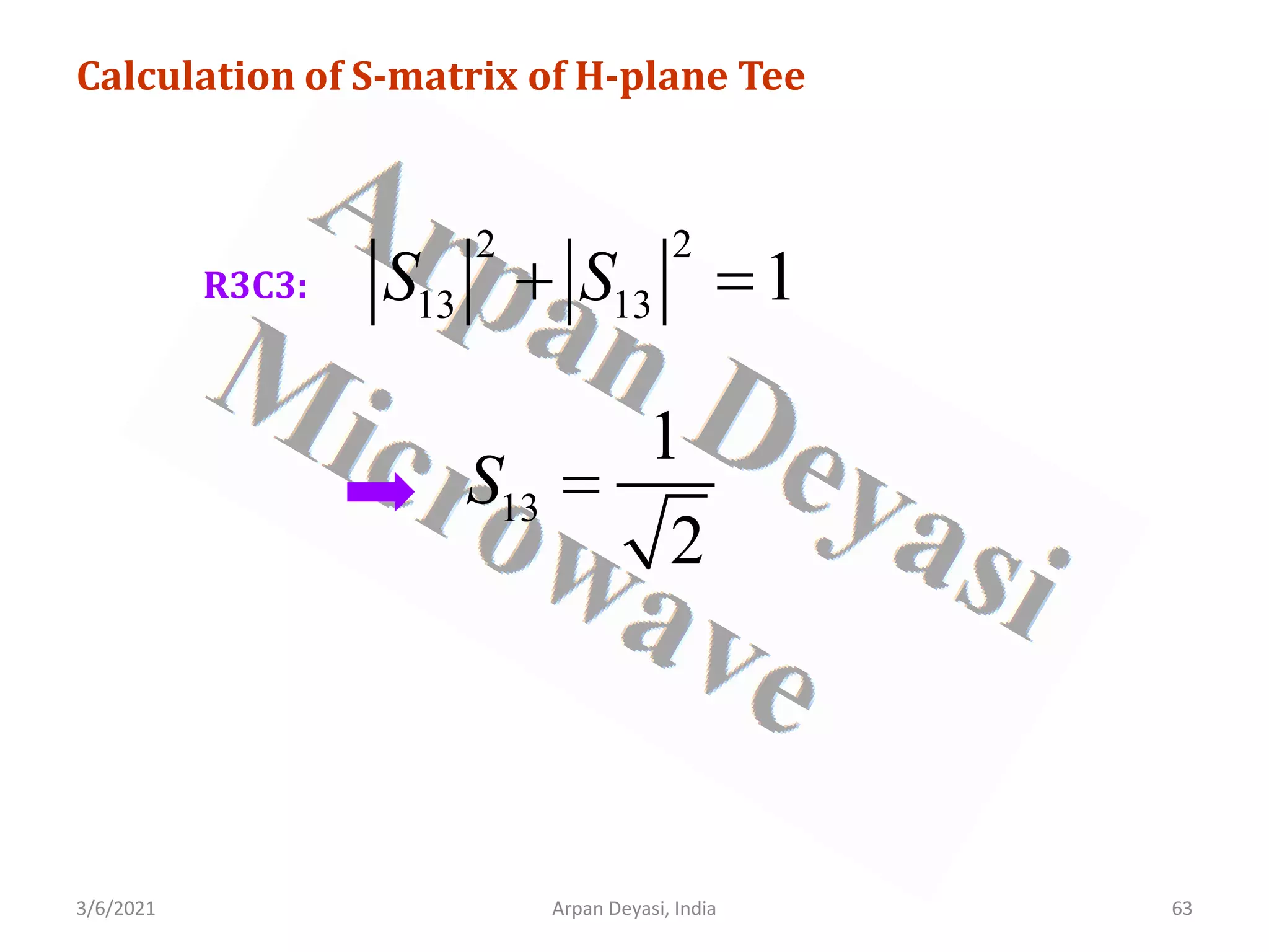
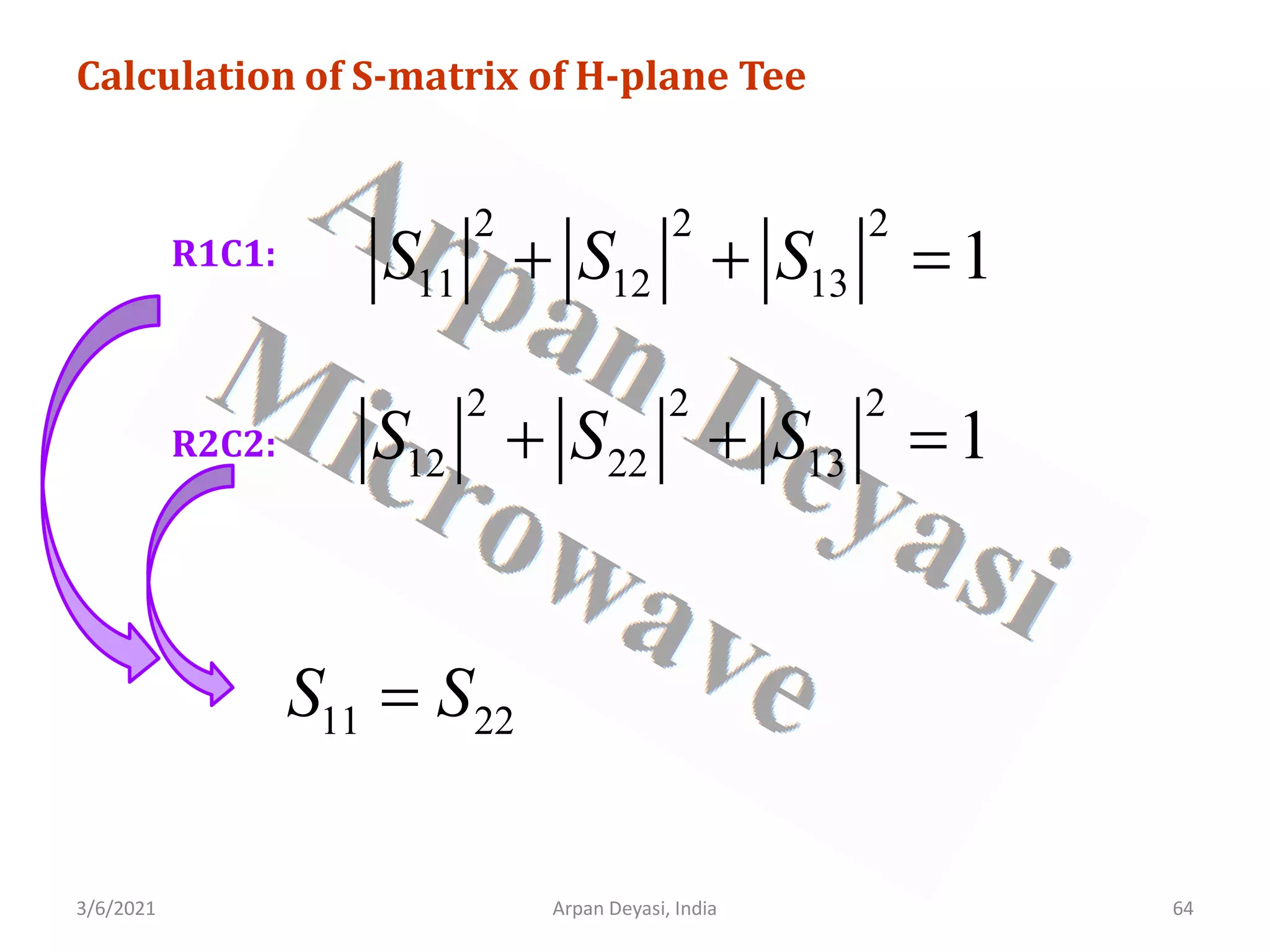
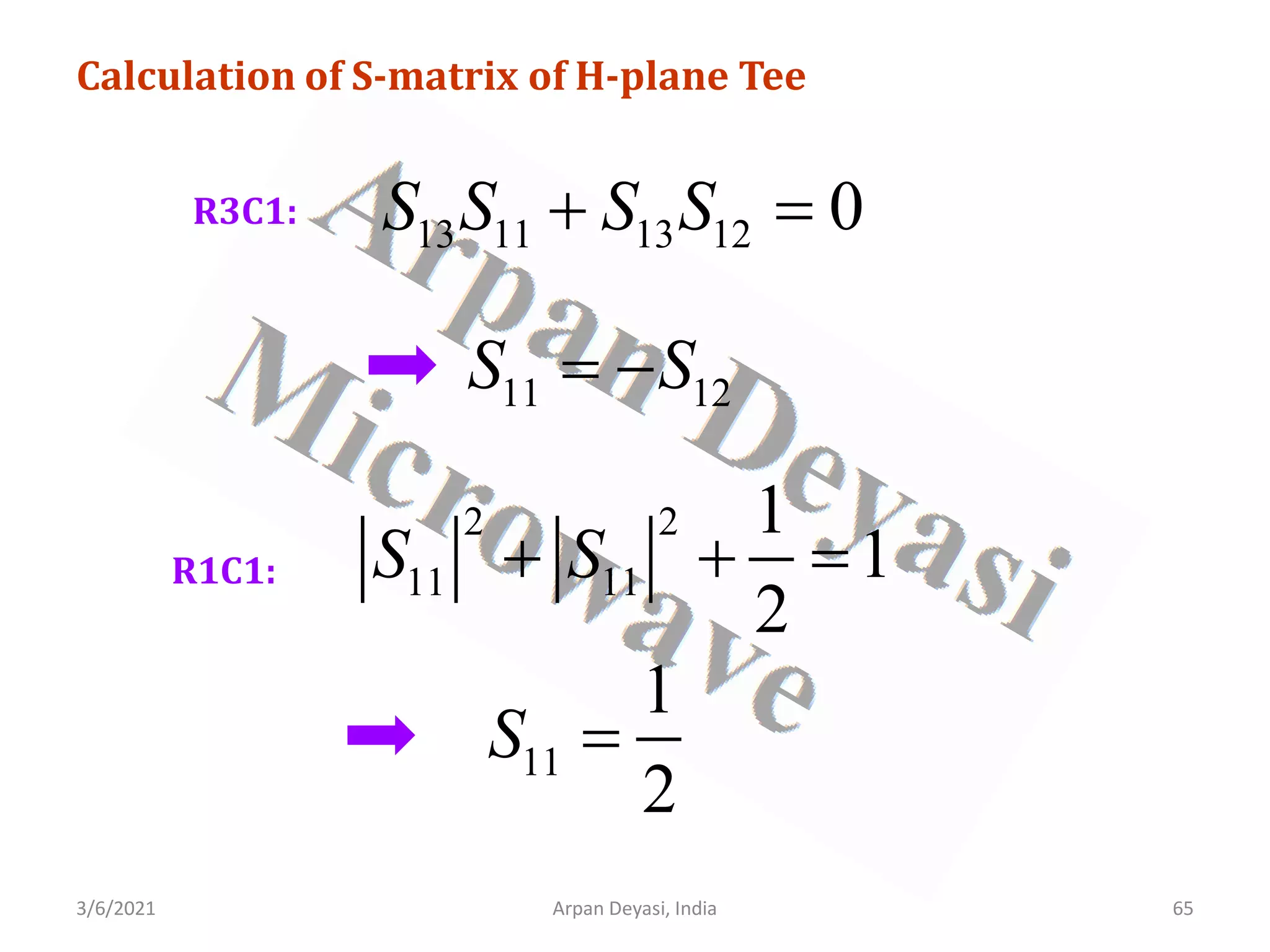
![3/6/2021 Arpan Deyasi, India 58
Calculation of S-matrix of H-plane Tee
General S-matrix of an H-plane Tee is
[ ]
11 12 13
21 22 23
31 32 33
S S S
S S S S
S S S
=
](https://image.slidesharecdn.com/waveguidecomponents-210306082708/75/S-matrix-analysis-of-waveguide-components-58-2048.jpg)
![3/6/2021 Arpan Deyasi, India 59
Calculation of S-matrix of H-plane Tee
With an input at port 3, Scattering coefficients S13 and S23
are perfectly matched
[ ]
11 12 13
21 22 13
31 32 33
S S S
S S S S
S S S
=
13 23
S S
=](https://image.slidesharecdn.com/waveguidecomponents-210306082708/75/S-matrix-analysis-of-waveguide-components-59-2048.jpg)
![3/6/2021 Arpan Deyasi, India 60
Calculation of S-matrix of H-plane Tee
port 3 is perfectly matched
33 0
S =
[ ]
11 12 13
21 22 13
31 32 0
S S S
S S S S
S S
=
](https://image.slidesharecdn.com/waveguidecomponents-210306082708/75/S-matrix-analysis-of-waveguide-components-60-2048.jpg)
![3/6/2021 Arpan Deyasi, India 61
Calculation of S-matrix of H-plane Tee
From symmetry property
12 21
S S
= 23 32
S S
= 13 31
S S
=
[ ]
11 12 13
12 22 13
13 13 0
S S S
S S S S
S S
=
](https://image.slidesharecdn.com/waveguidecomponents-210306082708/75/S-matrix-analysis-of-waveguide-components-61-2048.jpg)
![3/6/2021 Arpan Deyasi, India 62
Calculation of S-matrix of H-plane Tee
using Unitary property
[ ][ ]
*
S S I
=
* * *
11 12 13 11 12 13
* * *
12 22 13 12 22 13
* *
13 13 13 13
1 0 0
0 1 0
0 0 0 0 1
S S S S S S
S S S S S S
S S S S
=
](https://image.slidesharecdn.com/waveguidecomponents-210306082708/75/S-matrix-analysis-of-waveguide-components-62-2048.jpg)
![3/6/2021 Arpan Deyasi, India 66
Calculation of S-matrix of H-plane Tee
[ ]
1 1 1
2 2 2
1 1 1
2 2 2
1 1
0
2 2
S
−
= −
](https://image.slidesharecdn.com/waveguidecomponents-210306082708/75/S-matrix-analysis-of-waveguide-components-66-2048.jpg)
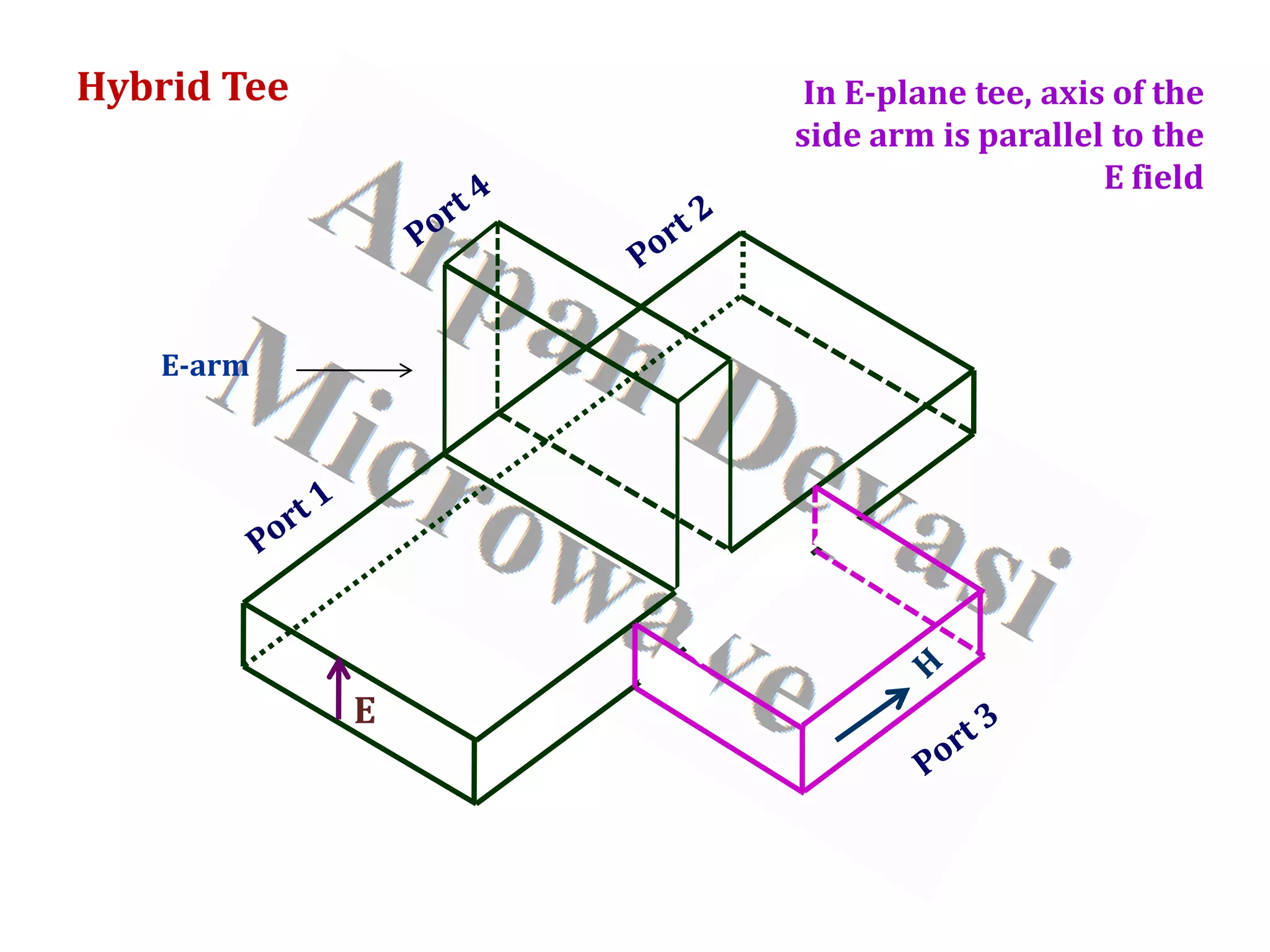
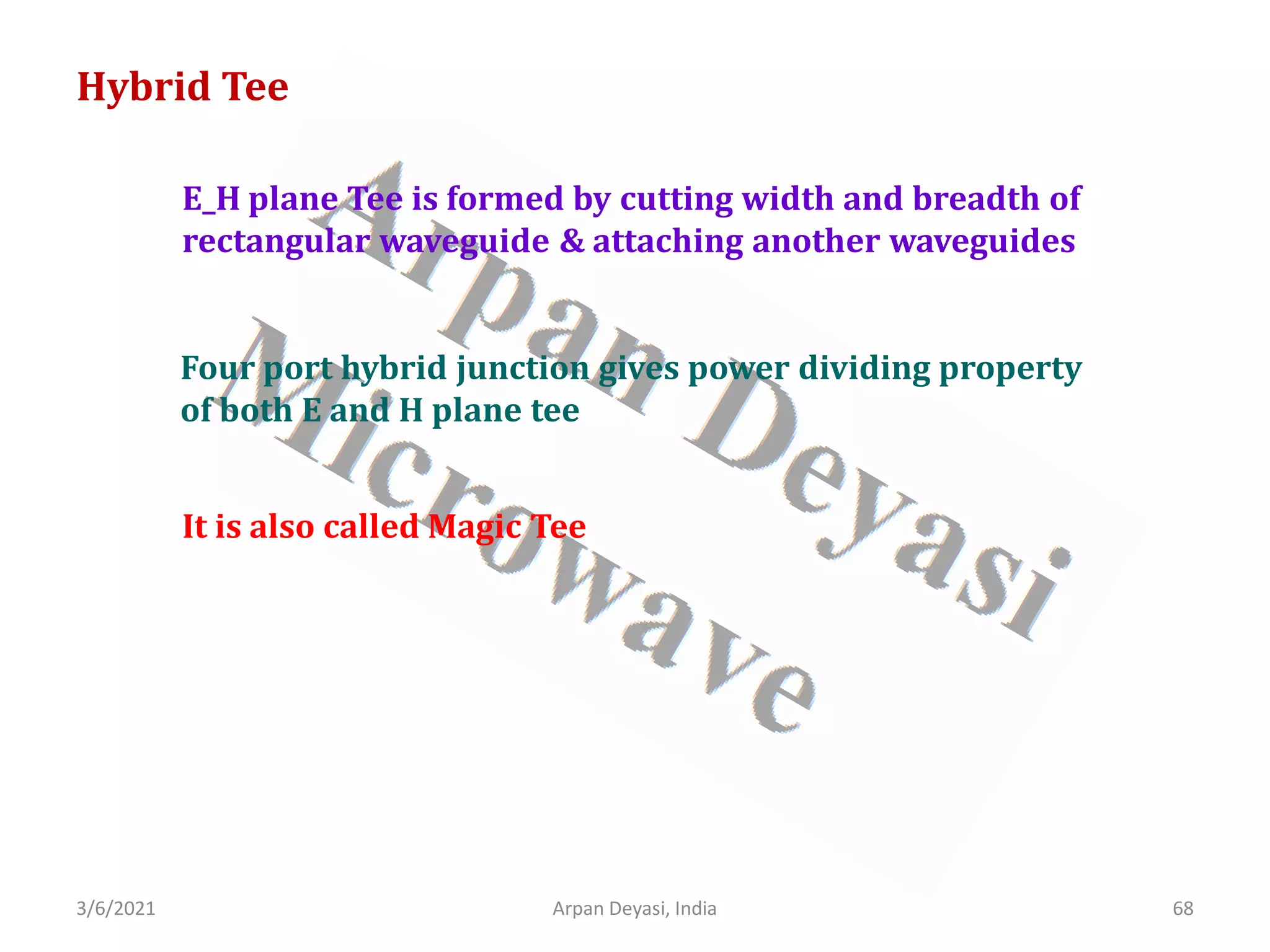
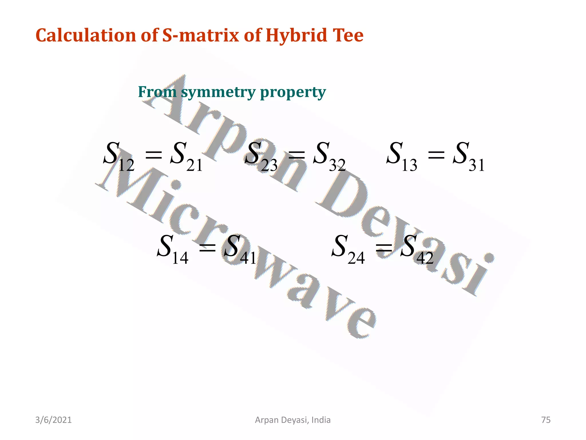
![3/6/2021 Arpan Deyasi, India 70
Calculation of S-matrix of Hybrid Tee
General S-matrix of an Hybrid Tee is
[ ]
11 12 13 14
21 22 23 24
31 32 33 34
41 42 43 44
S S S S
S S S S
S
S S S S
S S S S
=
](https://image.slidesharecdn.com/waveguidecomponents-210306082708/75/S-matrix-analysis-of-waveguide-components-70-2048.jpg)
![3/6/2021 Arpan Deyasi, India 71
Calculation of S-matrix of Hybrid Tee
Because of H-plane tee junction
13 23
S S
=
[ ]
11 12 13 14
21 22 13 24
31 32 33 34
41 42 43 44
S S S S
S S S S
S
S S S S
S S S S
=
](https://image.slidesharecdn.com/waveguidecomponents-210306082708/75/S-matrix-analysis-of-waveguide-components-71-2048.jpg)
![3/6/2021 Arpan Deyasi, India 72
Calculation of S-matrix of Hybrid Tee
Because of E-plane tee junction
14 24
S S
= −
[ ]
11 12 13 14
21 22 13 14
31 32 33 34
41 42 43 44
S S S S
S S S S
S
S S S S
S S S S
−
=
](https://image.slidesharecdn.com/waveguidecomponents-210306082708/75/S-matrix-analysis-of-waveguide-components-72-2048.jpg)
![3/6/2021 Arpan Deyasi, India 73
Calculation of S-matrix of Hybrid Tee
Because of geometry of junctions, port 3 and port 4 are isolated
34 43 0
S S
= =
[ ]
11 12 13 14
21 22 13 14
31 32 33
41 42 44
0
0
S S S S
S S S S
S
S S S
S S S
−
=
](https://image.slidesharecdn.com/waveguidecomponents-210306082708/75/S-matrix-analysis-of-waveguide-components-73-2048.jpg)
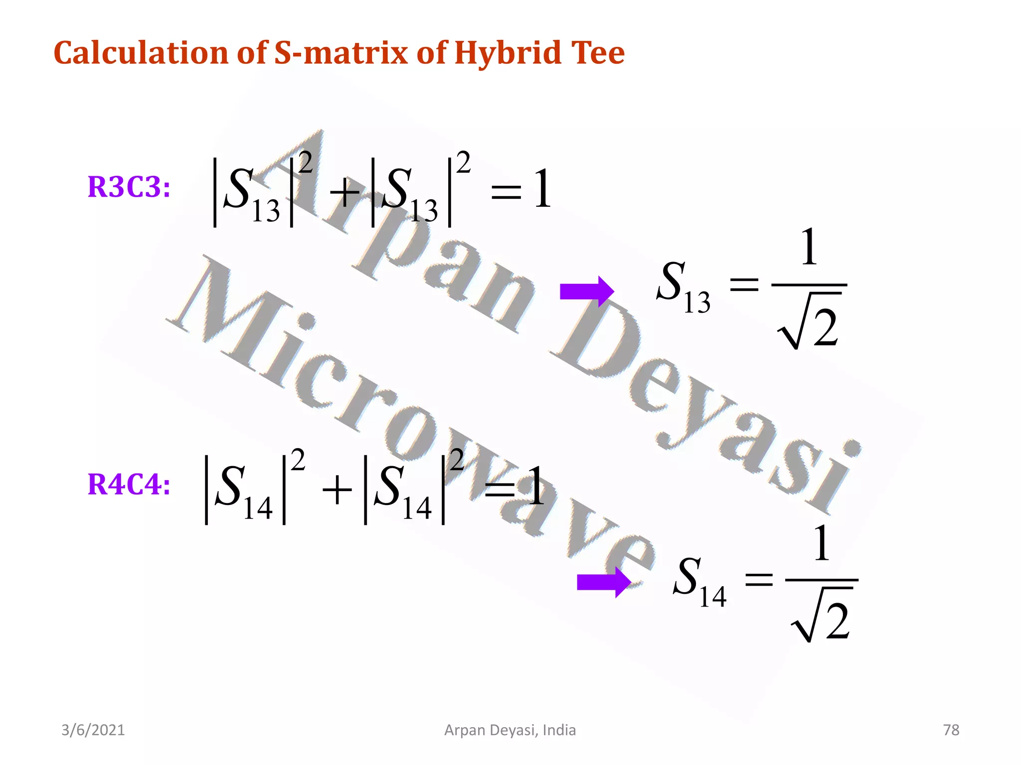
![3/6/2021 Arpan Deyasi, India 74
Calculation of S-matrix of Hybrid Tee
port 3 and port 4 are perfectly matched
33 44 0
S S
= =
[ ]
11 12 13 14
21 22 13 14
31 32
41 42
0 0
0 0
S S S S
S S S S
S
S S
S S
−
=
](https://image.slidesharecdn.com/waveguidecomponents-210306082708/75/S-matrix-analysis-of-waveguide-components-74-2048.jpg)
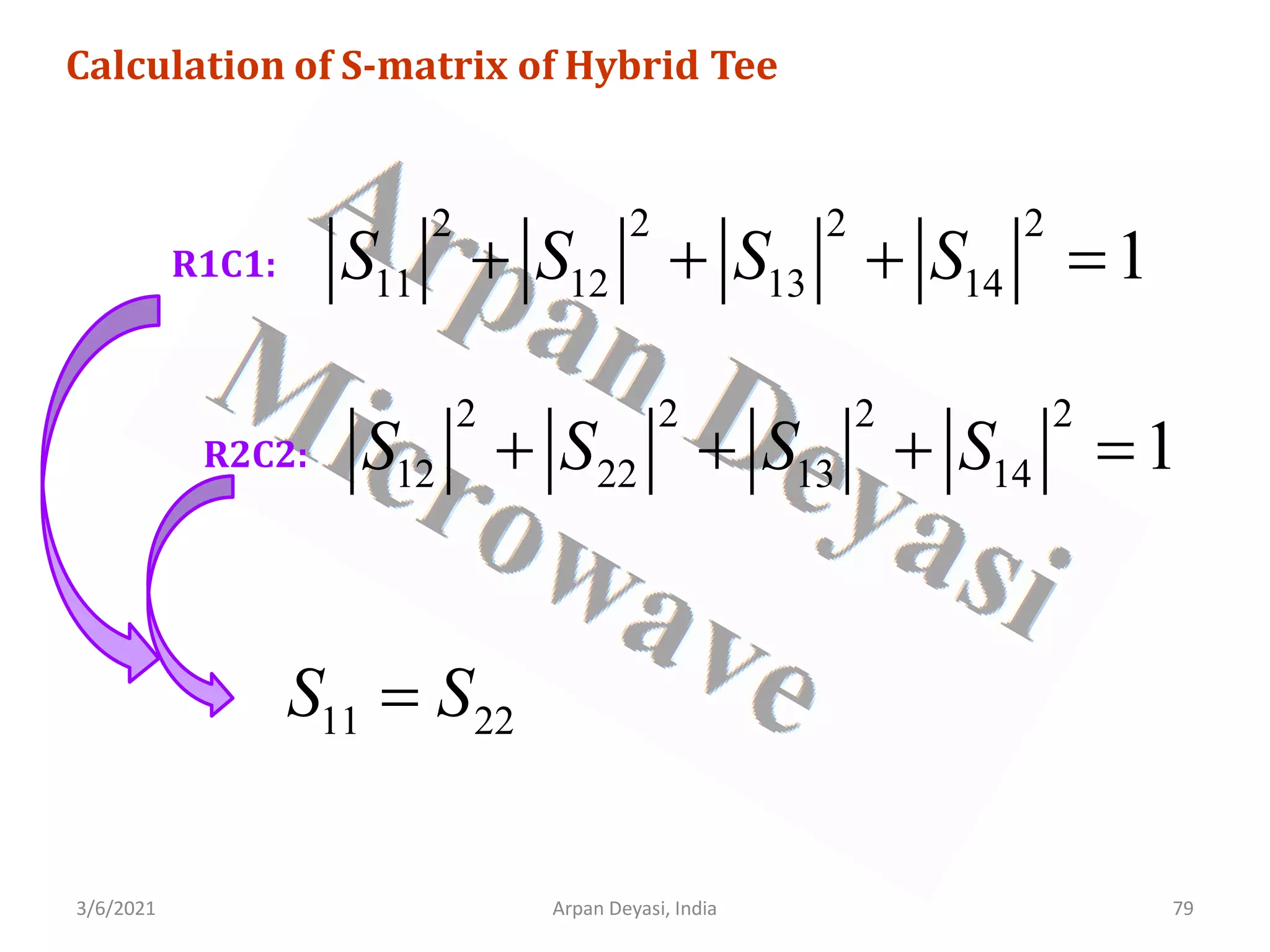
![3/6/2021 Arpan Deyasi, India 76
Calculation of S-matrix of Hybrid Tee
[ ]
11 12 13 14
12 22 13 14
13 13
14 14
0 0
0 0
S S S S
S S S S
S
S S
S S
−
=
−
](https://image.slidesharecdn.com/waveguidecomponents-210306082708/75/S-matrix-analysis-of-waveguide-components-76-2048.jpg)
![3/6/2021 Arpan Deyasi, India 77
Calculation of S-matrix of Hybrid Tee
using Unitary property
[ ][ ]
*
S S I
=
* * * *
11 12 13 14 11 12 13 14
* * * *
12 22 13 14 12 22 13 14
* *
13 13 13 13
* *
14 14 14 14
1 0 0 0
0 1 0 0
0 0 0 0 1 0
0 0
0 0 0 0 0 1
0 0
S S S S S S S S
S S S S S S S S
S S S S
S S S S
− −
=
− −
](https://image.slidesharecdn.com/waveguidecomponents-210306082708/75/S-matrix-analysis-of-waveguide-components-77-2048.jpg)
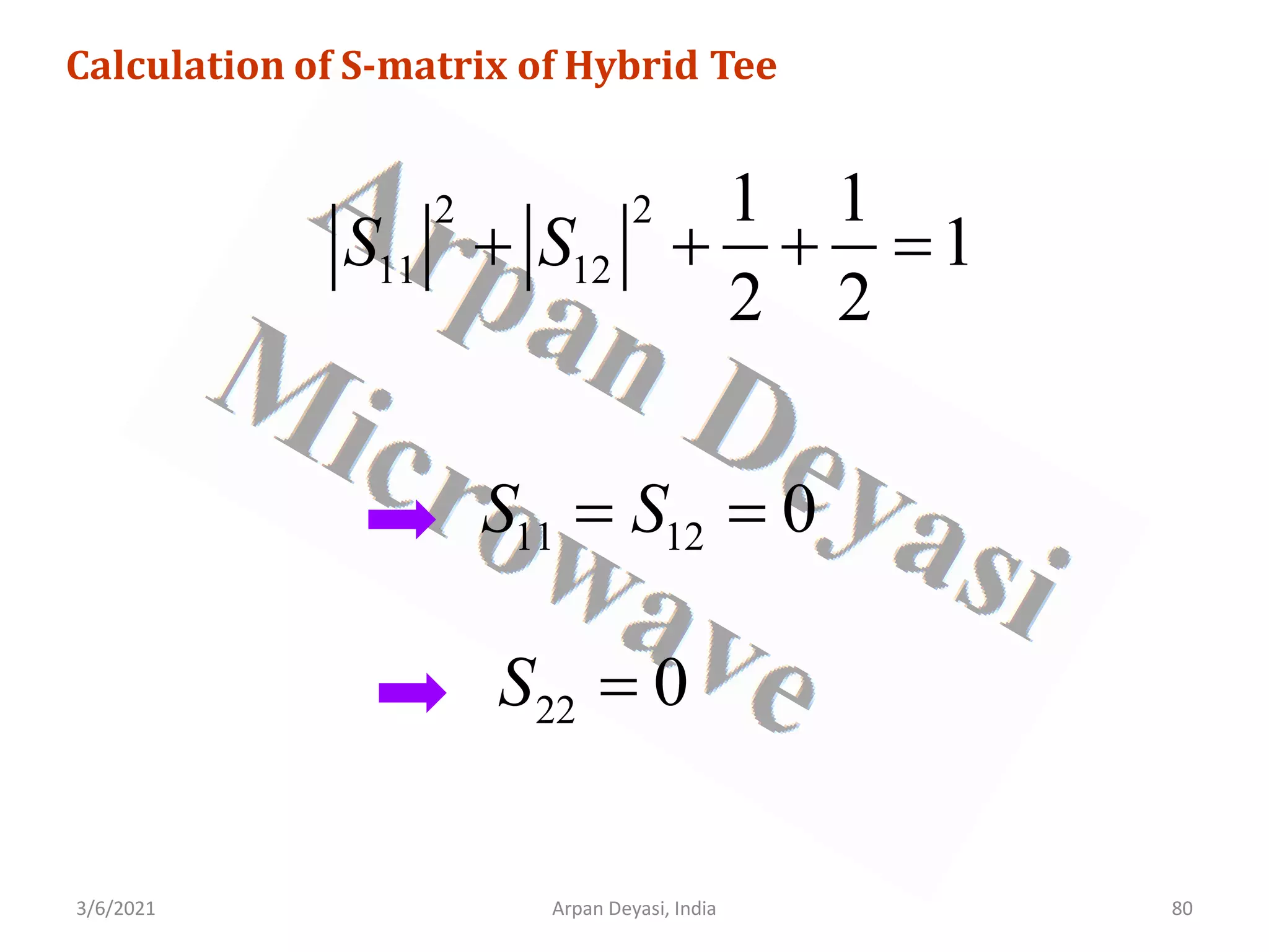
![3/6/2021 Arpan Deyasi, India 81
Calculation of S-matrix of Hybrid Tee
[ ]
1 1
0 0
2 2
1 1
0 0
2 2
1 1
0 0
2 2
1 1
0 0
2 2
S
−
=
−
](https://image.slidesharecdn.com/waveguidecomponents-210306082708/75/S-matrix-analysis-of-waveguide-components-81-2048.jpg)

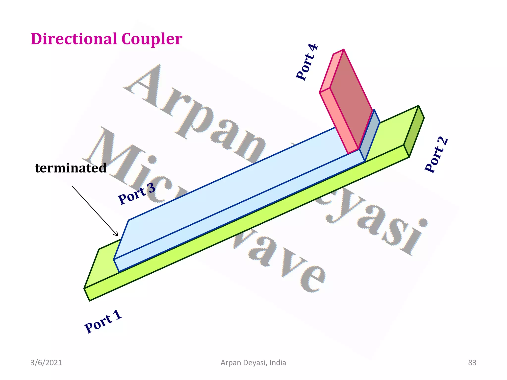
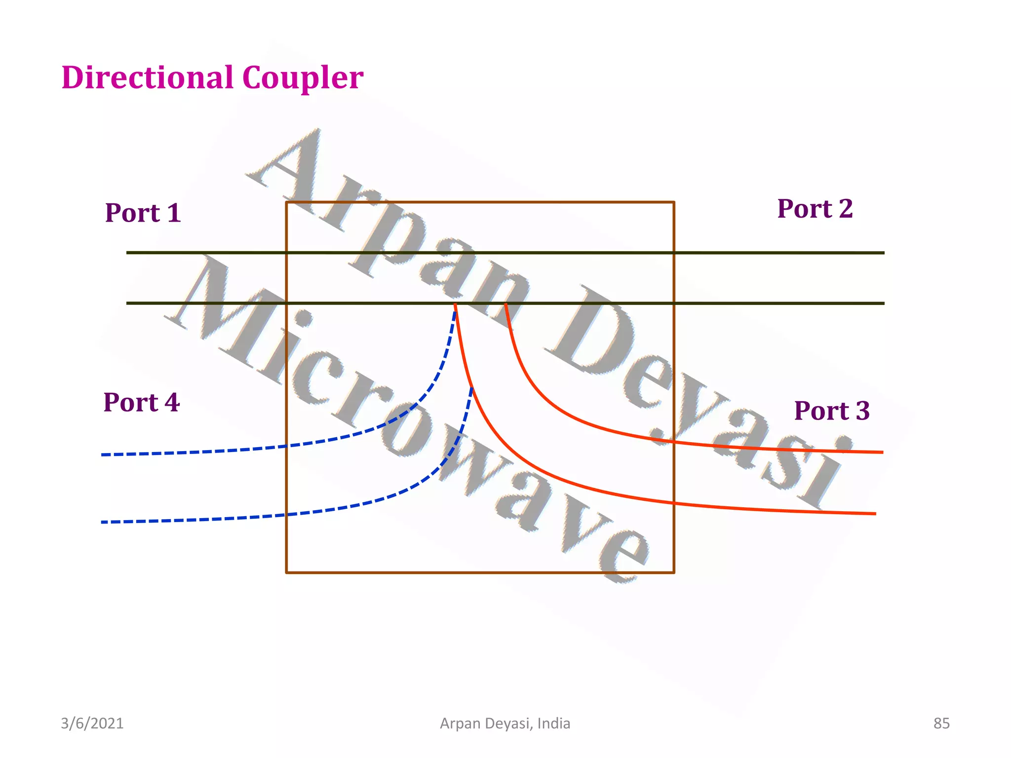
![3/6/2021 Arpan Deyasi, India 90
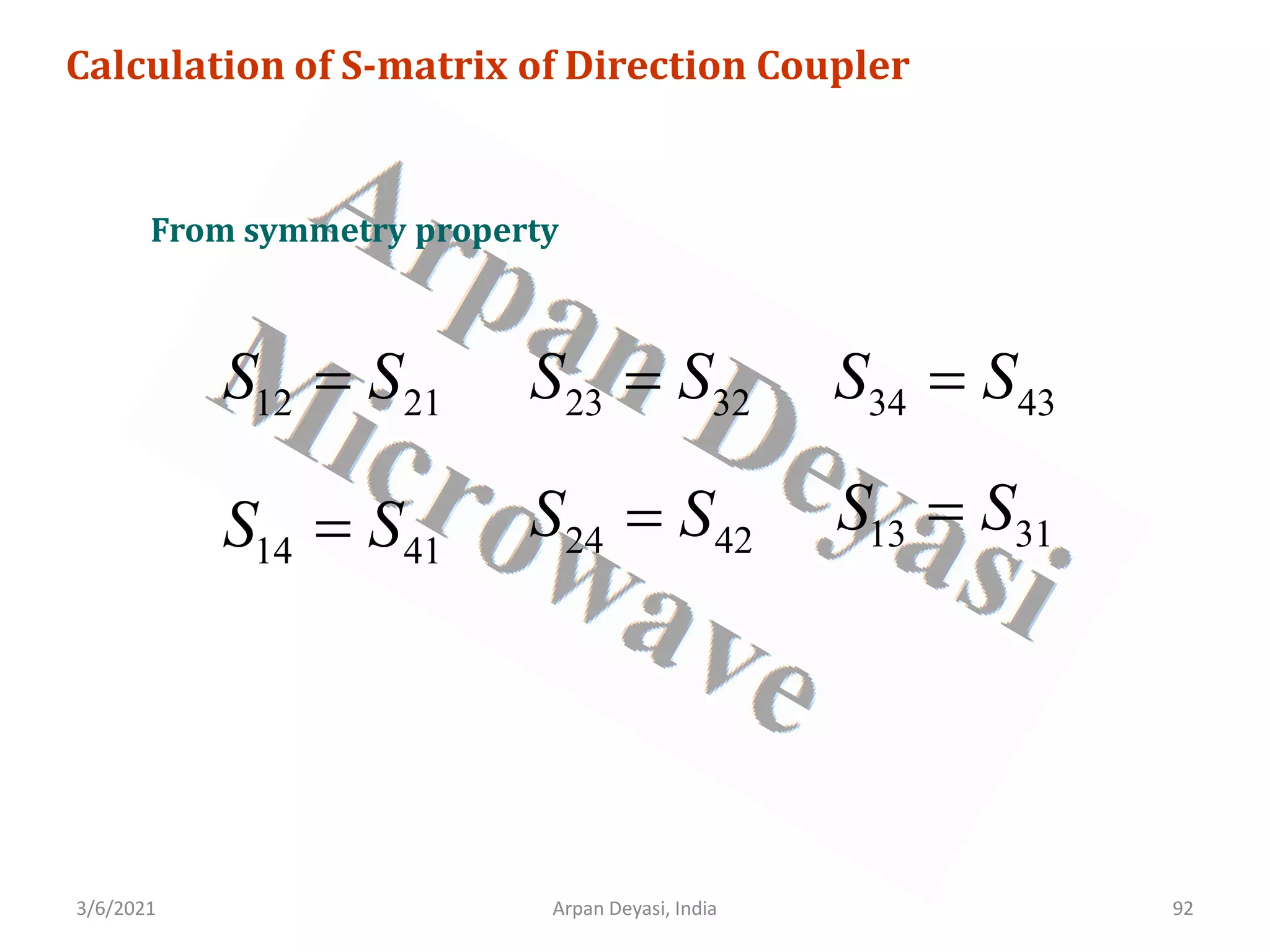
Calculation of S-matrix of Direction Coupler
General S-matrix of a Directional Coupler is
[ ]
11 12 13 14
21 22 23 24
31 32 33 34
41 42 43 44
S S S S
S S S S
S
S S S S
S S S S
=
](https://image.slidesharecdn.com/waveguidecomponents-210306082708/75/S-matrix-analysis-of-waveguide-components-90-2048.jpg)
![3/6/2021 Arpan Deyasi, India 91
Calculation of S-matrix of Direction Coupler
All four ports are perfectly matched
11 22 33 44 0
S S S S
= = = =
[ ]
12 13 14
21 23 24
31 32 34
41 42 43
0
0
0
0
S S S
S S S
S
S S S
S S S
=
](https://image.slidesharecdn.com/waveguidecomponents-210306082708/75/S-matrix-analysis-of-waveguide-components-91-2048.jpg)
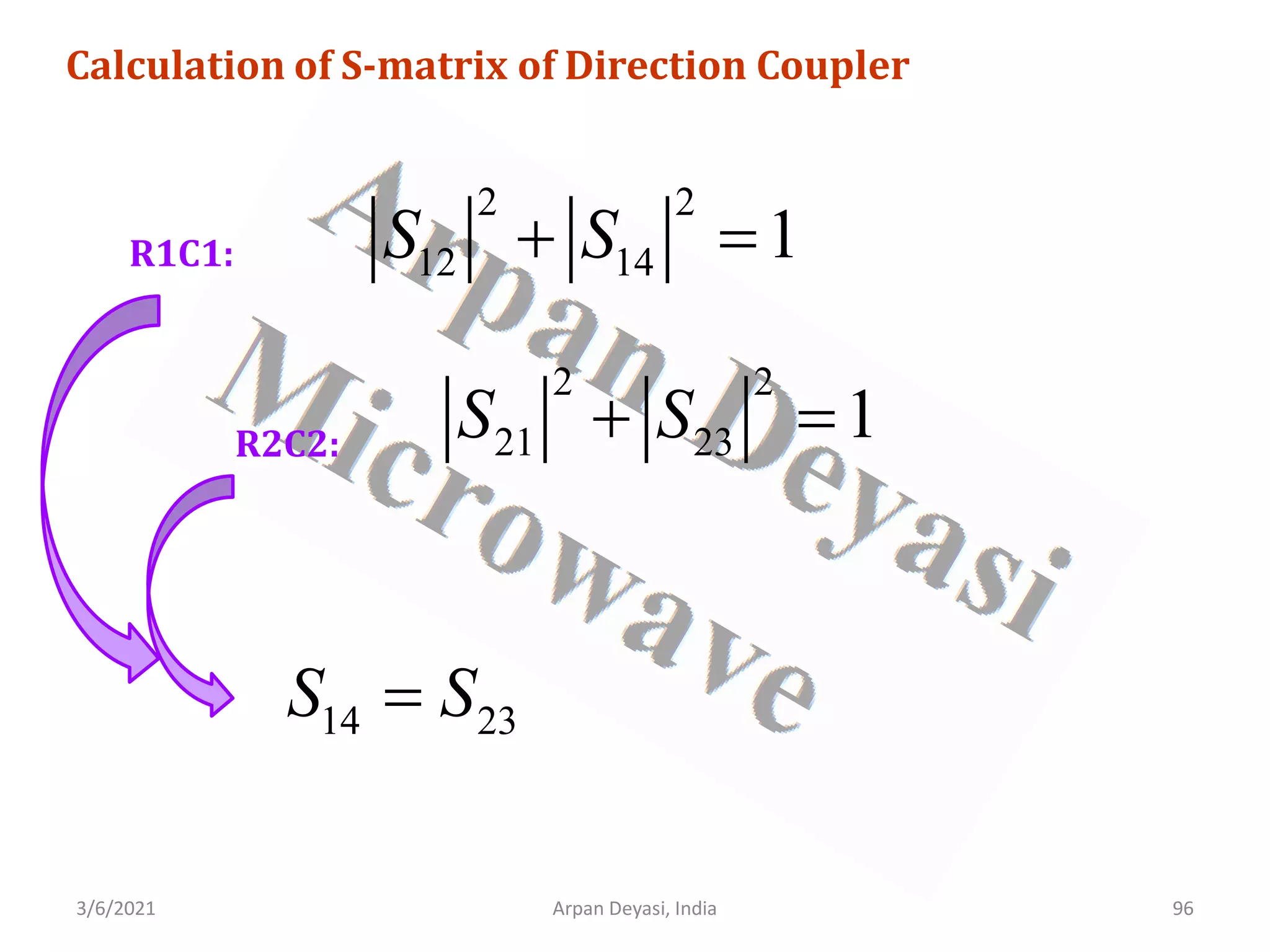
![3/6/2021 Arpan Deyasi, India 93
Calculation of S-matrix of Direction Coupler
No coupling between port 1 and port 3
13 31 0
S S
= =
[ ]
12 14
21 23 24
32 34
41 42 43
0 0
0
0 0
0
S S
S S S
S
S S
S S S
=
](https://image.slidesharecdn.com/waveguidecomponents-210306082708/75/S-matrix-analysis-of-waveguide-components-93-2048.jpg)
![3/6/2021 Arpan Deyasi, India 94
Calculation of S-matrix of Direction Coupler
No coupling between port 2 and port 4
24 42 0
S S
= =
[ ]
12 14
21 23
32 34
41 43
0 0
0 0
0 0
0 0
S S
S S
S
S S
S S
=
](https://image.slidesharecdn.com/waveguidecomponents-210306082708/75/S-matrix-analysis-of-waveguide-components-94-2048.jpg)
![3/6/2021 Arpan Deyasi, India 95
Calculation of S-matrix of Direction Coupler
using Unitary property
[ ][ ]
*
S S I
=
* *
12 14 12 14
* *
21 23 21 23
* *
32 34 32 34
* *
41 43 41 43
0 0 1 0 0 0
0 0
0 0 0 1 0 0
0 0
0 0 0 0 1 0
0 0
0 0 0 0 0 1
0 0
S S S S
S S S S
S S S S
S S S S
=
](https://image.slidesharecdn.com/waveguidecomponents-210306082708/75/S-matrix-analysis-of-waveguide-components-95-2048.jpg)

![3/6/2021 Arpan Deyasi, India 98
Calculation of S-matrix of Direction Coupler
[ ]
12 14
12 14
14 12
14 12
0 0
0 0
0 0
0 0
S S
S S
S
S S
S S
=
](https://image.slidesharecdn.com/waveguidecomponents-210306082708/75/S-matrix-analysis-of-waveguide-components-98-2048.jpg)
![3/6/2021 Arpan Deyasi, India 99
Calculation of S-matrix of Direction Coupler
Let S12 is real and positive
R1C3:
12
S p
=
* *
12 23 14 43 0
S S S S
+ =
*
23 14
. . 0
p S S p
+ =
*
23 23
[ ] 0
p S S
+ =](https://image.slidesharecdn.com/waveguidecomponents-210306082708/75/S-matrix-analysis-of-waveguide-components-99-2048.jpg)
![3/6/2021 Arpan Deyasi, India 100
Calculation of S-matrix of Direction Coupler
To satisfy the condition, S23 should be complex quantity
23 14
S S jq
= =
[ ]
0 0
0 0
0 0
0 0
p jq
p jq
S
jq p
jq p
=
](https://image.slidesharecdn.com/waveguidecomponents-210306082708/75/S-matrix-analysis-of-waveguide-components-100-2048.jpg)

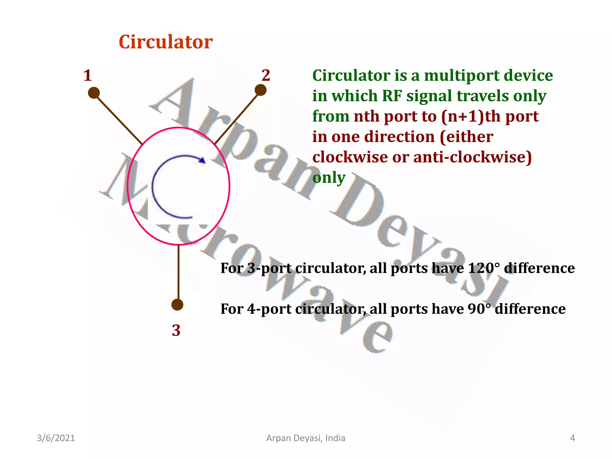
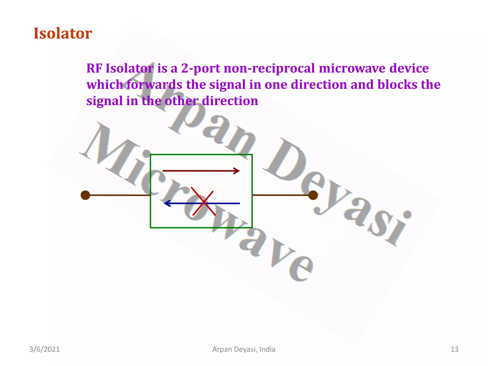
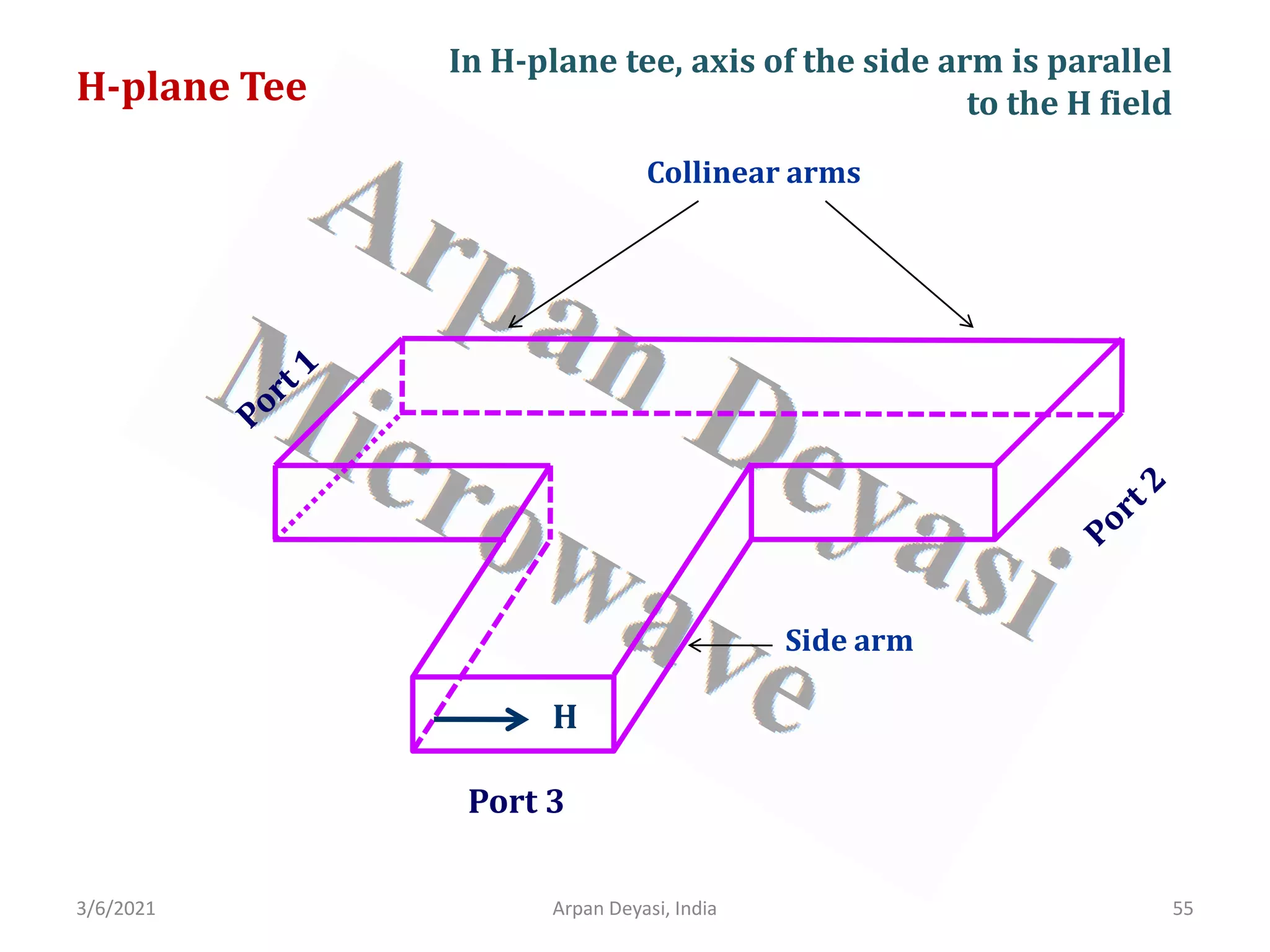
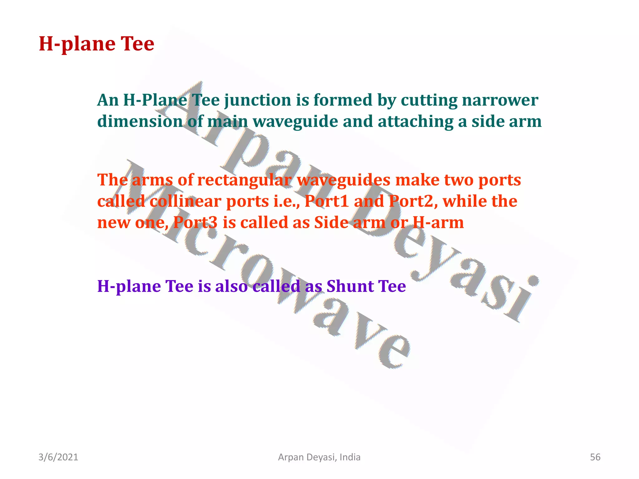
This document discusses waveguide components and their S-matrix analysis. It begins with an introduction and overview of isolators, attenuators, circulators and gyrators. It then provides detailed calculations of the S-matrix for a 3-port circulator, 2-port isolator, 2-port gyrator and 2-port attenuator. The document also discusses Faraday rotation isolators, E-plane and H-plane waveguide tees, and includes the calculation of the S-matrix for an E-plane tee.


![RF Circuit Design - [Ch3-1] Microwave Network](https://cdn.slidesharecdn.com/ss_thumbnails/ch3-1-150613064402-lva1-app6892-thumbnail.jpg?width=640&height=640&fit=bounds)


