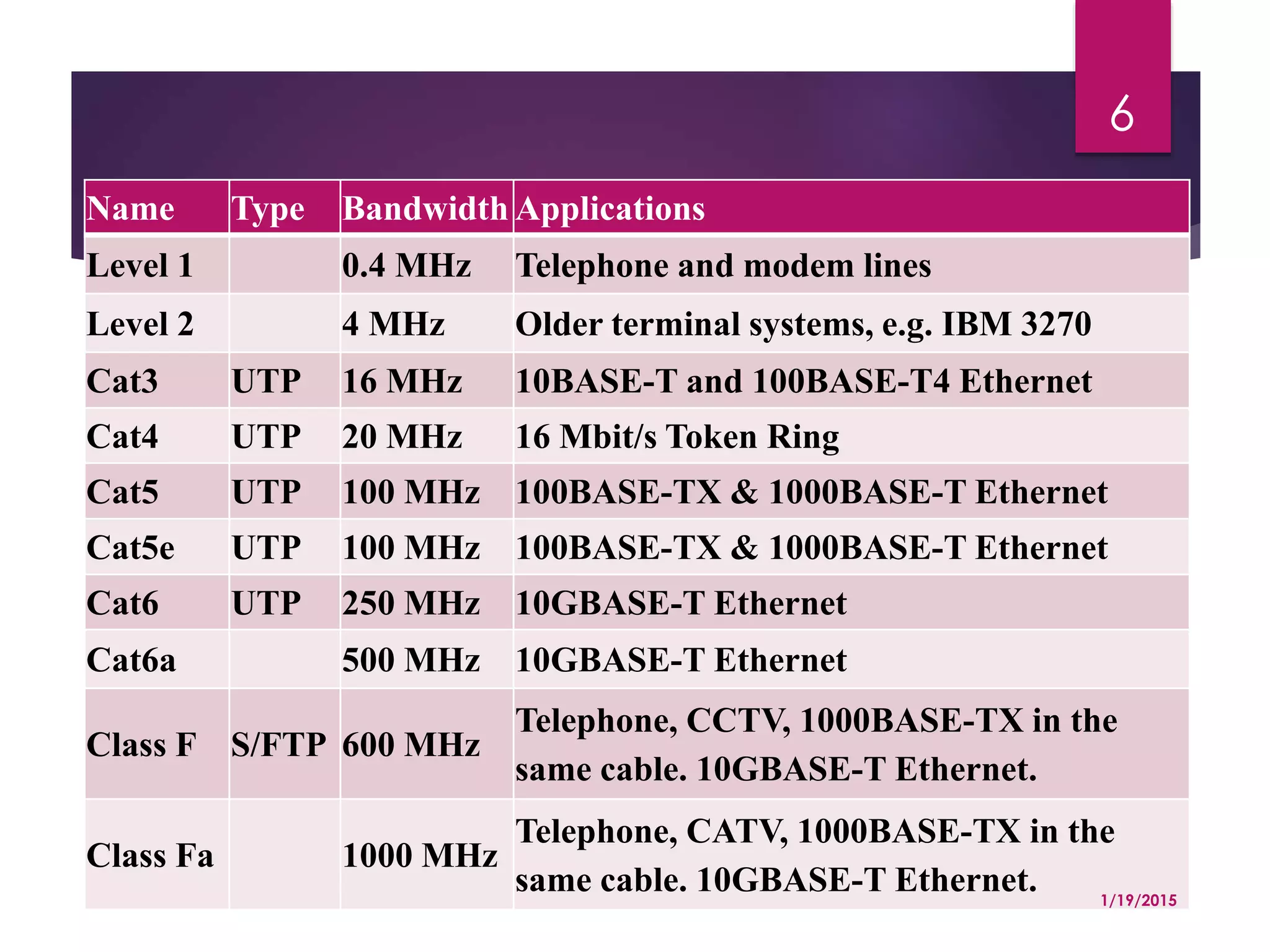
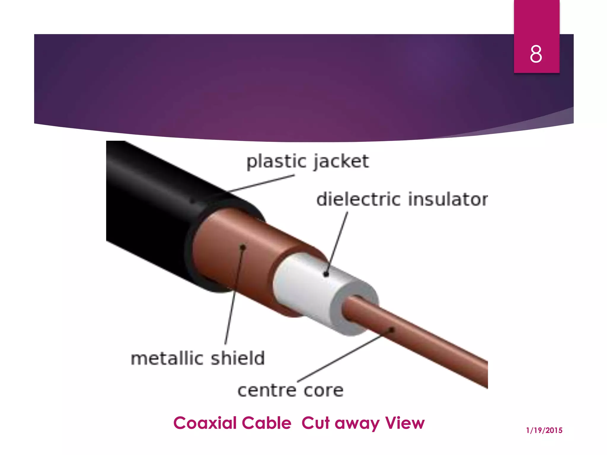
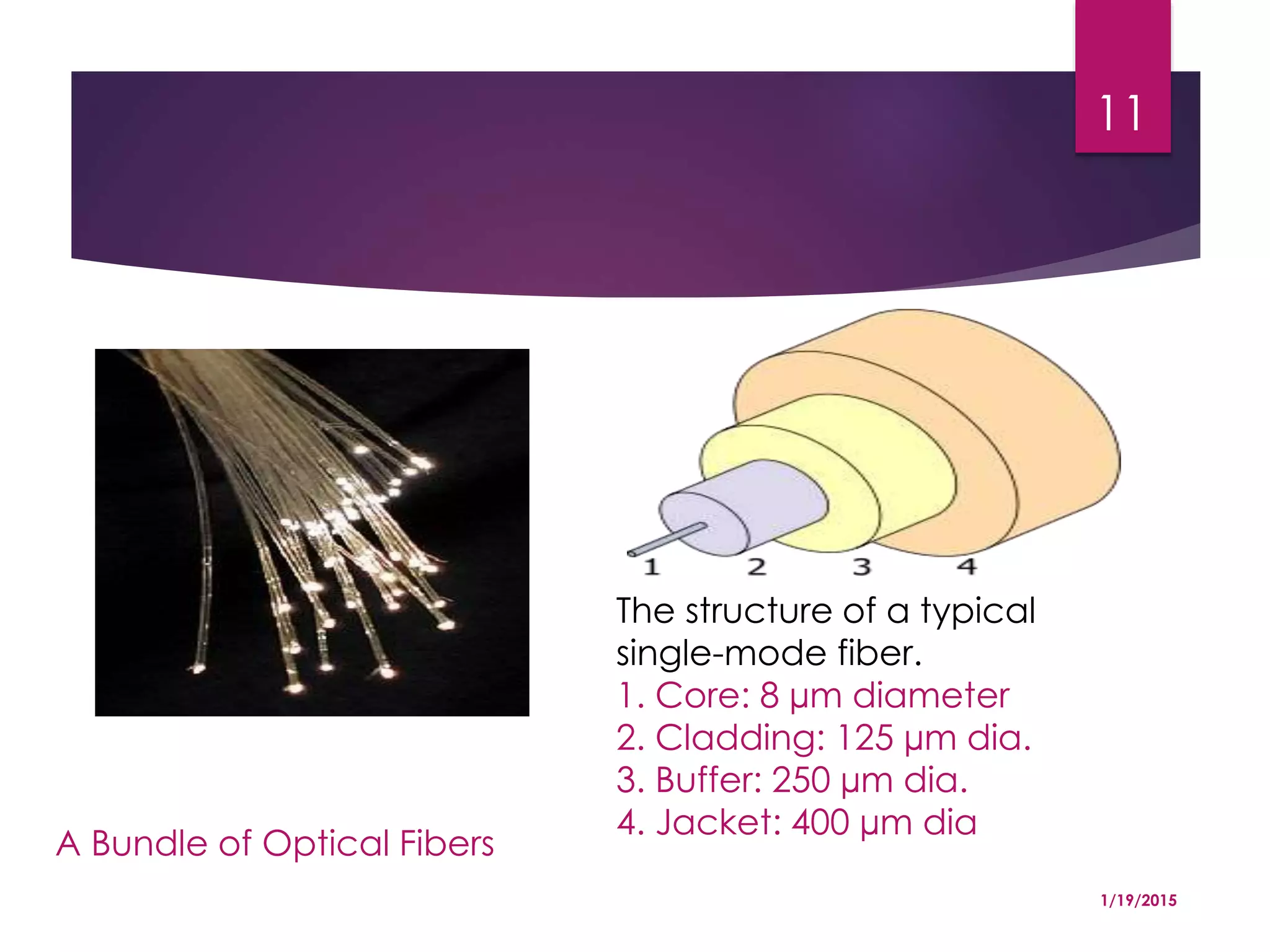
Media Concept and
classification of Media
1
Presenter:
Purushottam Dahal
https://www.facebook.com/puru.BIM
Contents
 Guided Media
 Twisted pair overview
 Coaxial cable overview
 Fiber optics overview
 Unguided Media
 VSAT
 Satellite
 Transmission Characteristics
 Attenuation
 Noise
 Signal to Noise Ratio
 Propagation Delay 1/19/2015
2
Guided Transmission Media
 Purpose is to transfer raw bit stream
 Related with physical layer
 Various physical medias can be used
 Magnetic media, removable medias
 Transfer rate, depends upon distance and media
used. Same media may contain various transfer
rates with high degree of variation.
1/19/2015
3
Twisted Pair
 Bandwidth characteristics of Magnetic tape and other removable
media is excellent, the delay characteristics is very poor.
 Transmission time is measured in minutes or hours, not milliseconds.
 One of the oldest and still most common transmission media is twisted
pair
 A cable made by intertwining two separate insulated wires together
1/19/2015
4
Types of Twisted Pair
UTP STP
1/19/2015
5
Name Type Bandwidth Applications
Level 1 0.4 MHz Telephone and modem lines
Level 2 4 MHz Older terminal systems, e.g. IBM 3270
Cat3 UTP 16 MHz 10BASE-T and 100BASE-T4 Ethernet
Cat4 UTP 20 MHz 16 Mbit/s Token Ring
Cat5 UTP 100 MHz 100BASE-TX & 1000BASE-T Ethernet
Cat5e UTP 100 MHz 100BASE-TX & 1000BASE-T Ethernet
Cat6 UTP 250 MHz 10GBASE-T Ethernet
Cat6a 500 MHz 10GBASE-T Ethernet
Class F S/FTP 600 MHz
Telephone, CCTV, 1000BASE-TX in the
same cable. 10GBASE-T Ethernet.
Class Fa 1000 MHz
Telephone, CATV, 1000BASE-TX in the
same cable. 10GBASE-T Ethernet. 1/19/2015
6
Co-axial Cable
 It has better shielding than twisted pairs, so it can span longer
distances at higher speeds.
 Two kinds of coaxial cable are widely used.
 One kind, 50-ohm cable, is commonly used when it is intended for
digital transmission from the start. The other kind, 75-ohm cable, is
commonly used for analog transmission and CATV, but is becoming
more important with the advent of Internet over cable.
 The construction and shielding of the coaxial cable give it a good
combination of high bandwidth and excellent noise immunity.
 The bandwidth possible depends on the cable quality, length, and
signal-to-noise ratio of the data signal.
 Modern cables have a bandwidth of close to 1 GHz.
1/19/2015
7
Coaxial Cable Cut away View 1/19/2015
8
Fiber Optics
 A technology that uses glass (or plastic) threads (fibers) to transmit data. A
fiber optic cable consists of a bundle of glass threads, each of which is
capable of transmitting messages modulated onto light waves.
 An optical transmission system has three key components: the light source,
the transmission medium, and the detector.
 Conventionally, a pulse of light indicates a 1 bit and the absence of light
indicates a 0 bit.
 The transmission medium is an ultra-thin fiber of glass. The detector
generates an electrical pulse when light falls on it.
 By attaching a light source to one end of an optical fiber and a detector
to the other, we have a unidirectional data transmission system that
accepts an electrical signal, converts and transmits it by light pulses, and
then reconverts the output to an electrical signal at the receiving end.
1/19/2015
9
CONT……..
 Fiber optics has several advantages over traditional metal
communications lines:
 Fiber optic cables have a much greater bandwidth than metal
cables. This means that they can carry more data.
 Fiber optic cables are less susceptible than metal cables to
interference.
 Fiber optic cables are much thinner and lighter than metal wires.
 Data can be transmitted digitally (the natural form for computer
data) rather than analogically.
1/19/2015
10
A Bundle of Optical Fibers
The structure of a typical
single-mode fiber.
1. Core: 8 µm diameter
2. Cladding: 125 µm dia.
3. Buffer: 250 µm dia.
4. Jacket: 400 µm dia
1/19/2015
11
VSAT
 A very small aperture terminal (VSAT), is a two-way satellite ground
station or a stabilized maritime VSAT antenna with a dish antenna that
is smaller than 3 meters.
 The majority of VSAT antennas range from 75 cm to 1.2 m.
 Data rates range from 4 Kbit/s up to 4 Mbit/s; some upgraded
modules can even reach a max downlink of up to 16 Mbit/s.
 VSATs access satellites in geosynchronous orbit to relay data from
small remote earth stations (terminals) to other terminals (in mesh
topology) or master earth station "hubs" (in star topology).
1/19/2015
12
Satellite
 A satellite is an artificial object which has been intentionally placed
into orbit.
 Such objects are sometimes called artificial satellites to distinguish
them from natural satellites such as the Moon.
 Satellite is a specialized wireless receiver/transmitter that is launched
by a rocket and placed in orbit around the earth.
 There are hundreds of satellites currently in operation. They are used
for such diverse purposes as weather forecasting, television broadcast,
amateur radio communications, Internet communications, and the
Global Positioning System(GPS).
1/19/2015
13
Attenuation
 Attenuation is a general term that refers to any reduction in the
strength of a signal.
 Attenuation is a general term that refers to any reduction in the
strength of a signal.
 Attenuation occurs with any type of signal, whether digital or
analog.
 Sometimes called loss, attenuation is a natural consequence of
signal transmission over long distances.
 The extent of attenuation is usually expressed in units called
decibels (dBs).
1/19/2015
14
Noise
 Noise is unwanted electrical or electromagnetic energy that degrades
the quality of signals and data.
 Noise occurs in digital and analog systems, and can affect files and
communications of all types, including text, programs, images, audio,
and telemetry.
 In a hard-wired circuit such as a telephone-line-based Internet hookup,
external noise is picked up from appliances in the vicinity, from electrical
transformers, from the atmosphere, and even from outer space.
 Normally this noise is of little or no consequence. However, during severe
thunderstorms, or in locations were many electrical appliances are in
use, external noise can affect communications.
 In an Internet hookup it slows down the data transfer rate, because the
system must adjust its speed to match conditions on the line. In a voice
telephone conversation, noise rarely sounds like anything other than a
faint hissing or rushing.
1/19/2015
15
Signal-to-Noise Ratio
 In analog and digital communications, signal-to-
noise ratio, often written S/N or SNR, is a measure of
signal strength relative to background noise.
 The ratio is usually measured in decibels (dB).
 Communications engineers always strive to
maximize the S/N ratio.
1/19/2015
16
Propagation Delay
 Propagation delay is the amount of time it takes for the head of the
signal to travel from the sender to the receiver.
 Propagation delay refers to the time lag between the departure of
a signal from the source and the arrival of the signal at the
destination.
 It can be computed as the ratio between the link length and the
propagation speed over the specific medium.
1/19/2015
17
“
”
THANK YOU
1/19/2015
18

Media Concept and classification of Media

  • 1.
    Media Concept and classificationof Media 1 Presenter: Purushottam Dahal https://www.facebook.com/puru.BIM
  • 2.
    Contents  Guided Media Twisted pair overview  Coaxial cable overview  Fiber optics overview  Unguided Media  VSAT  Satellite  Transmission Characteristics  Attenuation  Noise  Signal to Noise Ratio  Propagation Delay 1/19/2015 2
  • 3.
    Guided Transmission Media Purpose is to transfer raw bit stream  Related with physical layer  Various physical medias can be used  Magnetic media, removable medias  Transfer rate, depends upon distance and media used. Same media may contain various transfer rates with high degree of variation. 1/19/2015 3
  • 4.
    Twisted Pair  Bandwidthcharacteristics of Magnetic tape and other removable media is excellent, the delay characteristics is very poor.  Transmission time is measured in minutes or hours, not milliseconds.  One of the oldest and still most common transmission media is twisted pair  A cable made by intertwining two separate insulated wires together 1/19/2015 4
  • 5.
    Types of TwistedPair UTP STP 1/19/2015 5
  • 6.
    Name Type BandwidthApplications Level 1 0.4 MHz Telephone and modem lines Level 2 4 MHz Older terminal systems, e.g. IBM 3270 Cat3 UTP 16 MHz 10BASE-T and 100BASE-T4 Ethernet Cat4 UTP 20 MHz 16 Mbit/s Token Ring Cat5 UTP 100 MHz 100BASE-TX & 1000BASE-T Ethernet Cat5e UTP 100 MHz 100BASE-TX & 1000BASE-T Ethernet Cat6 UTP 250 MHz 10GBASE-T Ethernet Cat6a 500 MHz 10GBASE-T Ethernet Class F S/FTP 600 MHz Telephone, CCTV, 1000BASE-TX in the same cable. 10GBASE-T Ethernet. Class Fa 1000 MHz Telephone, CATV, 1000BASE-TX in the same cable. 10GBASE-T Ethernet. 1/19/2015 6
  • 7.
    Co-axial Cable  Ithas better shielding than twisted pairs, so it can span longer distances at higher speeds.  Two kinds of coaxial cable are widely used.  One kind, 50-ohm cable, is commonly used when it is intended for digital transmission from the start. The other kind, 75-ohm cable, is commonly used for analog transmission and CATV, but is becoming more important with the advent of Internet over cable.  The construction and shielding of the coaxial cable give it a good combination of high bandwidth and excellent noise immunity.  The bandwidth possible depends on the cable quality, length, and signal-to-noise ratio of the data signal.  Modern cables have a bandwidth of close to 1 GHz. 1/19/2015 7
  • 8.
    Coaxial Cable Cutaway View 1/19/2015 8
  • 9.
    Fiber Optics  Atechnology that uses glass (or plastic) threads (fibers) to transmit data. A fiber optic cable consists of a bundle of glass threads, each of which is capable of transmitting messages modulated onto light waves.  An optical transmission system has three key components: the light source, the transmission medium, and the detector.  Conventionally, a pulse of light indicates a 1 bit and the absence of light indicates a 0 bit.  The transmission medium is an ultra-thin fiber of glass. The detector generates an electrical pulse when light falls on it.  By attaching a light source to one end of an optical fiber and a detector to the other, we have a unidirectional data transmission system that accepts an electrical signal, converts and transmits it by light pulses, and then reconverts the output to an electrical signal at the receiving end. 1/19/2015 9
  • 10.
    CONT……..  Fiber opticshas several advantages over traditional metal communications lines:  Fiber optic cables have a much greater bandwidth than metal cables. This means that they can carry more data.  Fiber optic cables are less susceptible than metal cables to interference.  Fiber optic cables are much thinner and lighter than metal wires.  Data can be transmitted digitally (the natural form for computer data) rather than analogically. 1/19/2015 10
  • 11.
    A Bundle ofOptical Fibers The structure of a typical single-mode fiber. 1. Core: 8 µm diameter 2. Cladding: 125 µm dia. 3. Buffer: 250 µm dia. 4. Jacket: 400 µm dia 1/19/2015 11
  • 12.
    VSAT  A verysmall aperture terminal (VSAT), is a two-way satellite ground station or a stabilized maritime VSAT antenna with a dish antenna that is smaller than 3 meters.  The majority of VSAT antennas range from 75 cm to 1.2 m.  Data rates range from 4 Kbit/s up to 4 Mbit/s; some upgraded modules can even reach a max downlink of up to 16 Mbit/s.  VSATs access satellites in geosynchronous orbit to relay data from small remote earth stations (terminals) to other terminals (in mesh topology) or master earth station "hubs" (in star topology). 1/19/2015 12
  • 13.
    Satellite  A satelliteis an artificial object which has been intentionally placed into orbit.  Such objects are sometimes called artificial satellites to distinguish them from natural satellites such as the Moon.  Satellite is a specialized wireless receiver/transmitter that is launched by a rocket and placed in orbit around the earth.  There are hundreds of satellites currently in operation. They are used for such diverse purposes as weather forecasting, television broadcast, amateur radio communications, Internet communications, and the Global Positioning System(GPS). 1/19/2015 13
  • 14.
    Attenuation  Attenuation isa general term that refers to any reduction in the strength of a signal.  Attenuation is a general term that refers to any reduction in the strength of a signal.  Attenuation occurs with any type of signal, whether digital or analog.  Sometimes called loss, attenuation is a natural consequence of signal transmission over long distances.  The extent of attenuation is usually expressed in units called decibels (dBs). 1/19/2015 14
  • 15.
    Noise  Noise isunwanted electrical or electromagnetic energy that degrades the quality of signals and data.  Noise occurs in digital and analog systems, and can affect files and communications of all types, including text, programs, images, audio, and telemetry.  In a hard-wired circuit such as a telephone-line-based Internet hookup, external noise is picked up from appliances in the vicinity, from electrical transformers, from the atmosphere, and even from outer space.  Normally this noise is of little or no consequence. However, during severe thunderstorms, or in locations were many electrical appliances are in use, external noise can affect communications.  In an Internet hookup it slows down the data transfer rate, because the system must adjust its speed to match conditions on the line. In a voice telephone conversation, noise rarely sounds like anything other than a faint hissing or rushing. 1/19/2015 15
  • 16.
    Signal-to-Noise Ratio  Inanalog and digital communications, signal-to- noise ratio, often written S/N or SNR, is a measure of signal strength relative to background noise.  The ratio is usually measured in decibels (dB).  Communications engineers always strive to maximize the S/N ratio. 1/19/2015 16
  • 17.
    Propagation Delay  Propagationdelay is the amount of time it takes for the head of the signal to travel from the sender to the receiver.  Propagation delay refers to the time lag between the departure of a signal from the source and the arrival of the signal at the destination.  It can be computed as the ratio between the link length and the propagation speed over the specific medium. 1/19/2015 17
  • 18.