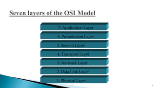
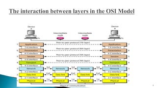
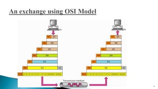
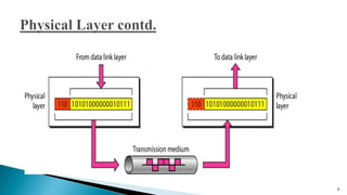
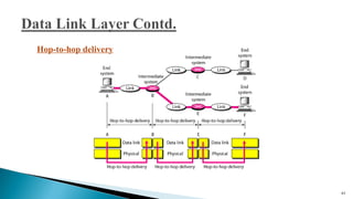
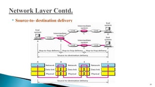
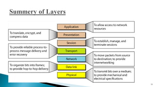
The document discusses the seven layers of the Open Systems Interconnection (OSI) model, with a focus on the physical and data link layers. It describes the key responsibilities of the physical layer, including representing bits, synchronizing data transmission, defining transmission media and topology. It also outlines the major duties of the data link layer, such as framing data, implementing addressing, and handling errors.
OSI layers describes how the data can be send from one parties to another during data communication. it also gives the detailed information of how the data functionally divided into small pieces and reaches the destination.
ISO is an organization which is established in 1947.
AN ISO standard that covers all aspects of network communication.
Network communication model is defined in OSI.
It was first introduced in the late 1970s, 1983
The Open Systems Interconnection model (OSI model) is a conceptual model that characterizes and standardizes the communication functions of a telecommunication or computing system without regard to its underlying internal structure and technology.
7 Layers OSI model description with 3 unofficial Layers.Kanishk Raj
OSI reference model all seven layers description with 8,9,&10 not official layers that is also important in an organization ,when design the effective Network output.
BGP (Border Gateway Routing Protocol) is a standardized exterior gateway protocol designed to
exchange routing and reachability information between autonomous systems (AS) on the Internet. The
Border Gateway Protocol makes routing decisions based on paths, network policies or rule-sets
configured by a network administrator, and are involved in making core routing decisions.
BGP is a very robust and scalable routing protocol, as evidenced by the fact that BGP is the routing
protocol employed on the Internet.
Here I describe all of OSI MODEL layer and their purposes.
And also discuss about their protocol.which protocol are using in OSI MODEL. By reading this slide your basic concept in OSI MODEL will be clear and easy.
Final project report on grocery store management system..pdfKamal Acharya
In today’s fast-changing business environment, it’s extremely important to be able to respond to client needs in the most effective and timely manner. If your customers wish to see your business online and have instant access to your products or services.
Online Grocery Store is an e-commerce website, which retails various grocery products. This project allows viewing various products available enables registered users to purchase desired products instantly using Paytm, UPI payment processor (Instant Pay) and also can place order by using Cash on Delivery (Pay Later) option. This project provides an easy access to Administrators and Managers to view orders placed using Pay Later and Instant Pay options.
In order to develop an e-commerce website, a number of Technologies must be studied and understood. These include multi-tiered architecture, server and client-side scripting techniques, implementation technologies, programming language (such as PHP, HTML, CSS, JavaScript) and MySQL relational databases. This is a project with the objective to develop a basic website where a consumer is provided with a shopping cart website and also to know about the technologies used to develop such a website.
This document will discuss each of the underlying technologies to create and implement an e- commerce website.
Automobile Management System Project Report.pdfKamal Acharya
The proposed project is developed to manage the automobile in the automobile dealer company. The main module in this project is login, automobile management, customer management, sales, complaints and reports. The first module is the login. The automobile showroom owner should login to the project for usage. The username and password are verified and if it is correct, next form opens. If the username and password are not correct, it shows the error message.
When a customer search for a automobile, if the automobile is available, they will be taken to a page that shows the details of the automobile including automobile name, automobile ID, quantity, price etc. “Automobile Management System” is useful for maintaining automobiles, customers effectively and hence helps for establishing good relation between customer and automobile organization. It contains various customized modules for effectively maintaining automobiles and stock information accurately and safely.
When the automobile is sold to the customer, stock will be reduced automatically. When a new purchase is made, stock will be increased automatically. While selecting automobiles for sale, the proposed software will automatically check for total number of available stock of that particular item, if the total stock of that particular item is less than 5, software will notify the user to purchase the particular item.
Also when the user tries to sale items which are not in stock, the system will prompt the user that the stock is not enough. Customers of this system can search for a automobile; can purchase a automobile easily by selecting fast. On the other hand the stock of automobiles can be maintained perfectly by the automobile shop manager overcoming the drawbacks of existing system.
Immunizing Image Classifiers Against Localized Adversary Attacksgerogepatton
This paper addresses the vulnerability of deep learning models, particularly convolutional neural networks
(CNN)s, to adversarial attacks and presents a proactive training technique designed to counter them. We
introduce a novel volumization algorithm, which transforms 2D images into 3D volumetric representations.
When combined with 3D convolution and deep curriculum learning optimization (CLO), itsignificantly improves
the immunity of models against localized universal attacks by up to 40%. We evaluate our proposed approach
using contemporary CNN architectures and the modified Canadian Institute for Advanced Research (CIFAR-10
and CIFAR-100) and ImageNet Large Scale Visual Recognition Challenge (ILSVRC12) datasets, showcasing
accuracy improvements over previous techniques. The results indicate that the combination of the volumetric
input and curriculum learning holds significant promise for mitigating adversarial attacks without necessitating
adversary training.
Industrial Training at Shahjalal Fertilizer Company Limited (SFCL)MdTanvirMahtab2
This presentation is about the working procedure of Shahjalal Fertilizer Company Limited (SFCL). A Govt. owned Company of Bangladesh Chemical Industries Corporation under Ministry of Industries.
Overview of the fundamental roles in Hydropower generation and the components involved in wider Electrical Engineering.
This paper presents the design and construction of hydroelectric dams from the hydrologist’s survey of the valley before construction, all aspects and involved disciplines, fluid dynamics, structural engineering, generation and mains frequency regulation to the very transmission of power through the network in the United Kingdom.
Author: Robbie Edward Sayers
Collaborators and co editors: Charlie Sims and Connor Healey.
(C) 2024 Robbie E. Sayers
Student information management system project report ii.pdfKamal Acharya
Our project explains about the student management. This project mainly explains the various actions related to student details. This project shows some ease in adding, editing and deleting the student details. It also provides a less time consuming process for viewing, adding, editing and deleting the marks of the students.
NO1 Uk best vashikaran specialist in delhi vashikaran baba near me online vas...Amil Baba Dawood bangali
Contact with Dawood Bhai Just call on +92322-6382012 and we'll help you. We'll solve all your problems within 12 to 24 hours and with 101% guarantee and with astrology systematic. If you want to take any personal or professional advice then also you can call us on +92322-6382012 , ONLINE LOVE PROBLEM & Other all types of Daily Life Problem's.Then CALL or WHATSAPP us on +92322-6382012 and Get all these problems solutions here by Amil Baba DAWOOD BANGALI
#vashikaranspecialist #astrologer #palmistry #amliyaat #taweez #manpasandshadi #horoscope #spiritual #lovelife #lovespell #marriagespell#aamilbabainpakistan #amilbabainkarachi #powerfullblackmagicspell #kalajadumantarspecialist #realamilbaba #AmilbabainPakistan #astrologerincanada #astrologerindubai #lovespellsmaster #kalajaduspecialist #lovespellsthatwork #aamilbabainlahore#blackmagicformarriage #aamilbaba #kalajadu #kalailam #taweez #wazifaexpert #jadumantar #vashikaranspecialist #astrologer #palmistry #amliyaat #taweez #manpasandshadi #horoscope #spiritual #lovelife #lovespell #marriagespell#aamilbabainpakistan #amilbabainkarachi #powerfullblackmagicspell #kalajadumantarspecialist #realamilbaba #AmilbabainPakistan #astrologerincanada #astrologerindubai #lovespellsmaster #kalajaduspecialist #lovespellsthatwork #aamilbabainlahore #blackmagicforlove #blackmagicformarriage #aamilbaba #kalajadu #kalailam #taweez #wazifaexpert #jadumantar #vashikaranspecialist #astrologer #palmistry #amliyaat #taweez #manpasandshadi #horoscope #spiritual #lovelife #lovespell #marriagespell#aamilbabainpakistan #amilbabainkarachi #powerfullblackmagicspell #kalajadumantarspecialist #realamilbaba #AmilbabainPakistan #astrologerincanada #astrologerindubai #lovespellsmaster #kalajaduspecialist #lovespellsthatwork #aamilbabainlahore #Amilbabainuk #amilbabainspain #amilbabaindubai #Amilbabainnorway #amilbabainkrachi #amilbabainlahore #amilbabaingujranwalan #amilbabainislamabad
Event Management System Vb Net Project Report.pdfKamal Acharya
In present era, the scopes of information technology growing with a very fast .We do not see any are untouched from this industry. The scope of information technology has become wider includes: Business and industry. Household Business, Communication, Education, Entertainment, Science, Medicine, Engineering, Distance Learning, Weather Forecasting. Carrier Searching and so on.
My project named “Event Management System” is software that store and maintained all events coordinated in college. It also helpful to print related reports. My project will help to record the events coordinated by faculties with their Name, Event subject, date & details in an efficient & effective ways.
In my system we have to make a system by which a user can record all events coordinated by a particular faculty. In our proposed system some more featured are added which differs it from the existing system such as security.
Forklift Classes Overview by Intella PartsIntella Parts
Discover the different forklift classes and their specific applications. Learn how to choose the right forklift for your needs to ensure safety, efficiency, and compliance in your operations.
For more technical information, visit our website https://intellaparts.com
Sachpazis:Terzaghi Bearing Capacity Estimation in simple terms with Calculati...Dr.Costas Sachpazis
Terzaghi's soil bearing capacity theory, developed by Karl Terzaghi, is a fundamental principle in geotechnical engineering used to determine the bearing capacity of shallow foundations. This theory provides a method to calculate the ultimate bearing capacity of soil, which is the maximum load per unit area that the soil can support without undergoing shear failure. The Calculation HTML Code included.
2. Established in 1947, the International Standards Organization (ISO)
is a multinational body dedicated to worldwide agreement on
international standards.
An ISO standard that covers all aspects of network communications
is the Open Systems Interconnection (OSI) model.
It was first introduced in the late 1970s.
It deals with connecting open system- that is , systems that are open
for communication with other system.
2
3. It has seven layers.
The principle that were applied to arrive at the seven layers can be
briefly summarized as follows:
◦ A layer should be created where a different abstraction is needed.
◦ Each layer should perform a well-defined task.
◦ the layer boundaries should be chosen to minimize the
information flow across the interfaces.
◦ The number of layer should be large enough that distinct
functions need not be thrown together in the same layer out of
necessity and small enough that the architecture does not become
unwieldy.
3
4. 4
7. Application Layer
6. Presentation Layer
5. Session Layer
4. Transport Layer
3. Network Layer
2. Data Link Layer
1. Physical Layer
9. Major duties of the physical layer are as follows :
Physical characteristics of interfaces and medium : the purpose of the physical
layer is to transport a raw bit stream from one machine to another. Various physical
media can be used for the actual transmission.
Each one has its own niche in terms of bandwidth, delay, cost, and ease of
installation and maintenance.
Representation of bits : The physical layer data consists of a stream of bits
(sequence of 0’s or 1’s) with no interpretation.
To be transmitted, bits must be encoded into signals--electrical or optical. The
physical layer defines the type of encoding (how 0’s and 1’s are changed to signals).
Data rate : The transmission rate-the number of bits sent each second-is also defined
by the physical layer. In other words, the physical layer defines the duration of a bit,
which is how long it lasts.
9
10. Synchronization of bits : The sender and receiver not only must use the same bit rate
but also must be synchronized at the bit level.
In other words, the sender and the receiver clocks must be synchronized.
Line configuration : The physical layer is concerned with the connection of devices
to the media.
In a point-to-point configuration, two devices are connected through a dedicated link.
In a multipoint configuration, a link is shared among several devices.
10
11. Physical topology : The physical topology defines how devices are connected to
make a network.
Devices can be connected by using a mesh topology (every device is connected to
every other device)
A star topology (devices are connected through a central device)
A ring topology (each device is connected to the next, forming a ring)
A bus topology (every device is on a common link)
A hybrid topology (this is a combination of two or more topologies).
11
12. Transmission mode : The physical layer also defines the direction of
transmission between two devices:
Simplex
Half-duplex
Full-duplex.
In simplex mode, only one device can send; the other can only receive. The
simplex mode is a one-way communication.
In the half-duplex mode, two devices can send and receive, but not at the same
time.
In a full-duplex (or simply duplex) mode, two devices can send and receive at
the same time.
12
13. Media is a general term used to describe the data path that forms the physical
channel between sender and receiver. Transmission media can be twisted pair
wire such as that used for telephone installation, wire media are referred to as
Bounded Media and wireless media are sometimes referred to as Unbounded
Media.
Bandwidth, noise, radiation and attenuation are considered while using the
different transmission media.
Higher bandwidth transmission media supports higher data rates.
Attenuation limits the usable distance that data can travel on the media. Noise is
related to electrical signal noise that can cause distortion of the data signal and
data errors.
13
14. Radiation is the leakage of signal from the media caused by undesirable
electrical characteristic of the transmission media.
The transmission medium is the physical path between transmitter and
receiver in a data transmission system. In transmission medium,
communication is in the form of electromagnetic waves.
The characteristics and quality of transmission are determined both by the
characteristics of the medium and the characteristics of signal.
TRNSMISSION MEDIA
14
Guided media/
bounded media
Unguided media/
unbounded media
Twisted pair cable
Co-axial cable
Fiber optics cable
Microwave or radio links
Infrared
15. Design Factors:
◦ Bandwidth : The greater the bandwidth the higher the data rate can be
achieved.
◦ Transmission Impairments : such as attenuation, limit the distance (repeater
spacing) for guided media. Twisted pair generally suffer more impairment
than co-axial cable.
◦ Interference
◦ Number of Receivers
Guided or Unguided Media :
◦ Depending on the type of application and geographical situation suitable
guided or unguided media is chosen.
◦ For long distance point-to-point transmission guided media are suitable.
◦ For long distance broadcasting transmission unguided media are chosen.
15
17. TP is least expensive and most widely used.
TP consists of two insulated copper wire arranged in regular spiral pattern. A wire
pair act as a signal communication link.
TP may used to transmit both analog and digital signals. For analog signal
amplifiers are required about every 5 to 6 km. for digital signals, repeaters are
required every 2 or 3 km.
TP is most commonly used medium for in the telephone network. Compared to
other commonly used transmission media, TP is limited in distance, bandwidth
and data rate when two copper wire conduct electric signal in close proximity, a
certain amount of electromagnetic inference occurs (EMI). This type of inference
is called Cross Talk. Twisting the copper wire reduces cross talk.
Twisted pair cable comes in two varieties.
◦ Unshielded twisted pair (UTP) cable.
◦ Shielded twisted pair (STP) cable.
17
18. UTP is a set of twisted pairs of cable within a plastic sheet. UTP is ordinary
telephone wire. This is the least expensive of all the transmission media commonly
used for LAN, and is easy to work with and simple to install.
UTP is subject to external electromagnetic inference. Category 3 and category 5
UTP are commonly used in computer networks. UTP can transfer data at 1 to 100
Mbps over a distance of 100 meters. The difference between cat3 and cat5 cable is
the number of twists in the cable per unit distance cat5 is much more tightly twisted.
Category 5 : Used in local network. It supports upto 100 Mbps data transmission
speed.
Category 4 : It support transmission speed of 16 Mbps and three twist per foot.
Category 3 : It supports data transmission speed upto 10 Mbps. Atleast three twist
per feet and used in telephone system.
Category 2 : It supports data transmission speed upto 4 Mbps and suitable for voice
data transmission
Category 1 : mostly used in telephone system. Cat1 is suitable for voice and low
speed data communication. 18
19. CHARACTERISTICS OF UTP :
Transmission rate of 10-100 Mbps.
UTP is less expensive than FOC and co-axial cable.
Maximum cable segment of UTP is 100 meters.
UTP cable is very flexible and easy to work.
Most susceptible to electrical interference or cross talk.
19
20. ADVANTAGES OF UTP :
UTP is easy to terminate.
Cost of installation is less.
High installed base.
DISADVANTAGES OF UTP :
It is very noisy.
It covers less distance.
UTP suffers from interference.
20
21. STP offers a protective sheathing around the copper wire. STP provides
better performance at lower data rates. They are not commonly used in
networks.
Installation of STP is easy. Special connectors are required for
installation. Cost is moderately expensive. Distance is limited to 100
meters for 500 meters. STP suffers from outside interference but not as
much UTP.
APPLICATION OF TP CABLES :
Twisted Pair can used for both analog and digital signals.
Twisted Pair cable are used in telephone network.
In LAN, TP wires mainly use for low cost, low performance application.
21
22. It is made up of two conductors that shares the common axis. It
consists of a hollow outer cylindrical conductor that surrounds a
single inner wire conductor.
Coaxial cable is used to transmit both analog and digital signals.
Data transfer rate of coaxial cable is in between TP and FOC.
Coaxial cable is classified by size (RG) and by the cable
resistance to direct or alternative electric currents. RG means
Government Rating.
50 ohm, RG-8 and RG-11 for thick Ethernet.
50 ohm, RG-58 used for thin Ethernet.
75 ohm, RG-59 used for cable TV.
93 ohm, RG-62 used for ARC net.
It is relatively inexpensive. The cost for thin coaxial cable is less
than STP. Thick coaxial cable must be grounded and terminated.
A typical data rate for today’s coaxial network is 10 Mbps,
although potential is higher. It suffers from attenuation.
22
23. CHARACTERISTICS OF CO-AXIAL CABLE :
10 Mbps is transmission rate.
Maximum cable length for thinnet is 185 meters and thicknet is 500
meters.
Flexible and easy to work with thinnet.
Ethernet designation to 10 base 2 (thinnet) or 10 base 5 (thicknet).
Less expensive than FOC but more expensive than TP.
Good resistance to electrical interference.
APPLICATION OF CO-AXIAL CABLE :
In analog and digital transmission.
In telephone networks.
In Ethernet LANs.
In cable TV network.
23
24. ADVANTAGES OF CO-AXIAL CABLE :
Coaxial cable used for both data transmission i.e. analog and digital
data transmission.
It has higher bandwidth.
Easy to handle and relatively inexpensive as compared to FOC.
It uses for longer distance at higher data rates.
Excellent noise immunity.
DISADVANTAGES OF CO-AXIAL CABLE :
Distance is limited.
Number of nodes connection is limited.
Proper connectors and termination is must.
24
25. It is a light pipe which is used to carry a light beam from one place to another
place.
Light is an electromagnetic signal and can be modulated by information. since
the frequency of light is extremely high hence it can be achieved with
excellent reliability.
The modulated light travel along the fiber and at the far end, are converted to
an electrical signal by means of a photo electric cell. Thus the original input
signal is recovered at the far end.
FOC transmits light signal rather than electrical signals. Each fiber has a inner
core of glass or plastic that conducts light. the inner core is surrounded by
cladding, a layer of glass that reflects the light back into core.
A cable may contain a single fiber, but often fibers are bundled together in the
centre of the cable.
FOC may be multimode or signal mode. Multimode fibers use multiple light
paths whereas signal mode fibers allow a single light path and are typically
used with laser signaling. It is more expansive and greater bandwidth.
25
26. Plastic Core and Cladding
Glass Core with Plastic Cladding (often called PCS fiber, plastic-clad
silica)
Glass Core and Glass Cladding.
26
27. Plastic fibers have several advantages over glass fibers.
Plastic fibers are more flexible and, consequently, more rugged than
glass.
They are easy to install, can better withstand stress, are less expensive,
and weight approximately 60% less than glass.
The disadvantages of plastic fibers is their high attenuation
characteristics; they do not propagate light as efficiently as glass.
Plastic fibers are limited to relatively short runs, such as within a single
building or abuilding complex.
27
28. Fibers with glass cores exhibit low attenuation characteristics.
PCS fibers are slightly better than SCS fibers.
PCS fibers are less affected by radiation and are therefore more attractive to military
applications.
28
29. SCS fiber have the best propagation characteristics and they are easier to
terminate than PCS fibers.
SCS cables are the least rugged, and they are more susceptible to increase in
attenuation when exposed to radiation.
The selection of fiber for a given application is a function of specific system
requirements. They are always trade-offs based on the economics and logistics
of a particular application.
29
30. Transmission rate of 100 Mbps.
Not affected by the electrical interference.
Most expensive cable.
FOC support cable length of 2 km or more.
It supports voice, video and data.
It provides most secure media.
Commonly used as backbones between buildings and token
ring networks.
Not very flexible, difficult to work.
30
31. Wide Bandwidth
Low Losses
Immune to Cross Talk
Interference Immune
Lightweight
Small Size
More Strength
Security
Long Distance Transmission
Environment Immune
Safe and Easy Installation
31
32. High Initial Cost :
The initial installation or setting
up cost is very high compared to all other systems.
Maintenance and Repairing Cost :
The maintenance and repairing of fiber optics systems is not
only difficult but expensive also.
32
34. Radio waves have frequencies between 10 KHz and 1 GHz. Radio
waves includes following types :
Short wave.
Very High Frequency (VHF) television and FM radio.
Ultra High Frequency (UHF) radio and television.
Radio waves can be broadcast Omni direction. Various kind of
antennas can be used to broadcast radio signals. The power of the
radio frequency signal is determined by the antenna and
transreceiver (a device that transmit and receive a signal over a
medium such a copper, radio waves, or fiber optic cables).
34
35. Radio waves are easy to generate.
They can travel long distances.
They can penetrate building easily so they are widely used for
communication both indoor and outdoors.
Radio waves are omni directional.
The properties of radio waves are frequency dependent. At low
frequencies, radio waves pass through obstacles well, but the power falls
off sharply with distance from the source.
At high frequencies, radio waves are subject to interference from motors
and other electrical equipment.
Low frequency and medium frequency range cannot be used for data
transfer because of their very small bandwidth.
35
36. Mobile telephone network uses microwave communication.
Wireless LAN.
Point-to-point communication between stations.
Line –of sight communication.
36
37. Unguided infrared light (wave) are widely used for short range
communication. The remote control used in TV, VCR and stereos all use
infrared communication. They do not pass through solid objects.
An infrared system in one room of a building will not interfere with a
similar system in adjacent rooms.
Infrared light is suitable for indoor wireless.
37
38. The data link layer is responsible for moving
frames from one hop (node) to the next.
38
40. Framing. The data link layer divides the stream of bits received from the
network layer into manageable data units called frames.
The DLL breaks the stream into discrete frames and computes the
checksum for each frames.
At the destination the checksum is recomputed.
At breaking of bit stream by inserting spaces or time gaps is called framing.
Since it is difficult and risky to count on timing and mark the start and end
of each frame, various simple method used for framing are,
◦ Character count
◦ Starting and ending character, with character stuffing.
◦ Starting and ending flags, with bit stuffing.
40
41. Physical addressing. If frames are to be distributed to different systems on the
network, the data link layer adds a header to the frame to define the sender
and/or receiver of the frame.
◦ If the frame is intended for a system outside the sender's network, the receiver address is the address of
the device that connects the network to the next one.
Flow control. If the rate at which the data are absorbed by the receiver is less
than the rate at which data are produced in the sender, the data link layer
imposes a flow control mechanism to avoid overwhelming the receiver.
Flow control mechanism is incorporated which includes a feedback mechanism
requesting transmitter a retransmission of incorrect message block.
The most common retransmission technique is known as Automatic Repeat
Request.
Retransmission of data in three cases :
Damaged frames
Lost frames
Lost acknowledgements.
41
42. Error control. The data link layer adds reliability to the physical
layer by adding mechanisms to detect and retransmit damaged or
lost frames.
◦ It also uses a mechanism to recognize duplicate frames.
◦ Error control is normally achieved through a trailer added to the end of
the frame.
Access control. When two or more devices are connected to the
same link, data link layer protocols are necessary to determine
which device has control over the link at any given time.
42
43. Improvement to ISO Model
Logical Link Control (LLC) sub-layer
◦ Manages service access points (logical link)
◦ Error and flow control
Media Access Control (MAC) sub-layer
◦ Applies directly to network card communication
◦ Access control
43
44. Network Interface Card driver
44
NETWORK
SOFTWARE
NETWORK
CARD
NIC Driver
facilitates data
transfer
48. Logical addressing : The physical addressing implemented by the data link layer
handles the addressing problem locally. If a packet passes the network boundary, we
need another addressing system to help distinguish the source and destination
systems. The network layer adds a header to the packet coming from the upper layer
that, among other things, includes the logical addresses of the sender and receiver.
The network layer functions are carried out by adding header to every Network
Service Data Unit (NSDU) forming Network Protocol Data Unit (NPDU). The header
contains all the information necessary for carrying out functions.
48
49. Routing : When independent networks or links are connected to create
internetworks (network of networks) or a large network, the connecting devices
(called routers or switches) route or switch the packets to their final destination.
49
53. Service-point addressing.
Computers often run several programs at the same time.
For this reason, source-to-destination delivery means delivery not only from one
computer to the next but also from a specific process ( running program) on one
computer to a specific process (running program) on the other. The transport layer
header must therefore include a type of address called a service-point address (or port
address).
The network layer gets each packet to the correct computer; the transport layer gets
the entire message to the correct process on that computer.
53
54. Segmentation and reassembly : A message is divided into transmittable
segments, with each segment containing a sequence number. These numbers enable
the transport layer to reassemble the message correctly upon arriving at the
destination and to identify and replace packets that were lost in transmission.
Connection control : The transport layer can be either connectionless or
connection oriented. A connectionless transport layer treats each segment as an
independent packet and delivers it to the transport layer at the destination machine.
A connection oriented transport layer makes a connection with the transport layer
at the destination machine first before delivering the packets. After all the data are
transferred, the connection is terminated.
54
55. Flow control : Like the data link layer, the transport layer is responsible for flow
control. However, flow control at this layer is performed end to end rather than
across a single link.
Error control : Like the data link layer, the transport layer is responsible for
error control. However, error control at this layer is performed process-to process
rather than across a single link. The sending transport layer makes sure that the
entire message arrives at the receiving transport layer without error (damage,
loss, or duplication).
Error correction is usually achieved through retransmission.
55
59. Dialog control : The session layer allows two systems to enter into a dialog.
It allows the communication between two processes to take place in either half
duplex (one way at a time) or full-duplex (two ways at a time) mode.
Synchronization : The session layer allows a process to add checkpoints, or
synchronization points, to a stream of data.
For example, if a system is sending a file of 2000 pages, it is advisable to insert
checkpoints after every 100 pages to ensure that each 100-page unit is received
and acknowledged independently. In this case, if a crash happens during the
transmission of page 523, the only pages that need to be resent after system
recovery are pages 501 to 523. Pages previous to 501 need not be resent.
59
60. The presentation layer is responsible for translation,
compression, and encryption.
60
62. Translation : The processes (running programs) in two systems are usually
exchanging information in the form of character strings, numbers, and so on.
The information must be changed to bit streams before being transmitted.
Because different computers use different encoding systems, the presentation
layer is responsible for interoperability between these different encoding
methods.
The presentation layer at the sender changes the information from its sender-
dependent format into a common format.
The presentation layer at the receiving machine changes the common format
into its receiver-dependent format.
62
63. Encryption : To carry sensitive information, a system must be able to
ensure privacy.
Encryption means that the sender transforms the original information
to another form and sends the resulting message out over the network.
Decryption reverses the original process to transform the message back
to its original form.
Compression : Data compression reduces the number of bits contained
in the information.
Data compression becomes particularly important in the transmission
of multimedia such as text, audio, and video.
63
64. The application layer is responsible for providing
services to the user
64
66. Network virtual terminal : A network virtual terminal is a software
version of a physical terminal, and it allows a user to log on to a remote
host.
To do so, the application creates a software emulation of a terminal at the
remote host.
The user's computer talks to the software terminal which, in turn, talks to
the host, and vice versa.
The remote host believes it is communicating with one of its own terminals
and allows the user to log on.
File transfer, access, and management : This application allows a user to
access files in a remote host (to make changes or read data), to retrieve files
from a remote computer for use in the local computer, and to manage or
control files in a remote computer locally.
66
67. Mail services : This application provides the basis for e-
mail forwarding and storage.
Directory services : This application provides distributed
database sources and access for global information about
various objects and services.
67
68. At each layer, additional information is added to the data packet
An example would be information related to the IP protocol that is added
at Layer 3
68