Downloaded 3,124 times

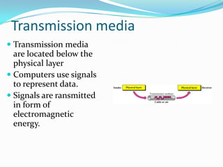
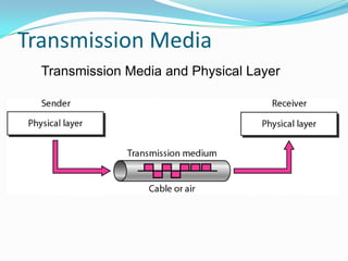
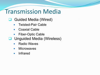
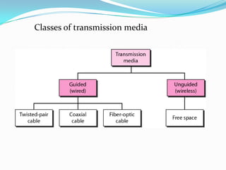
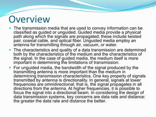

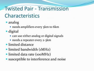
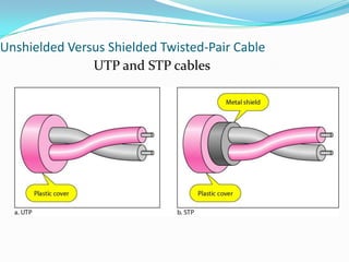
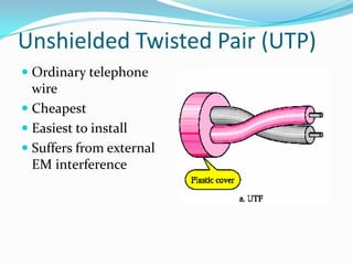

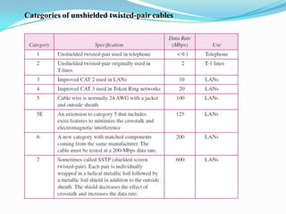
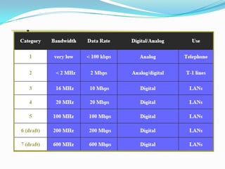
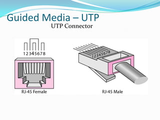
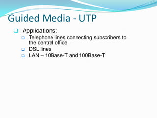

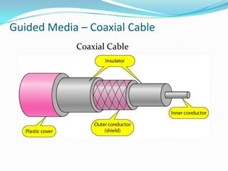
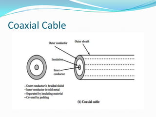
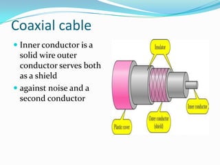
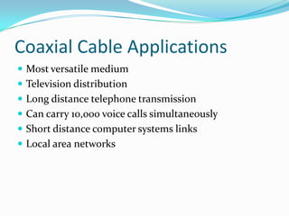
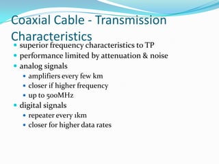
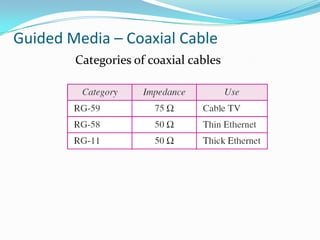
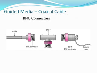
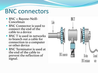
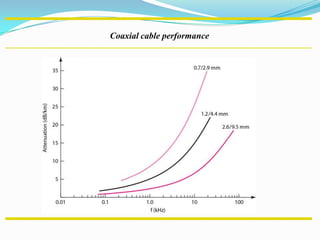
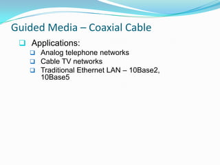
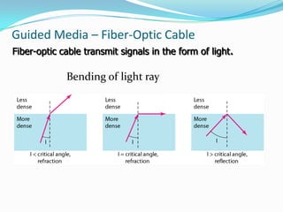
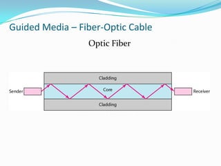
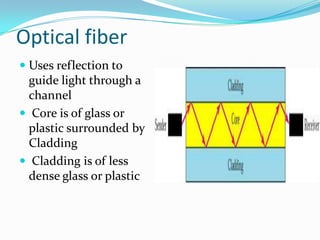
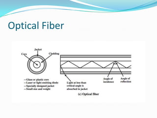
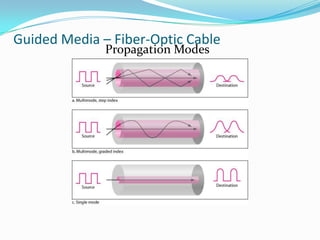
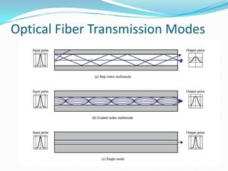
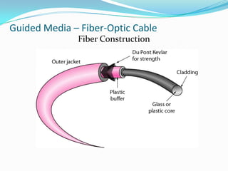

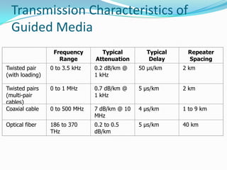
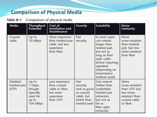
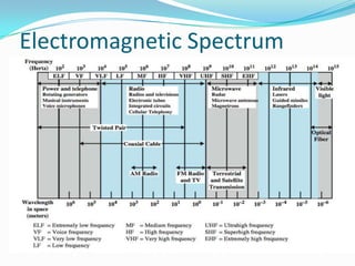
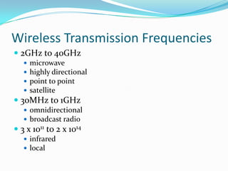
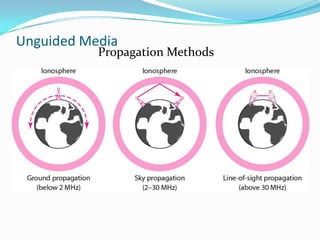
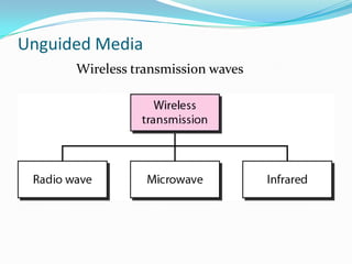
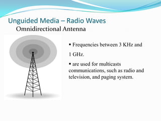
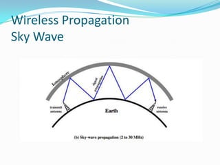
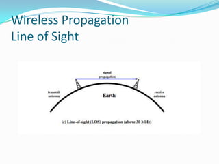
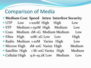

This document discusses different types of transmission media used to transmit signals and data in communication networks. It describes guided media such as twisted pair cable, coaxial cable, and fiber optic cable, which provide a physical path for signal propagation. It also covers unguided or wireless media that transmit signals through air using radio waves, microwaves, or infrared. The key characteristics, applications, and performance of each transmission medium are outlined.


![Chapter-2 Communiction media [Autosaved].ppt](https://cdn.slidesharecdn.com/ss_thumbnails/chapter-2communictionmediaautosaved-260117143116-9787c933-thumbnail.jpg?width=640&height=640&fit=bounds)