Downloaded 4,779 times


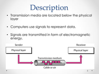
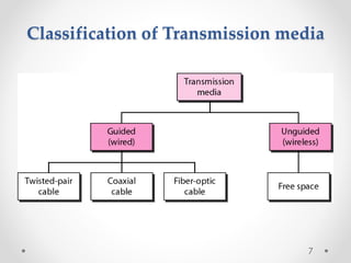
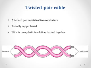
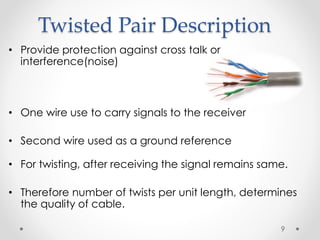
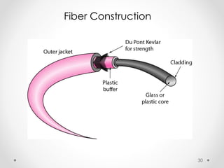
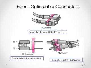
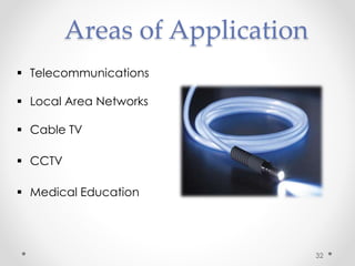
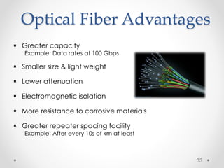
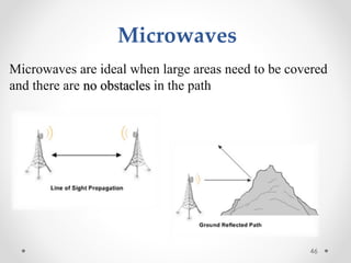
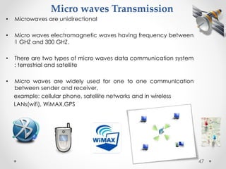
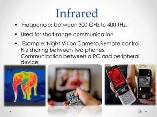


This document discusses different types of transmission media used for data communication. It describes guided media such as twisted pair cables, coaxial cables, and fiber optic cables. It also covers unguided or wireless media such as radio waves, microwaves, and infrared. For each medium, it provides details on their characteristics, applications, advantages and disadvantages. The document aims to classify and explain the basic concepts of different transmission media and their use in data communication networks.


![Chapter-2 Communiction media [Autosaved].ppt](https://cdn.slidesharecdn.com/ss_thumbnails/chapter-2communictionmediaautosaved-260117143116-9787c933-thumbnail.jpg?width=640&height=640&fit=bounds)