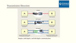
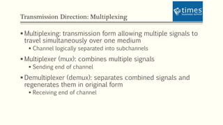
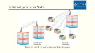
ADVANCE COMPUTER NETWORK AND SECURITY
Session By:
Dr.(h.c) Pravin Madalia Parmar
BCA, MCA, MCP, MCTS, PDM, Ph.D (Honorary Causa)
Communication Media and Data Transmission
Objectives
 Explain basic data transmission concepts,
including full duplexing, attenuation, and noise
 Describe the physical characteristics of coaxial
cable, STP, UTP, and fiber-optic media
 Compare the benefits and limitations of different
networking media
 Identify the best practices for cabling buildings
and work areas
 Specify the characteristics of popular wireless
transmission methods, including 802.11, infrared,
and Bluetooth
Transmission Basics
 In data networking, transmit means to issue signals to the network medium
 Transmission refers to either the process of transmitting or the progress of signals
after they have been transmitted
Analog and Digital Signals
 Information transmitted via analog or digital
signals
 Signal strength proportional to voltage
 In analog signals, voltage varies continuously and
appears as a wavy line when graphed over time
 Wave’s amplitude is a measure of its strength
 Frequency: number of times wave’s amplitude cycles
from starting point, through highest amplitude and
lowest amplitude, back to starting point over a fixed
period of time
 Measured in Hz
Analog and Digital Signals (continued)
 Wavelength: distance between corresponding points on a
wave’s cycle
 Phase: progress of a wave over time in relationship to a
fixed point
 Analog transmission susceptible to transmission flaws such
as noise
 Digital signals composed of pulses of precise, positive
voltages and zero voltages
 Positive voltage represents 1
 Zero voltage represents 0
Analog and Digital Signals (continued)
 Binary system: uses 1s and 0s to represent information
 Easy to convert between binary and decimal
 Bit: a single binary signal
 Byte: 8 bits
 Typically represents one piece of information
 Overhead: describes non-data information that must accompany data for a signal to
be properly routed and interpreted
Data Modulation
A carrier wave modified through frequency modulation
Transmission Direction:
 Simplex transmission: signals may travel in only one
direction
 Half-duplex transmission: signals may travel in both
directions over a medium
 Only one direction at a time
 Full-duplex or duplex: signals free to travel in both directions
over a medium simultaneously
 Used on data networks
 Channel: distinct communication path between nodes
 May be separated logically or physically
Transmission Direction
Simplex, half-duplex, and full-duplex communication
Transmission Direction: Multiplexing
 Multiplexing: transmission form allowing multiple signals to
travel simultaneously over one medium
 Channel logically separated into subchannels
 Multiplexer (mux): combines multiple signals
 Sending end of channel
 Demultiplexer (demux): separates combined signals and
regenerates them in original form
 Receiving end of channel
Relationships Between Nodes
Point-to-point versus broadcast transmission
Throughput and Bandwidth
 Throughput: measure of amount of data transmitted during given
time period
 Bandwidth: difference between highest and lowest frequencies that a
medium can transmit
Baseband and Broadband
 Baseband: digital signals sent through direct current (DC) pulses applied to a wire
 Requires exclusive use of wire’s capacity
 Baseband systems can transmit one signal at a time
 Ethernet
 Broadband: signals modulated as radiofrequency (RF) analog waves that use
different frequency ranges
 Does not encode information as digital pulses
Transmission Flaws: Noise
 electromagnetic interference (EMI): waves
emanating from electrical devices or cables
 radiofrequency interference (RFI):
electromagnetic interference caused by
radiowaves
 Crosstalk: signal traveling on a wire or cable
infringes on signal traveling over adjacent wire or
cable
 Certain amount of signal noise is unavoidable
 All forms of noise measured in decibels (dB)
Attenuation
A digital signal distorted by noise and then repeated
An analog signal distorted by noise and then amplified
Latency
 Delay between transmission and receipt of a signal
 Many possible causes:
 Cable length
 Intervening connectivity device (e.g., modems and routers)
 Round trip time (RTT): Time for packets to go from sender to
receiver and back
 Cabling rated for maximum number of connected network
segments
 Transmission methods assigned maximum segment lengths
Common Media Characteristics: Throughput
 Probably most significant factor in choosing transmission
method
 Limited by signaling and multiplexing techniques used in
given transmission method
 Transmission methods using fiber-optic cables achieve
faster throughput than those using copper or wireless
connections
 Noise and devices connected to transmission medium can
limit throughput
Cost
 Many variables can influence final cost of implementing specific type of media:
 Cost of installation
 Cost of new infrastructure versus reusing existing infrastructure
 Cost of maintenance and support
 Cost of a lower transmission rate affecting productivity
 Cost of obsolescence
Size and Scalability
 Three specifications determine size and scalability of networking media:
 Maximum nodes per segment
 Depends on attenuation and latency
 Maximum segment length
 Depends on attenuation, latency, and segment type
 Populated segment contains end nodes
 Maximum network length
 Sum of network’s segment lengths
Connectors and Media Converters
 Connectors: pieces of hardware connecting wire to network device
 Every networking medium requires specific kind of connector
 Media converter: hardware enabling networks or segments running on different
media to interconnect and exchange signals
 Type of transceiver
 Device that transmits and receives signals
Noise Immunity
 Some types of media are more susceptible to noise than others
 Fiber-optic cable least susceptible
 Install cabling away from powerful electromagnetic forces
 May need to use metal conduit to contain and protect cabling
 Possible to use antinoise algorithms
Coaxial Cable
 High resistance to noise; expensive
 Impedance: resistance that contributes to controlling signal (expressed in ohms)
 Thickwire Ethernet (Thicknet): original Ethernet medium
 10BASE-5 Ethernet
 Thin Ethernet (Thinnet): more flexible and easier to handle and install than Thicknet
 10BASE-2 Ethernet
Twisted-Pair Cable
 Color-coded pairs of insulated copper wires twisted together
 Twist ratio: twists per meter or foot
 Higher twist ratio reduces crosstalk and increases attenuation
 TIA/EIA 568 standard divides twisted-pair wiring into several categories
 Level 1 or CAT 3, 4, 5, 5e, 6, 6e, 7
 Most common form of cabling found on LANs today
STP (Shielded Twisted-Pair)
UTP (Unshielded Twisted-Pair)
 Less expensive, less resistant to noise than STP
 Categories:
 CAT 3 (Category 3): up to 10 Mbps of data
 CAT 4 (Category 4): 16 Mbps throughput
 CAT 5 (Category 5): up to 1000 Mbps throughput
 CAT 5e (Enhanced Category 5): higher twist ratio
 CAT 6 (Category 6): six times the throughput of
CAT 5
 CAT 6e (Enhanced Category 6): reduced attenuation and crosstalk
 CAT 7 (Category 7): signal rates up to 1 GHz
Comparing STP and UTP
 Throughput: STP and UTP can both transmit data at 10,
100, and 1000 Mbps
 Depending on grade of cabling and transmission method used
 Cost: STP usually more expensive than UTP
 Connector: Both use RJ-45 and RJ-11
 Noise Immunity: STP more noise-resistant
 Size and scalability: Max segment length for both is 100 m
on 10BASE-T and 100BASE-T networks
 Maximum of 1024 nodes
10BASE-T
 Fault tolerance: capacity for component or system to continue functioning despite
damage or partial malfunction
 5-4-3 rule of networking: between two communicating nodes, network cannot
contain more than five network segments connected by four repeating devices, and
no more than three of the segments may be populated
100BASE-T (Fast Ethernet)
100BASE-T network
Fiber-Optic Cable
 Contains glass or plastic fibers at core surrounded by layer of glass
or plastic cladding
 Reflects light back to core
SMF (Single-mode Fiber)
 Narrow core through which laser-generated light travels over one
path, reflecting very little
 Accommodates high bandwidths and long distances
 Expensive
MMF (Multimode Fiber)
 Benefits over copper cabling:
 Nearly unlimited throughput
 Very high resistance to noise
 Excellent security
 Ability to carry signals for much longer distances before requiring repeaters than copper cable
 Industry standard for high-speed networking
MMF (continued)
 Throughput: transmission rates exceed 10 Gigabits per
second
 Cost: most expensive transmission medium
 Connector: 10 different types of connectors
 Typically use ST or SC connectors
 Noise immunity: unaffected by EMI
 Size and scalability: segment lengths vary from
150 to 40,000 meters
 Optical loss: degradation of light signal after it travels a certain
distance away from its source
Summary of Physical Layer Standards
Summary of Physical Layer Standards (continued)
Cable Design and Management
 Cable plant: hardware making up enterprise-wide cabling
system
 Structured cabling: TIA/EIA’s 568 Commercial Building
Wiring Standard
 Entrance facilities point where building’s internal cabling plant
begins
 Demarcation point: division between service carrier’s network and internal
network
 Backbone wiring: interconnection between telecommunications
closets, equipment rooms, and entrance facilities
Cable Design and Management (continued)
 Structured cabling (continued):
 Equipment room: location of significant networking hardware, such
as servers and mainframe hosts
 Telecommunications closet: contains connectivity for groups of
workstations in area, plus cross connections to equipment rooms
 Horizontal wiring: wiring connecting workstations to closest
telecommunications closet
 Work area: encompasses all patch cables and horizontal wiring
necessary to connect workstations, printers, and other network
devices from NICs to telecommunications closet
Installing Cable
 Many network problems can be traced to poor cable
installation techniques
 Two methods of inserting UTP twisted pairs into RJ-45
plugs: TIA/EIA 568A and TIA/EIA 568B
 Straight-through cable allows signals to pass “straight
through” between terminations
 Crossover cable: termination locations of transmit and
receive wires on one end of cable reversed
Wireless Transmission
 Networks that transmit signals through the atmosphere via infrared or RF waves are
known as wireless networks or wireless LANs (WLANs)
The Wireless Spectrum
Characteristics of Wireless Transmission
Figure 3-38: Wireless transmission and reception
Antennas
 Radiation pattern describes relative strength over three-
dimensional area of all electromagnetic energy the antenna
sends or receives
 Directional antenna issues wireless signals along a single
direction
 Omnidirectional antenna issues and receives wireless
signals with equal strength and clarity in all directions
 Range: geographical area an antenna or wireless system
can reach
Signal Propagation
Figure 3-39: Multipath signal propagation
Signal Degradation
 Fading: change in signal strength resulting from electromagnetic energy being
scattered, reflected, or diffracted after being issued by transmitter
 Wireless signals experience attenuation
 May be amplified and repeated
 Interference is significant problem for wireless communications
 Atmosphere saturated with electromagnetic waves
Narrowband, Broadband, and Spread Spectrum Signals
 Narrowband: transmitter concentrates signal energy at
single frequency or in very small range of frequencies
 Broadband: uses relatively wide band of wireless spectrum
 Offers higher throughputs
 Spread spectrum: use of multiple frequencies to transmit a
signal
 Frequency hopping spread spectrum (FHSS)
 Direct sequence spread spectrum (DSSS)
Fixed versus Mobile
 Fixed wireless system: locations of transmitter and receiver do not move
 Point-to-point link
 Efficient use of signal energy
 Mobile wireless system: receiver can be located anywhere within transmitter’s range
 More flexible
Infrared Transmission
 Transmitted by frequencies in the 300-GHz to 300,000-GHz range
 Most often used for communications between devices in same room
 Relies on the devices being close to each other
 May require line-of-sight path
 Throughput rivals fiber-optics
Summary
 Information can be transmitted via two methods: analog
or digital
 In multiplexing, the single medium is logically separated
into multiple channels, or subchannels
 Throughput is the amount of data that the medium can
transmit during a given period of time
 Baseband is a form of transmission in which digital
signals are sent through direct current pulses applied to
the wire
 Noise is interference that distorts an analog or digital
signal
Summary (continued)
 Analog and digital signals may suffer attenuation
 Cable length contributes to latency, as does the
presence of any intervening connectivity device
 Coaxial cable consists of a central copper core
surrounded by a plastic insulator, a braided
metal shielding, and an outer plastic cover
(sheath)
 Twisted-pair cable consists of color-coded pairs
of insulated copper wires
 There are two types of twisted-pair cables: STP
and UTP
Summary (continued)
 There are a number of Physical layer specifications for
Ethernet networks
 Fiber-optic cable provides the benefits of very high
throughput, very high resistance to noise, and excellent
security
 Fiber cable variations fall into two categories: single-mode
and multimode
 Structured cabling is based on a hierarchical design that
divides cabling into six subsystems
Summary (continued)
 The best practice for installing cable is to follow the TIA/EIA 568 specifications and
the manufacturer’s recommendations
 Wireless transmission requires an antenna connected to a transceiver
 Infrared transmission can be used for short-distance transmissions
THANK YOU
Contact:
Mobile: +91 98799 33475, Email: pravin@aequitas-infotech.com

Transmission media

  • 1.
    ADVANCE COMPUTER NETWORKAND SECURITY Session By: Dr.(h.c) Pravin Madalia Parmar BCA, MCA, MCP, MCTS, PDM, Ph.D (Honorary Causa) Communication Media and Data Transmission
  • 2.
    Objectives  Explain basicdata transmission concepts, including full duplexing, attenuation, and noise  Describe the physical characteristics of coaxial cable, STP, UTP, and fiber-optic media  Compare the benefits and limitations of different networking media  Identify the best practices for cabling buildings and work areas  Specify the characteristics of popular wireless transmission methods, including 802.11, infrared, and Bluetooth
  • 3.
    Transmission Basics  Indata networking, transmit means to issue signals to the network medium  Transmission refers to either the process of transmitting or the progress of signals after they have been transmitted
  • 4.
    Analog and DigitalSignals  Information transmitted via analog or digital signals  Signal strength proportional to voltage  In analog signals, voltage varies continuously and appears as a wavy line when graphed over time  Wave’s amplitude is a measure of its strength  Frequency: number of times wave’s amplitude cycles from starting point, through highest amplitude and lowest amplitude, back to starting point over a fixed period of time  Measured in Hz
  • 5.
    Analog and DigitalSignals (continued)  Wavelength: distance between corresponding points on a wave’s cycle  Phase: progress of a wave over time in relationship to a fixed point  Analog transmission susceptible to transmission flaws such as noise  Digital signals composed of pulses of precise, positive voltages and zero voltages  Positive voltage represents 1  Zero voltage represents 0
  • 6.
    Analog and DigitalSignals (continued)  Binary system: uses 1s and 0s to represent information  Easy to convert between binary and decimal  Bit: a single binary signal  Byte: 8 bits  Typically represents one piece of information  Overhead: describes non-data information that must accompany data for a signal to be properly routed and interpreted
  • 7.
    Data Modulation A carrierwave modified through frequency modulation
  • 8.
    Transmission Direction:  Simplextransmission: signals may travel in only one direction  Half-duplex transmission: signals may travel in both directions over a medium  Only one direction at a time  Full-duplex or duplex: signals free to travel in both directions over a medium simultaneously  Used on data networks  Channel: distinct communication path between nodes  May be separated logically or physically
  • 9.
    Transmission Direction Simplex, half-duplex,and full-duplex communication
  • 10.
    Transmission Direction: Multiplexing Multiplexing: transmission form allowing multiple signals to travel simultaneously over one medium  Channel logically separated into subchannels  Multiplexer (mux): combines multiple signals  Sending end of channel  Demultiplexer (demux): separates combined signals and regenerates them in original form  Receiving end of channel
  • 11.
    Relationships Between Nodes Point-to-pointversus broadcast transmission
  • 12.
    Throughput and Bandwidth Throughput: measure of amount of data transmitted during given time period  Bandwidth: difference between highest and lowest frequencies that a medium can transmit
  • 13.
    Baseband and Broadband Baseband: digital signals sent through direct current (DC) pulses applied to a wire  Requires exclusive use of wire’s capacity  Baseband systems can transmit one signal at a time  Ethernet  Broadband: signals modulated as radiofrequency (RF) analog waves that use different frequency ranges  Does not encode information as digital pulses
  • 14.
    Transmission Flaws: Noise electromagnetic interference (EMI): waves emanating from electrical devices or cables  radiofrequency interference (RFI): electromagnetic interference caused by radiowaves  Crosstalk: signal traveling on a wire or cable infringes on signal traveling over adjacent wire or cable  Certain amount of signal noise is unavoidable  All forms of noise measured in decibels (dB)
  • 15.
    Attenuation A digital signaldistorted by noise and then repeated An analog signal distorted by noise and then amplified
  • 16.
    Latency  Delay betweentransmission and receipt of a signal  Many possible causes:  Cable length  Intervening connectivity device (e.g., modems and routers)  Round trip time (RTT): Time for packets to go from sender to receiver and back  Cabling rated for maximum number of connected network segments  Transmission methods assigned maximum segment lengths
  • 17.
    Common Media Characteristics:Throughput  Probably most significant factor in choosing transmission method  Limited by signaling and multiplexing techniques used in given transmission method  Transmission methods using fiber-optic cables achieve faster throughput than those using copper or wireless connections  Noise and devices connected to transmission medium can limit throughput
  • 18.
    Cost  Many variablescan influence final cost of implementing specific type of media:  Cost of installation  Cost of new infrastructure versus reusing existing infrastructure  Cost of maintenance and support  Cost of a lower transmission rate affecting productivity  Cost of obsolescence
  • 19.
    Size and Scalability Three specifications determine size and scalability of networking media:  Maximum nodes per segment  Depends on attenuation and latency  Maximum segment length  Depends on attenuation, latency, and segment type  Populated segment contains end nodes  Maximum network length  Sum of network’s segment lengths
  • 20.
    Connectors and MediaConverters  Connectors: pieces of hardware connecting wire to network device  Every networking medium requires specific kind of connector  Media converter: hardware enabling networks or segments running on different media to interconnect and exchange signals  Type of transceiver  Device that transmits and receives signals
  • 21.
    Noise Immunity  Sometypes of media are more susceptible to noise than others  Fiber-optic cable least susceptible  Install cabling away from powerful electromagnetic forces  May need to use metal conduit to contain and protect cabling  Possible to use antinoise algorithms
  • 22.
    Coaxial Cable  Highresistance to noise; expensive  Impedance: resistance that contributes to controlling signal (expressed in ohms)  Thickwire Ethernet (Thicknet): original Ethernet medium  10BASE-5 Ethernet  Thin Ethernet (Thinnet): more flexible and easier to handle and install than Thicknet  10BASE-2 Ethernet
  • 23.
    Twisted-Pair Cable  Color-codedpairs of insulated copper wires twisted together  Twist ratio: twists per meter or foot  Higher twist ratio reduces crosstalk and increases attenuation  TIA/EIA 568 standard divides twisted-pair wiring into several categories  Level 1 or CAT 3, 4, 5, 5e, 6, 6e, 7  Most common form of cabling found on LANs today
  • 24.
  • 25.
    UTP (Unshielded Twisted-Pair) Less expensive, less resistant to noise than STP  Categories:  CAT 3 (Category 3): up to 10 Mbps of data  CAT 4 (Category 4): 16 Mbps throughput  CAT 5 (Category 5): up to 1000 Mbps throughput  CAT 5e (Enhanced Category 5): higher twist ratio  CAT 6 (Category 6): six times the throughput of CAT 5  CAT 6e (Enhanced Category 6): reduced attenuation and crosstalk  CAT 7 (Category 7): signal rates up to 1 GHz
  • 26.
    Comparing STP andUTP  Throughput: STP and UTP can both transmit data at 10, 100, and 1000 Mbps  Depending on grade of cabling and transmission method used  Cost: STP usually more expensive than UTP  Connector: Both use RJ-45 and RJ-11  Noise Immunity: STP more noise-resistant  Size and scalability: Max segment length for both is 100 m on 10BASE-T and 100BASE-T networks  Maximum of 1024 nodes
  • 27.
    10BASE-T  Fault tolerance:capacity for component or system to continue functioning despite damage or partial malfunction  5-4-3 rule of networking: between two communicating nodes, network cannot contain more than five network segments connected by four repeating devices, and no more than three of the segments may be populated
  • 28.
  • 29.
    Fiber-Optic Cable  Containsglass or plastic fibers at core surrounded by layer of glass or plastic cladding  Reflects light back to core
  • 30.
    SMF (Single-mode Fiber) Narrow core through which laser-generated light travels over one path, reflecting very little  Accommodates high bandwidths and long distances  Expensive
  • 31.
    MMF (Multimode Fiber) Benefits over copper cabling:  Nearly unlimited throughput  Very high resistance to noise  Excellent security  Ability to carry signals for much longer distances before requiring repeaters than copper cable  Industry standard for high-speed networking
  • 32.
    MMF (continued)  Throughput:transmission rates exceed 10 Gigabits per second  Cost: most expensive transmission medium  Connector: 10 different types of connectors  Typically use ST or SC connectors  Noise immunity: unaffected by EMI  Size and scalability: segment lengths vary from 150 to 40,000 meters  Optical loss: degradation of light signal after it travels a certain distance away from its source
  • 33.
    Summary of PhysicalLayer Standards
  • 34.
    Summary of PhysicalLayer Standards (continued)
  • 35.
    Cable Design andManagement  Cable plant: hardware making up enterprise-wide cabling system  Structured cabling: TIA/EIA’s 568 Commercial Building Wiring Standard  Entrance facilities point where building’s internal cabling plant begins  Demarcation point: division between service carrier’s network and internal network  Backbone wiring: interconnection between telecommunications closets, equipment rooms, and entrance facilities
  • 36.
    Cable Design andManagement (continued)  Structured cabling (continued):  Equipment room: location of significant networking hardware, such as servers and mainframe hosts  Telecommunications closet: contains connectivity for groups of workstations in area, plus cross connections to equipment rooms  Horizontal wiring: wiring connecting workstations to closest telecommunications closet  Work area: encompasses all patch cables and horizontal wiring necessary to connect workstations, printers, and other network devices from NICs to telecommunications closet
  • 37.
    Installing Cable  Manynetwork problems can be traced to poor cable installation techniques  Two methods of inserting UTP twisted pairs into RJ-45 plugs: TIA/EIA 568A and TIA/EIA 568B  Straight-through cable allows signals to pass “straight through” between terminations  Crossover cable: termination locations of transmit and receive wires on one end of cable reversed
  • 38.
    Wireless Transmission  Networksthat transmit signals through the atmosphere via infrared or RF waves are known as wireless networks or wireless LANs (WLANs)
  • 39.
  • 40.
    Characteristics of WirelessTransmission Figure 3-38: Wireless transmission and reception
  • 41.
    Antennas  Radiation patterndescribes relative strength over three- dimensional area of all electromagnetic energy the antenna sends or receives  Directional antenna issues wireless signals along a single direction  Omnidirectional antenna issues and receives wireless signals with equal strength and clarity in all directions  Range: geographical area an antenna or wireless system can reach
  • 42.
    Signal Propagation Figure 3-39:Multipath signal propagation
  • 43.
    Signal Degradation  Fading:change in signal strength resulting from electromagnetic energy being scattered, reflected, or diffracted after being issued by transmitter  Wireless signals experience attenuation  May be amplified and repeated  Interference is significant problem for wireless communications  Atmosphere saturated with electromagnetic waves
  • 44.
    Narrowband, Broadband, andSpread Spectrum Signals  Narrowband: transmitter concentrates signal energy at single frequency or in very small range of frequencies  Broadband: uses relatively wide band of wireless spectrum  Offers higher throughputs  Spread spectrum: use of multiple frequencies to transmit a signal  Frequency hopping spread spectrum (FHSS)  Direct sequence spread spectrum (DSSS)
  • 45.
    Fixed versus Mobile Fixed wireless system: locations of transmitter and receiver do not move  Point-to-point link  Efficient use of signal energy  Mobile wireless system: receiver can be located anywhere within transmitter’s range  More flexible
  • 46.
    Infrared Transmission  Transmittedby frequencies in the 300-GHz to 300,000-GHz range  Most often used for communications between devices in same room  Relies on the devices being close to each other  May require line-of-sight path  Throughput rivals fiber-optics
  • 47.
    Summary  Information canbe transmitted via two methods: analog or digital  In multiplexing, the single medium is logically separated into multiple channels, or subchannels  Throughput is the amount of data that the medium can transmit during a given period of time  Baseband is a form of transmission in which digital signals are sent through direct current pulses applied to the wire  Noise is interference that distorts an analog or digital signal
  • 48.
    Summary (continued)  Analogand digital signals may suffer attenuation  Cable length contributes to latency, as does the presence of any intervening connectivity device  Coaxial cable consists of a central copper core surrounded by a plastic insulator, a braided metal shielding, and an outer plastic cover (sheath)  Twisted-pair cable consists of color-coded pairs of insulated copper wires  There are two types of twisted-pair cables: STP and UTP
  • 49.
    Summary (continued)  Thereare a number of Physical layer specifications for Ethernet networks  Fiber-optic cable provides the benefits of very high throughput, very high resistance to noise, and excellent security  Fiber cable variations fall into two categories: single-mode and multimode  Structured cabling is based on a hierarchical design that divides cabling into six subsystems
  • 50.
    Summary (continued)  Thebest practice for installing cable is to follow the TIA/EIA 568 specifications and the manufacturer’s recommendations  Wireless transmission requires an antenna connected to a transceiver  Infrared transmission can be used for short-distance transmissions
  • 51.
    THANK YOU Contact: Mobile: +9198799 33475, Email: pravin@aequitas-infotech.com