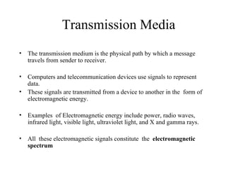
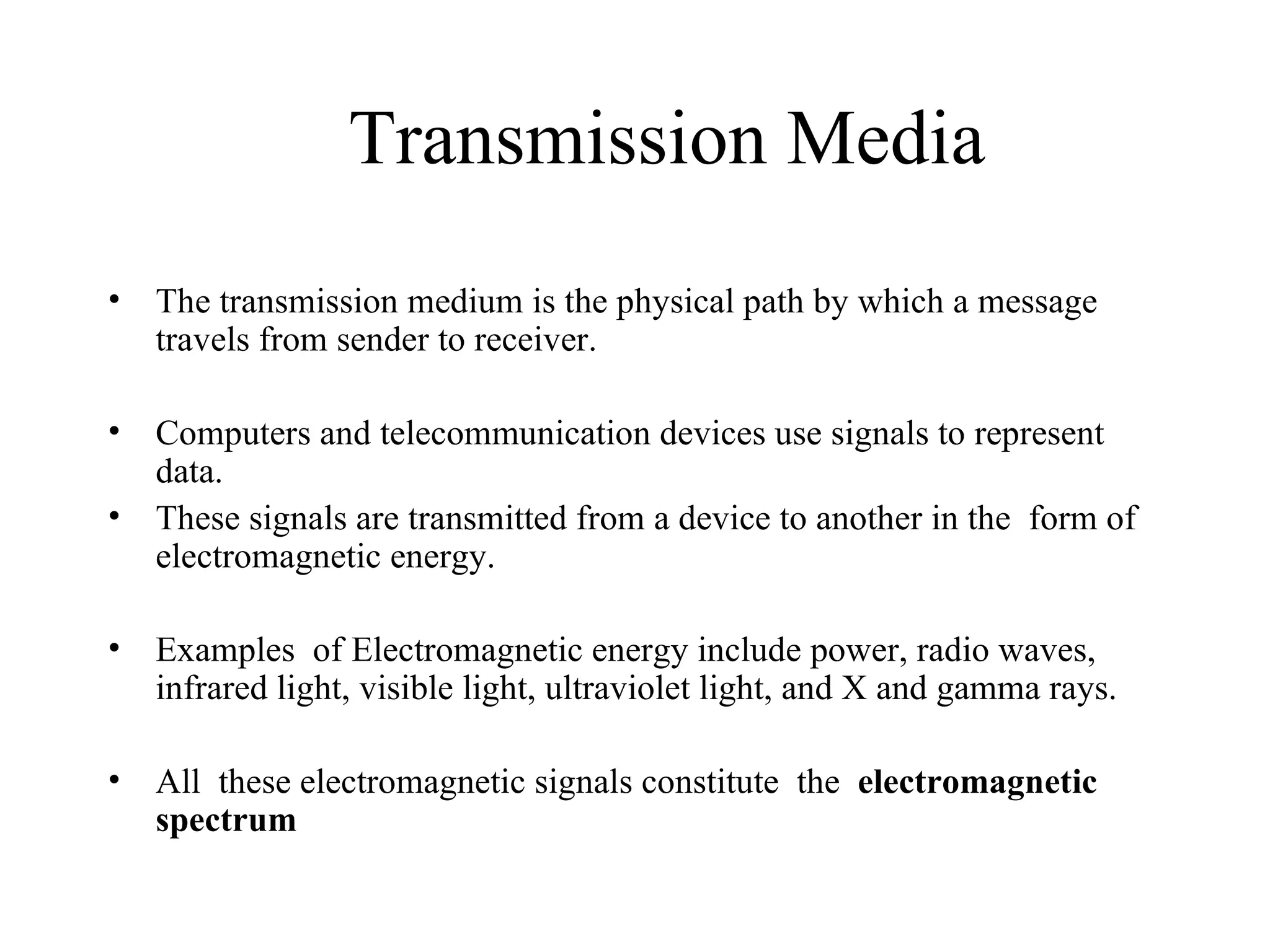
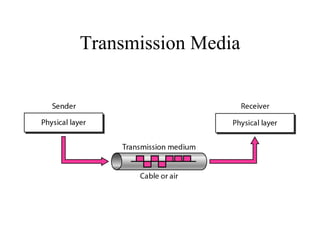
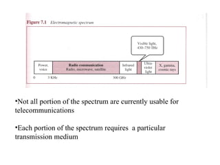
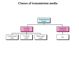
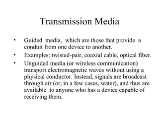
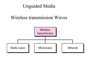
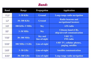
Transmission Media
•   The transmission medium is the physical path by which a message
    travels from sender to receiver.

•   Computers and telecommunication devices use signals to represent
    data.
•   These signals are transmitted from a device to another in the form of
    electromagnetic energy.

•   Examples of Electromagnetic energy include power, radio waves,
    infrared light, visible light, ultraviolet light, and X and gamma rays.

•   All these electromagnetic signals constitute the electromagnetic
    spectrum
Transmission Media
•Not all portion of the spectrum are currently usable for
telecommunications

•Each portion of the spectrum requires a particular
transmission medium
•   Signals of low frequency (like voice
    signals) are generally transmitted as
    current over metal cables. It is not
    possible to transmit visible light over
    metal cables, for this class of signals is
    necessary to use a different media, for
    example fiber-optic cable.
Classes of transmission media
Transmission Media
•   Guided media, which are those that provide a
    conduit from one device to another.
•   Examples: twisted-pair, coaxial cable, optical fiber.
•   Unguided media (or wireless communication)
    transport electromagnetic waves without using a
    physical conductor. Instead, signals are broadcast
    through air (or, in a few cases, water), and thus are
    available to anyone who has a device capable of
    receiving them.
Guided Media


There are three categories of guided media:
   1. Twisted-pair cable
   2. Coaxial cable
   3. Fiber-optic cable
Twisted-pair cable


•   Twisted pair consists of two
    conductors (normally copper),
    each with its own plastic
    insulation, twisted together.
•   Twisted-pair cable comes in
    two forms: unshielded and
    shielded
•   The twisting helps to reduce the
    interference (noise) and
    crosstalk.
Twisted-pair cable

•   One of the wires carries signal, the other is used only as a ground
    reference.
•   The receiver uses the difference b/w the two levels.
•   Twisting increases the probability that both wires are effected by the
    noise in the same manner, thus the difference at the receiver remains
    same.
•   Therefore, number of twists per unit length determines the quality of
    the cable.
UTP and STP
Unshielded Twisted-pair (UTP) cable
•   Any medium can transmit only
    a fixed range of frequencies!
•   UTP cable is the most common
    type of telecommunication
    medium in use today.

•   The range is suitable for
    transmitting both data and
    video.
•   Advantages of UTP are its cost
    and ease of use. UTP is cheap,
    flexible, and easy to install.
The Electronic Industries Association (EIA) has
    developed standards to grade UTP.
2. Category 1. The basic twisted-pair cabling used in
    telephone systems. This level of quality is fine for
    voice but inadequate for data transmission.
3. Category 2. This category is suitable for voice and
    data transmission of up to 2Mbps.
4. Category 3.This category is suitable for data
    transmission of up to 10 Mbps. It is now the
    standard cable for most telephone systems.
5. Category 4. This category is suitable for data
    transmission of up to 20 Mbps.
6. Category 5. This category is suitable for data
    transmission of up to 100 Mbps.
UTP connectors

The most common UTP connector is RJ45 (RJ stands for
Registered Jack).
Shielded Twisted (STP) Cable

•   STP cable has a metal foil or
    braided-mesh covering that
    enhances each pair of insulated
    conductors.
•   The metal casing prevents the
    penetration of electromagnetic
    noise.
•   Materials and manufacturing
    requirements make STP more
    expensive than UTP but less
    susceptible to noise.
Applications

• Twisted-pair cables are used in telephones lines to provide
  voice and data channels.
• Local area networks, such as 10Base-T and 100Base-T,
  also used UTP cables.
Coaxial Cable
Coaxial Cable (or coax)

•   Coaxial cable carries signals of
    higher frequency ranges than
    twisted-pair cable.

• Coaxial Cable standards:
RG-8, RG-9, RG-11 are
used in thick Ethernet
RG-58 Used in thin Ethernet
RG-59 Used for TV
BNC connectors

•To connect coaxial cable to devices, it is necessary to use
coaxial connectors. The most common type of connector is the
Bayone-Neill-Concelman, or BNC, connectors. There are three
types: the BNC connector, the BNC T connector, the BNC
terminator.
Applications include cable TV networks, and some traditional
Ethernet LANs like 10Base-2, or 10-Base5.
Coaxial Cable Applications
•   Most versatile medium
•   Television distribution
•   Long distance telephone transmission
•   Can carry 10,000 voice calls simultaneously
•   Short distance computer systems links
•   Local area networks
Optical Fiber
• Metal cables transmit signals in the form of electric
  current.
• Optical fiber is made of glass or plastic and transmits
  signals in the form of light.
• Light, a form of electromagnetic energy, travels at
  300,000 Kilometers/second ( 186,000 miles/second), in a
  vacuum.
• The speed of the light depends on the density of the
  medium through which it is traveling ( the higher density,
  the slower the speed).
The Nature of the Light

• Light travels in a straight line as long as it is moving
  through a single uniform substance.

• If a ray of light traveling through one substance suddenly
  enters another (less or more dense) substance, its speed
  changes abruptly, causing the ray to change direction. This
  change is called refraction.
Refraction
Critical angle

•If the angle of incidence increases, so does the angle of
refraction.
•The critical angle is defined to be an angle of incidence for
which the angle of refraction is 90 degrees.
Reflection
•   When the angle of incidence
    becomes greater than the
    critical angle, a new
    phenomenon occurs called
    reflection.

•   Light no longer passes into the
    less dense medium at all.
Critical Angle
•   Optical fibers use reflection to guide light through a channel.
•   A glass or core is surrounded by a cladding of less dense glass or
    plastic. The difference in density of the two materials must be such
    that a beam of light moving through the core is reflected off the
    cladding instead of being into it.
•   Information is encoded onto a beam of light as a series of on-off
    flashes that represent 1 and 0 bits.
Fiber construction
Types of Optical Fiber
• There are two basic types of fiber: multimode fiber and
  single-mode fiber.

• Multimode fiber is best designed for short transmission
  distances, and is suited for use in LAN systems and video
  surveillance.

• Single-mode fiber is best designed for longer transmission
  distances, making it suitable for long-distance telephony
  and multichannel television broadcast systems.
Propagation Modes (Types of Optical Fiber )

•   Current technology supports
    two modes for propagating
    light along optical channels,
    each requiring fiber with
    different physical
    characteristics: Multimode
    and Single Mode.

•   Multimode, in turn, can be
    implemented in two forms:
    step-index or graded index.
• Multimode: In this case multiple beams from a
  light source move through the core in different
  paths.
• In multimode step-index fiber, the density of the
  core remains constant from the center to the
  edges. A beam of light moves through this
  constant density in a straight line until it reaches
  the interface of the core and cladding. At the
  interface there is an abrupt change to a lower
  density that alters the angle of the beam’s
  motion.
• In a multimode graded-index fiber the density is
  highest at the center of the core and decreases
  gradually to its lowest at the edge.
Propagation Modes
Light sources for optical fibers

•   The purpose of fiber-optic cable is to contain and
    direct a beam of light from source to target.
•   The sending device must be equipped with a light
    source and the receiving device with photosensitive
    cell (called a photodiode) capable of translating the
    received light into an electrical signal.
•   The light source can be either a light-emitting diode
    (LED) or an injection laser diode.
Fiber-optic cable connectors
The subscriber channel (SC) connector is used in cable TV. It uses
a push/pull locking system. The straight-tip (ST) connector is used
for connecting cable to networking devices. MT-RJ is a new
connector with the same size as RJ45.
Guided Media – Optical Fiber Cable
 Applications:
   Backbone networks – SONET
   Cable TV – backbone
   LAN
     100Base-FX network (Fast Ethernet)
     100Base-X
Advantages of Optical Fiber

• The major advantages offered by fiber-optic
  cable over twisted-pair and coaxial cable are
  noise resistance, less signal attenuation, and
  higher bandwidth.

• Noise Resistance: Because fiber-optic
  transmission uses light rather than electricity,
  noise is not a factor. External light, the only
  possible interference, is blocked from the
  channel by the outer jacket.
Advantages of Optical Fiber

• Less signal attenuation
Fiber-optic transmission distance is significantly greater than
   that of other guided media. A signal can run for miles
   without requiring regeneration.
• Higher bandwidth
Currently, data rates and bandwidth utilization over fiber-
   optic cable are limited not by the medium but by the signal
   generation and reception technology available.
Disadvantages of Optical Fiber

• The main disadvantages of fiber optics are cost,
  installation/maintenance, and fragility.
• Cost. Fiber-optic cable is expensive. Also, a laser light
  source can cost thousands of dollars, compared to
  hundreds of dollars for electrical signal generators.
• Installation/maintenance
• Fragility. Glass fiber is more easily broken than wire,
  making it less useful for applications where hardware
  portability is required.
Unguided Media

Wireless transmission Waves
Unguided Media

• Unguided media, or wireless communication, transport
  electromagnetic waves without using a physical conductor.
  Instead the signals are broadcast though air or water, and
  thus are available to anyone who has a device capable of
  receiving them.
• The section of the electromagnetic spectrum defined as
  radio communication is divided into eight ranges, called
  bands, each regulated by government authorities.
Propagation of Radio Waves

• Radio technology considers the earth as surrounded by two
  layers of atmosphere: the troposphere and the
  ionosphere.

• The troposphere is the portion of the atmosphere
  extending outward approximately 30 miles from the earth's
  surface.
• The troposphere contains what we generally think of as
  air. Clouds, wind, temperature variations, and weather in
  general occur in the troposphere.
• The ionosphere is the layer of the atmosphere above the
  troposphere but below space.
Propagation methods
• Ground propagation. In ground propagation, radio
  waves travel through the lowest portion of the
  atmosphere, hugging the earth. These low-frequency
  signals emanate in all directions from the transmitting
  antenna and follow the curvature of the planet. The
  distance depends on the power in the signal.
• In Sky propagation, higher-frequency radio waves
  radiate upward into the ionosphere where they are
  reflected back to earth. This type of transmission
  allows for greater distances with lower power output.

• In Line-of-Sight Propagation, very high frequency
  signals are transmitted in straight lines directly from
  antenna to antenna.
Bands
Band       Range       Propagation             Application

VLF      3–30 KHz        Ground        Long-range radio navigation
                                           Radio beacons and
LF      30–300 KHz       Ground
                                          navigational locators
MF     300 KHz–3 MHz       Sky                 AM radio
                                           Citizens band (CB),
HF       3–30 MHz          Sky
                                       ship/aircraft communication
                         Sky and               VHF TV,
VHF     30–300 MHz
                       line-of-sight           FM radio
                                        UHF TV, cellular phones,
UHF    300 MHz–3 GHz   Line-of-sight
                                            paging, satellite

SHF      3–30 GHz      Line-of-sight     Satellite communication

EHF     30–300 GHz     Line-of-sight   Long-range radio navigation
Radio waves Transmission
The Radio waves have frequencies between 3khz and1Ghz
Radio waves are Omni directional.
Radio waves can penetrate buildings easily, so that are widely use for
communication both indoors outdoors.
They also absorbed by rains
At high frequency, radio wave tends to travel in straight line.
Unguided Media – Radio Waves

              Omnidirectional Antenna
               Frequencies between 3
                KHz and 1 GHz.
               are used for multicasts
                communications, such as
                radio and television, and
                paging system.
Antennas
• An Antenna is a structure that is generally a metallic
  object, often a wire or group of wires, used to convert
  high frequency current into electromagnetic waves,
  and vice versa.
• transmission antenna
   – radio frequency energy from transmitter
   – converted to electromagnetic energy by antenna
   – radiated into surrounding environment
• reception antenna
   – electromagnetic energy impinging on antenna
   – converted to radio frequency electrical energy
   – fed to receiver
• same antenna is often used for both purposes
Micro waves Transmission

•   Micro waves electromagnetic waves having frequency between 1
    GHZ and 300 GHZ.
•   There are two types of micro waves data communication system :
    terrestrial and satellite
•   Micro waves are widely used for one to one communication between
    sender and receiver, cellular phone, satellite networks and in wireless
    LANs.
•   Microwaves are unidirectional.
Infrared
   Frequencies between 300 GHz to 400 THz.


 Used for short-range communication such as those
  between a PC and peripheral device.
Transmission Impairment
• Singnal travel through transmission media
  which are not perfect.The Imperfection
  causes signal impairment.
• What is sent is not what is received.
• Three causes of impairement are
  1)Attenuation,
  2)distortion
   3)noise.
Transmission Impairment
• Attenuation means a loss of energy.
• When a signal,simple or composite,travels
  through a medium,it loses some of its
  energy in overcoming the resistance of the
  medium.
• To compensate for this loss, amplifiers are
  used to amplify the signal.
Transmission Impairment
• To show that the signal has lost or gained
  strength,use the unit of the decibel.
• Decibel(dB) measures the relative strength
  of two signals or one signal at two different
  points.
• Decibel is negative if a signal is attenuated
  and positive if the signal is amplified.
Transmission Impairment
• Distortion means that the signal changes its
  form or shape.
• Distortion can occur in a composite signal
  made of different frequencies.
• Noise is another cause of impairement.
  Several types of noise ,such as thermal
  noise,induced noise,crosstalk may currupt
  the signal.

Dcunit4 transmission media

  • 1.
    Transmission Media • The transmission medium is the physical path by which a message travels from sender to receiver. • Computers and telecommunication devices use signals to represent data. • These signals are transmitted from a device to another in the form of electromagnetic energy. • Examples of Electromagnetic energy include power, radio waves, infrared light, visible light, ultraviolet light, and X and gamma rays. • All these electromagnetic signals constitute the electromagnetic spectrum
  • 2.
  • 3.
    •Not all portionof the spectrum are currently usable for telecommunications •Each portion of the spectrum requires a particular transmission medium
  • 4.
    Signals of low frequency (like voice signals) are generally transmitted as current over metal cables. It is not possible to transmit visible light over metal cables, for this class of signals is necessary to use a different media, for example fiber-optic cable.
  • 5.
  • 6.
    Transmission Media • Guided media, which are those that provide a conduit from one device to another. • Examples: twisted-pair, coaxial cable, optical fiber. • Unguided media (or wireless communication) transport electromagnetic waves without using a physical conductor. Instead, signals are broadcast through air (or, in a few cases, water), and thus are available to anyone who has a device capable of receiving them.
  • 7.
    Guided Media There arethree categories of guided media: 1. Twisted-pair cable 2. Coaxial cable 3. Fiber-optic cable
  • 8.
    Twisted-pair cable • Twisted pair consists of two conductors (normally copper), each with its own plastic insulation, twisted together. • Twisted-pair cable comes in two forms: unshielded and shielded • The twisting helps to reduce the interference (noise) and crosstalk.
  • 10.
    Twisted-pair cable • One of the wires carries signal, the other is used only as a ground reference. • The receiver uses the difference b/w the two levels. • Twisting increases the probability that both wires are effected by the noise in the same manner, thus the difference at the receiver remains same. • Therefore, number of twists per unit length determines the quality of the cable.
  • 11.
  • 12.
    Unshielded Twisted-pair (UTP)cable • Any medium can transmit only a fixed range of frequencies! • UTP cable is the most common type of telecommunication medium in use today. • The range is suitable for transmitting both data and video. • Advantages of UTP are its cost and ease of use. UTP is cheap, flexible, and easy to install.
  • 13.
    The Electronic IndustriesAssociation (EIA) has developed standards to grade UTP. 2. Category 1. The basic twisted-pair cabling used in telephone systems. This level of quality is fine for voice but inadequate for data transmission. 3. Category 2. This category is suitable for voice and data transmission of up to 2Mbps. 4. Category 3.This category is suitable for data transmission of up to 10 Mbps. It is now the standard cable for most telephone systems. 5. Category 4. This category is suitable for data transmission of up to 20 Mbps. 6. Category 5. This category is suitable for data transmission of up to 100 Mbps.
  • 14.
    UTP connectors The mostcommon UTP connector is RJ45 (RJ stands for Registered Jack).
  • 15.
    Shielded Twisted (STP)Cable • STP cable has a metal foil or braided-mesh covering that enhances each pair of insulated conductors. • The metal casing prevents the penetration of electromagnetic noise. • Materials and manufacturing requirements make STP more expensive than UTP but less susceptible to noise.
  • 16.
    Applications • Twisted-pair cablesare used in telephones lines to provide voice and data channels. • Local area networks, such as 10Base-T and 100Base-T, also used UTP cables.
  • 17.
  • 18.
    Coaxial Cable (orcoax) • Coaxial cable carries signals of higher frequency ranges than twisted-pair cable. • Coaxial Cable standards: RG-8, RG-9, RG-11 are used in thick Ethernet RG-58 Used in thin Ethernet RG-59 Used for TV
  • 19.
    BNC connectors •To connectcoaxial cable to devices, it is necessary to use coaxial connectors. The most common type of connector is the Bayone-Neill-Concelman, or BNC, connectors. There are three types: the BNC connector, the BNC T connector, the BNC terminator. Applications include cable TV networks, and some traditional Ethernet LANs like 10Base-2, or 10-Base5.
  • 20.
    Coaxial Cable Applications • Most versatile medium • Television distribution • Long distance telephone transmission • Can carry 10,000 voice calls simultaneously • Short distance computer systems links • Local area networks
  • 21.
    Optical Fiber • Metalcables transmit signals in the form of electric current. • Optical fiber is made of glass or plastic and transmits signals in the form of light. • Light, a form of electromagnetic energy, travels at 300,000 Kilometers/second ( 186,000 miles/second), in a vacuum. • The speed of the light depends on the density of the medium through which it is traveling ( the higher density, the slower the speed).
  • 22.
    The Nature ofthe Light • Light travels in a straight line as long as it is moving through a single uniform substance. • If a ray of light traveling through one substance suddenly enters another (less or more dense) substance, its speed changes abruptly, causing the ray to change direction. This change is called refraction.
  • 23.
  • 24.
    Critical angle •If theangle of incidence increases, so does the angle of refraction. •The critical angle is defined to be an angle of incidence for which the angle of refraction is 90 degrees.
  • 25.
    Reflection • When the angle of incidence becomes greater than the critical angle, a new phenomenon occurs called reflection. • Light no longer passes into the less dense medium at all.
  • 26.
  • 27.
    Optical fibers use reflection to guide light through a channel. • A glass or core is surrounded by a cladding of less dense glass or plastic. The difference in density of the two materials must be such that a beam of light moving through the core is reflected off the cladding instead of being into it. • Information is encoded onto a beam of light as a series of on-off flashes that represent 1 and 0 bits.
  • 28.
  • 29.
    Types of OpticalFiber • There are two basic types of fiber: multimode fiber and single-mode fiber. • Multimode fiber is best designed for short transmission distances, and is suited for use in LAN systems and video surveillance. • Single-mode fiber is best designed for longer transmission distances, making it suitable for long-distance telephony and multichannel television broadcast systems.
  • 30.
    Propagation Modes (Typesof Optical Fiber ) • Current technology supports two modes for propagating light along optical channels, each requiring fiber with different physical characteristics: Multimode and Single Mode. • Multimode, in turn, can be implemented in two forms: step-index or graded index.
  • 31.
    • Multimode: Inthis case multiple beams from a light source move through the core in different paths. • In multimode step-index fiber, the density of the core remains constant from the center to the edges. A beam of light moves through this constant density in a straight line until it reaches the interface of the core and cladding. At the interface there is an abrupt change to a lower density that alters the angle of the beam’s motion. • In a multimode graded-index fiber the density is highest at the center of the core and decreases gradually to its lowest at the edge.
  • 32.
  • 33.
    Light sources foroptical fibers • The purpose of fiber-optic cable is to contain and direct a beam of light from source to target. • The sending device must be equipped with a light source and the receiving device with photosensitive cell (called a photodiode) capable of translating the received light into an electrical signal. • The light source can be either a light-emitting diode (LED) or an injection laser diode.
  • 34.
    Fiber-optic cable connectors Thesubscriber channel (SC) connector is used in cable TV. It uses a push/pull locking system. The straight-tip (ST) connector is used for connecting cable to networking devices. MT-RJ is a new connector with the same size as RJ45.
  • 35.
    Guided Media –Optical Fiber Cable  Applications:  Backbone networks – SONET  Cable TV – backbone  LAN  100Base-FX network (Fast Ethernet)  100Base-X
  • 36.
    Advantages of OpticalFiber • The major advantages offered by fiber-optic cable over twisted-pair and coaxial cable are noise resistance, less signal attenuation, and higher bandwidth. • Noise Resistance: Because fiber-optic transmission uses light rather than electricity, noise is not a factor. External light, the only possible interference, is blocked from the channel by the outer jacket.
  • 37.
    Advantages of OpticalFiber • Less signal attenuation Fiber-optic transmission distance is significantly greater than that of other guided media. A signal can run for miles without requiring regeneration. • Higher bandwidth Currently, data rates and bandwidth utilization over fiber- optic cable are limited not by the medium but by the signal generation and reception technology available.
  • 38.
    Disadvantages of OpticalFiber • The main disadvantages of fiber optics are cost, installation/maintenance, and fragility. • Cost. Fiber-optic cable is expensive. Also, a laser light source can cost thousands of dollars, compared to hundreds of dollars for electrical signal generators. • Installation/maintenance • Fragility. Glass fiber is more easily broken than wire, making it less useful for applications where hardware portability is required.
  • 39.
  • 40.
    Unguided Media • Unguidedmedia, or wireless communication, transport electromagnetic waves without using a physical conductor. Instead the signals are broadcast though air or water, and thus are available to anyone who has a device capable of receiving them. • The section of the electromagnetic spectrum defined as radio communication is divided into eight ranges, called bands, each regulated by government authorities.
  • 42.
    Propagation of RadioWaves • Radio technology considers the earth as surrounded by two layers of atmosphere: the troposphere and the ionosphere. • The troposphere is the portion of the atmosphere extending outward approximately 30 miles from the earth's surface. • The troposphere contains what we generally think of as air. Clouds, wind, temperature variations, and weather in general occur in the troposphere. • The ionosphere is the layer of the atmosphere above the troposphere but below space.
  • 43.
  • 44.
    • Ground propagation.In ground propagation, radio waves travel through the lowest portion of the atmosphere, hugging the earth. These low-frequency signals emanate in all directions from the transmitting antenna and follow the curvature of the planet. The distance depends on the power in the signal. • In Sky propagation, higher-frequency radio waves radiate upward into the ionosphere where they are reflected back to earth. This type of transmission allows for greater distances with lower power output. • In Line-of-Sight Propagation, very high frequency signals are transmitted in straight lines directly from antenna to antenna.
  • 45.
    Bands Band Range Propagation Application VLF 3–30 KHz Ground Long-range radio navigation Radio beacons and LF 30–300 KHz Ground navigational locators MF 300 KHz–3 MHz Sky AM radio Citizens band (CB), HF 3–30 MHz Sky ship/aircraft communication Sky and VHF TV, VHF 30–300 MHz line-of-sight FM radio UHF TV, cellular phones, UHF 300 MHz–3 GHz Line-of-sight paging, satellite SHF 3–30 GHz Line-of-sight Satellite communication EHF 30–300 GHz Line-of-sight Long-range radio navigation
  • 46.
    Radio waves Transmission TheRadio waves have frequencies between 3khz and1Ghz Radio waves are Omni directional. Radio waves can penetrate buildings easily, so that are widely use for communication both indoors outdoors. They also absorbed by rains At high frequency, radio wave tends to travel in straight line.
  • 47.
    Unguided Media –Radio Waves Omnidirectional Antenna  Frequencies between 3 KHz and 1 GHz.  are used for multicasts communications, such as radio and television, and paging system.
  • 48.
    Antennas • An Antennais a structure that is generally a metallic object, often a wire or group of wires, used to convert high frequency current into electromagnetic waves, and vice versa. • transmission antenna – radio frequency energy from transmitter – converted to electromagnetic energy by antenna – radiated into surrounding environment • reception antenna – electromagnetic energy impinging on antenna – converted to radio frequency electrical energy – fed to receiver • same antenna is often used for both purposes
  • 49.
    Micro waves Transmission • Micro waves electromagnetic waves having frequency between 1 GHZ and 300 GHZ. • There are two types of micro waves data communication system : terrestrial and satellite • Micro waves are widely used for one to one communication between sender and receiver, cellular phone, satellite networks and in wireless LANs. • Microwaves are unidirectional.
  • 50.
    Infrared  Frequencies between 300 GHz to 400 THz.  Used for short-range communication such as those between a PC and peripheral device.
  • 51.
    Transmission Impairment • Singnaltravel through transmission media which are not perfect.The Imperfection causes signal impairment. • What is sent is not what is received. • Three causes of impairement are 1)Attenuation, 2)distortion 3)noise.
  • 52.
    Transmission Impairment • Attenuationmeans a loss of energy. • When a signal,simple or composite,travels through a medium,it loses some of its energy in overcoming the resistance of the medium. • To compensate for this loss, amplifiers are used to amplify the signal.
  • 53.
    Transmission Impairment • Toshow that the signal has lost or gained strength,use the unit of the decibel. • Decibel(dB) measures the relative strength of two signals or one signal at two different points. • Decibel is negative if a signal is attenuated and positive if the signal is amplified.
  • 54.
    Transmission Impairment • Distortionmeans that the signal changes its form or shape. • Distortion can occur in a composite signal made of different frequencies. • Noise is another cause of impairement. Several types of noise ,such as thermal noise,induced noise,crosstalk may currupt the signal.