Download as PDF, PPTX


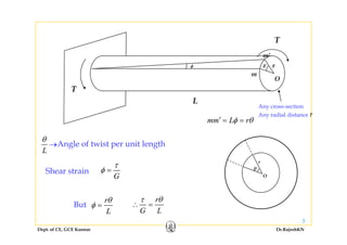


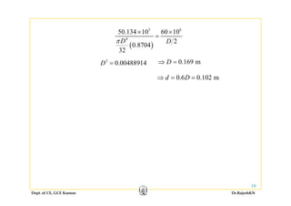


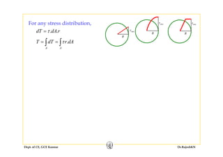
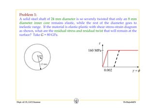
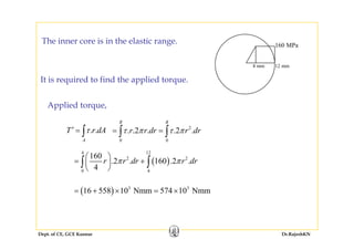


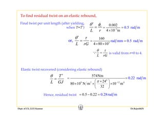

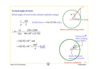
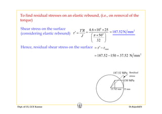
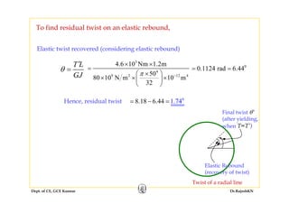


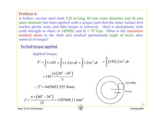
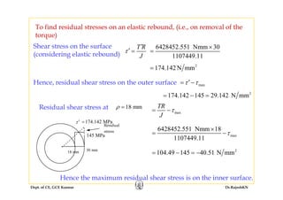

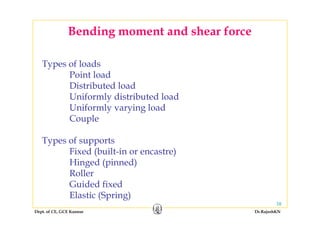

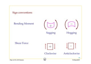


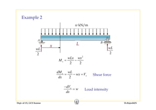
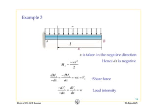
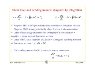
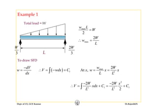

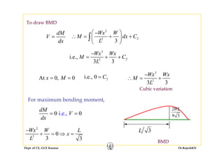
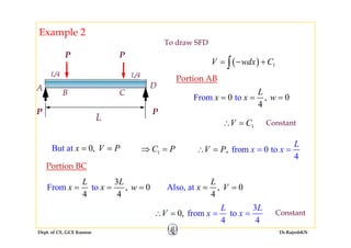


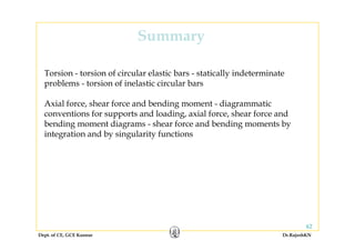

This document discusses mechanics of solids, specifically torsion and bending moment. It begins with an overview and objectives of Module II which covers torsion of circular elastic and inelastic bars, as well as axial force, shear force, and bending moment diagrams. It then provides explanations, equations, and examples relating to torsion, including assumptions in torsion theory, the torsion equation, torsional rigidity, power transmission in torsion, and example problems calculating torque and shaft diameters. It also discusses statically indeterminate shafts and torsion of inelastic circular bars.


![MTORSION [EngineeringDuniya.co MTORSION [EngineeringDuniya.com].pptm].ppt](https://cdn.slidesharecdn.com/ss_thumbnails/mtorsionengineeringduniya-241112074730-b7e902c3-thumbnail.jpg?width=640&height=640&fit=bounds)


![3_torsion [Read-Only] [Compatibility Mode].pdf](https://cdn.slidesharecdn.com/ss_thumbnails/3torsionread-onlycompatibilitymode-240505061844-ecf49736-thumbnail.jpg?width=640&height=640&fit=bounds)