Downloaded 221 times


![58
SUPPLEMENTARY QUESTIONS
Question 1: A cantilever beam is subject to a uniformly distributed load of w N per meter
length. Write the equation of the shearing force and bending moment at any point x along its
length l. Also sketch the shearing force and bending moment diagrams.
Question 2: A simply supported beam which is 4m long is subjected to a uniformly distributed
vertical load of 1600 N/m. Draw the shearing force [S.F]and bending moment [B.M]diagrams.
Question 3:A simply supported beam carries a vertical load that is increasing from zero at one
end to a maximum of 8000 N/m at the other end. Draw the shearing force and bending moment
diagrams.
Question 4: A beam which is 4 m long is simply supported over a span of 2m and overhangs
both supports by a span of 1 m on either side. The right-hand overhanging portion carries a
uniformly distributed load of 80 kN/m and a concentrated load of 20 kN at the extreme end while
the left-hand overhanging portion carries a uniformly distributed load of 40 kN/m and a
concentrated load of 30 kN at the extreme end in addition to a concentrated load of 160 kN at its
mid-span. Draw to scale the S.F and B.M diagrams and find how much may be added to the load
at mid-span without increasing the maximum B.M on the beam.
Question 5: A horizontal beam AB is 8 m long and carries a total uniformly distributed load of
300 kN. The beam is supported at the end A and at a point C which is at a distant x from the
other end B. Determine the value of x if the mid-point of the beam is to be a point of inflexion
and for this arrangement draw the S.F and B.M diagrams, indicating the principal numerical
values of each.
Question 6: A girder 10 m long, carrying a uniformly distributed of w N/m, is to be supported on
two piers 6 m apart so that the greatest bending moment on the girder shall be as small as
possible. Find the distances of the piers from the ends and the maximum bending moment
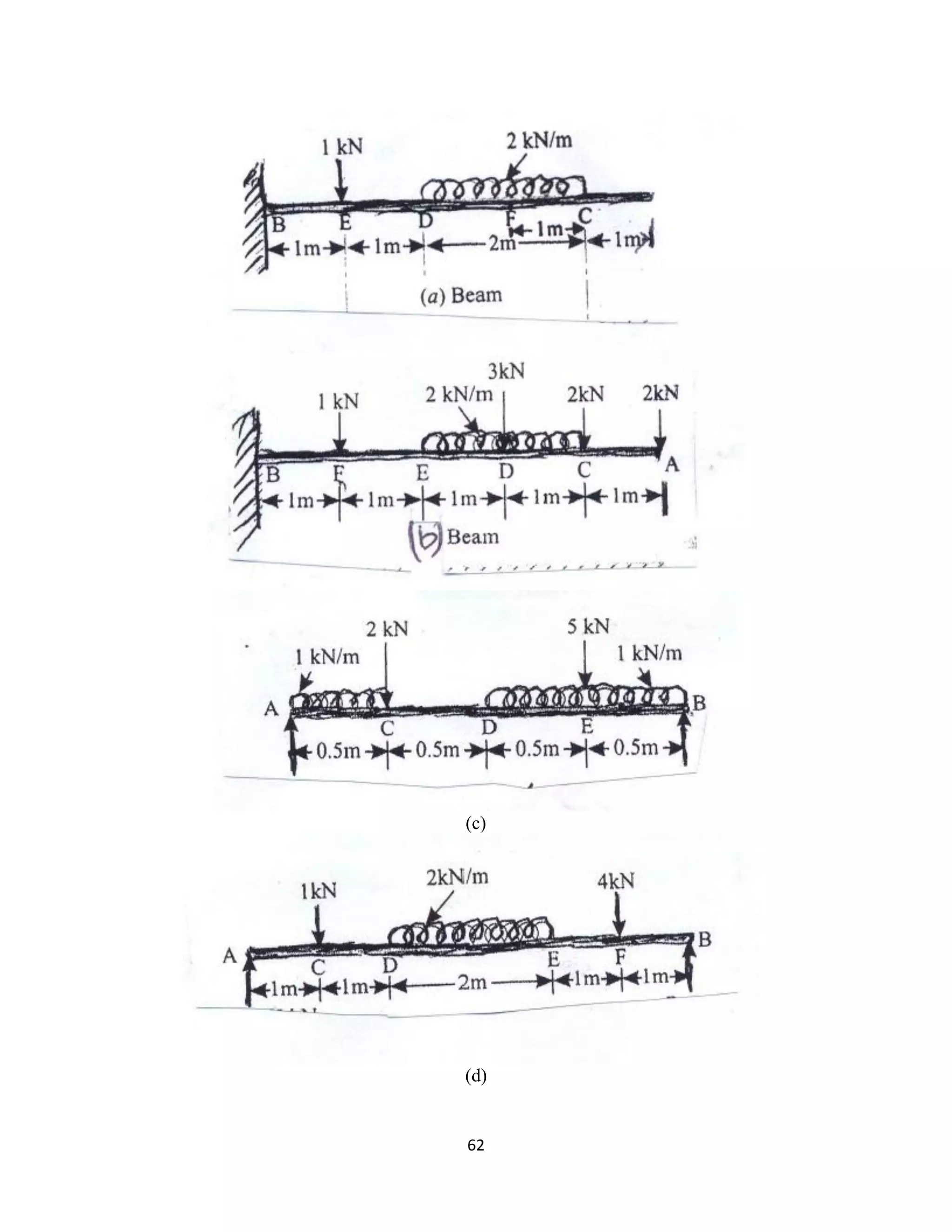
Question 7 A beam is loaded as shown in figure. Find the reactions at A and B also draw S.F
and B.M and thrust diagram](https://image.slidesharecdn.com/mybookae211-180214134418/75/STRENGTH-OF-MATERIALS-for-beginners-59-2048.jpg)


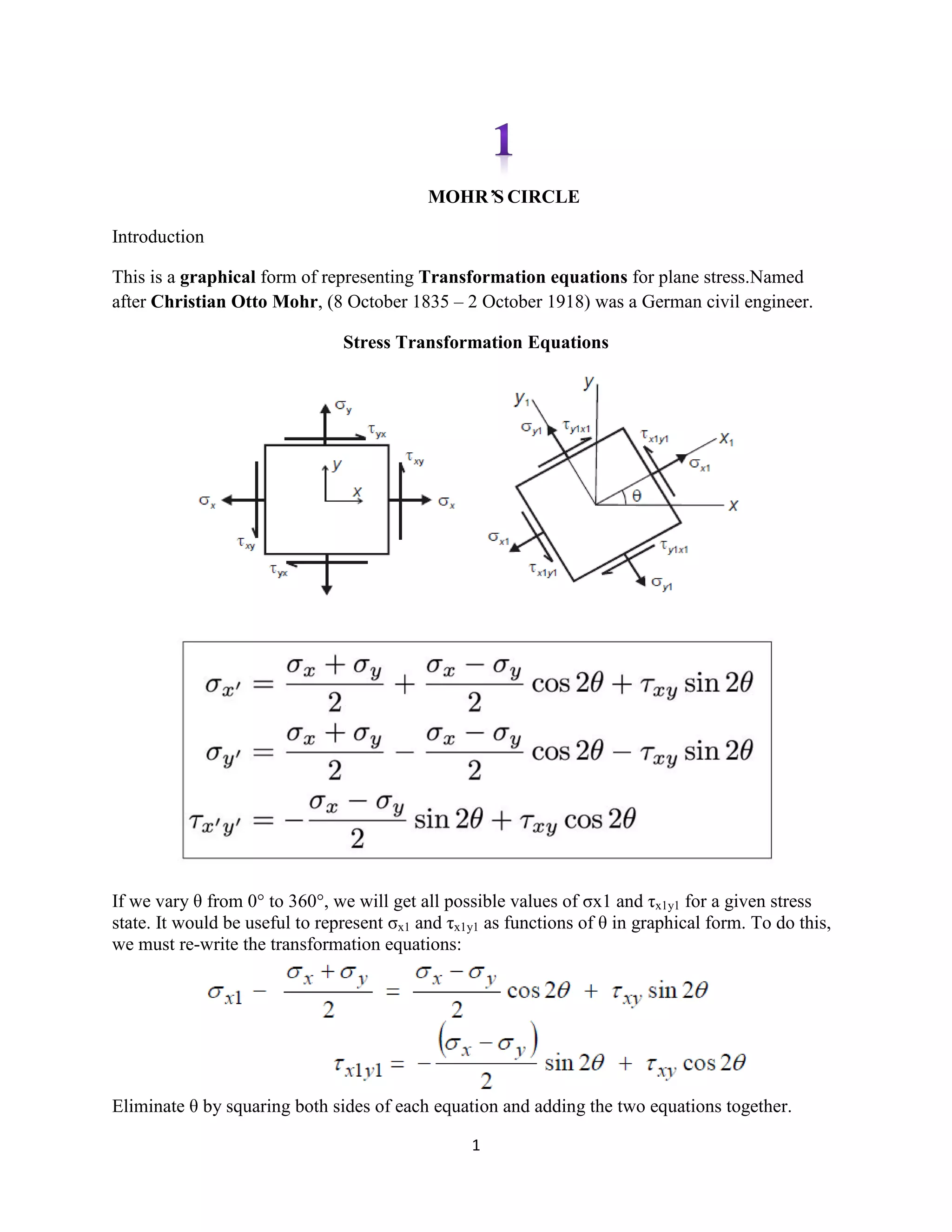
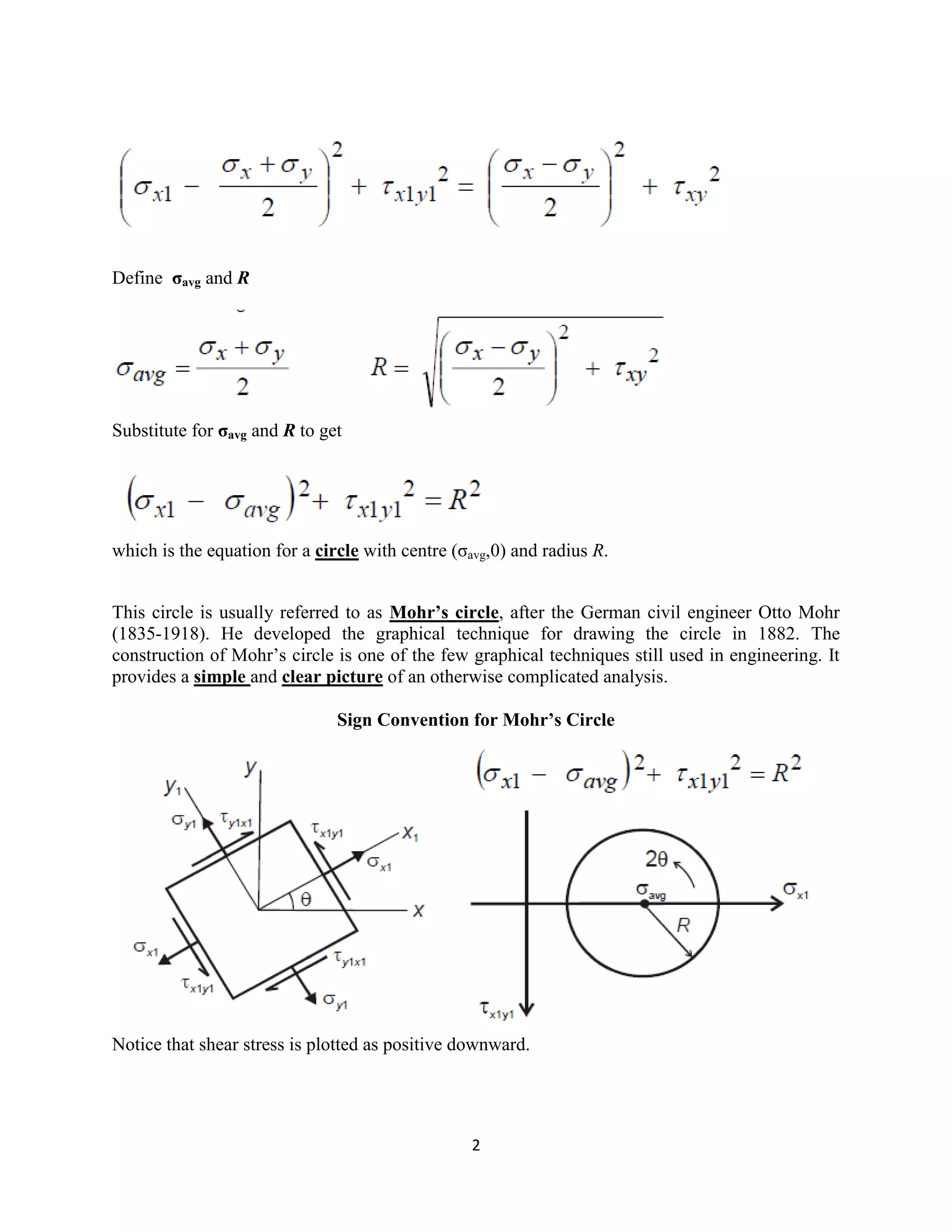
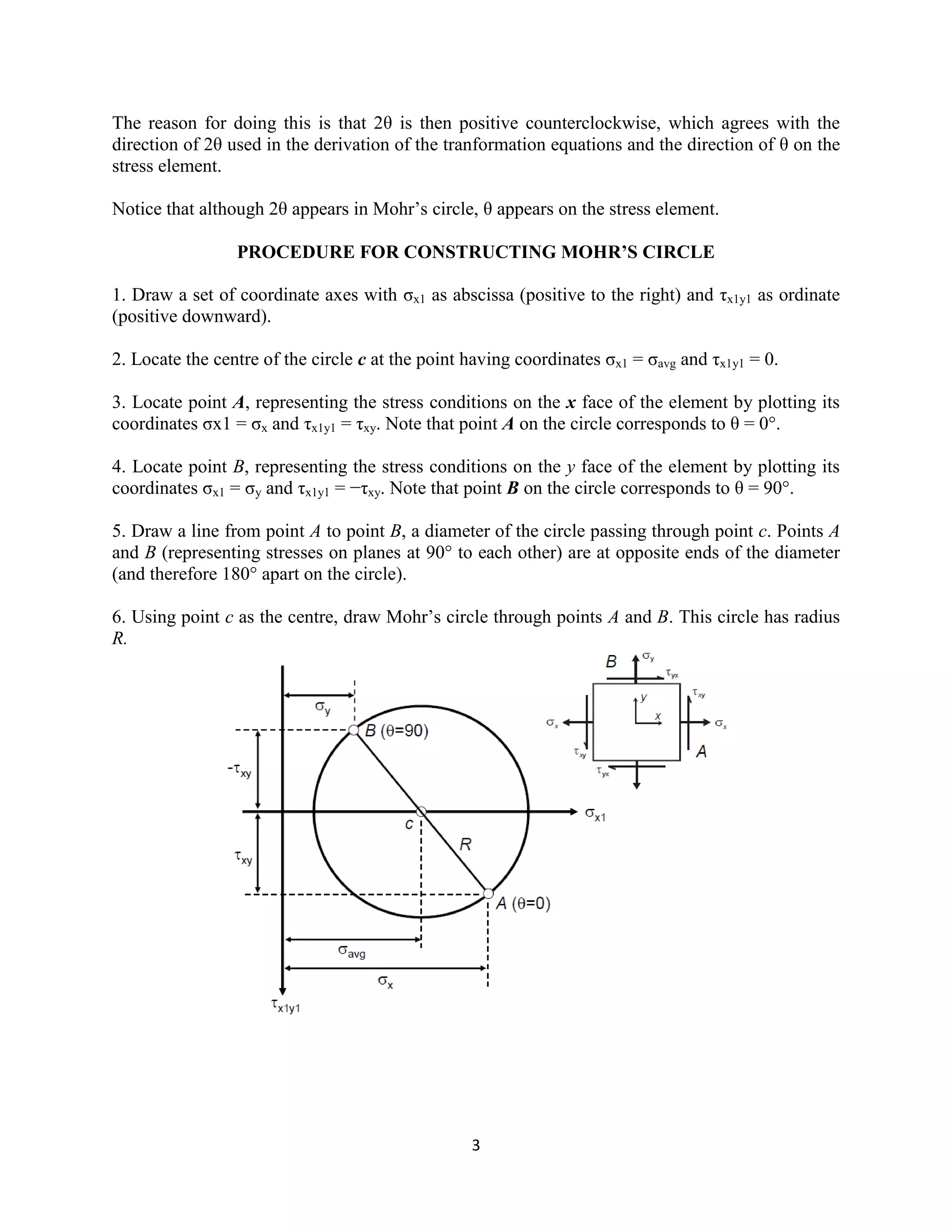
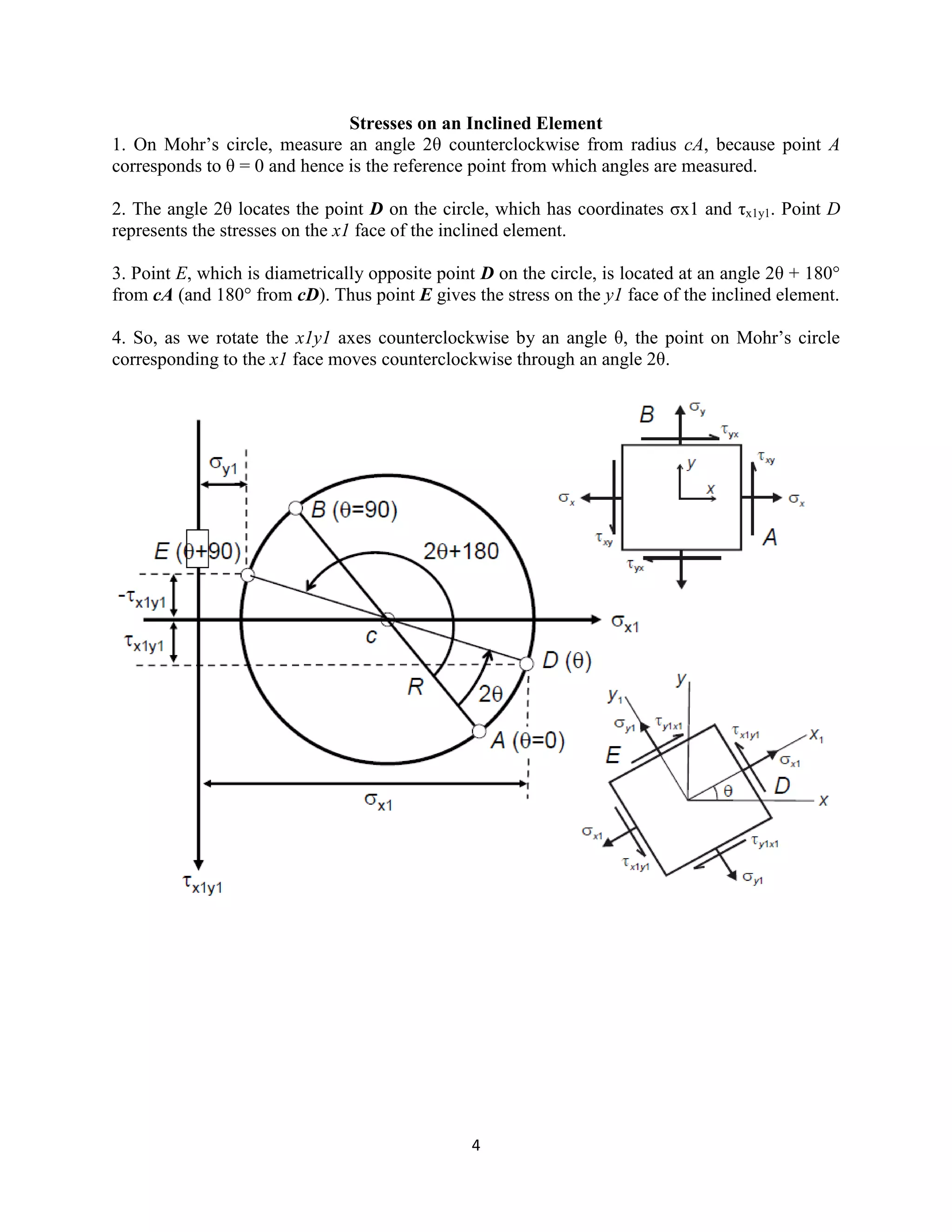
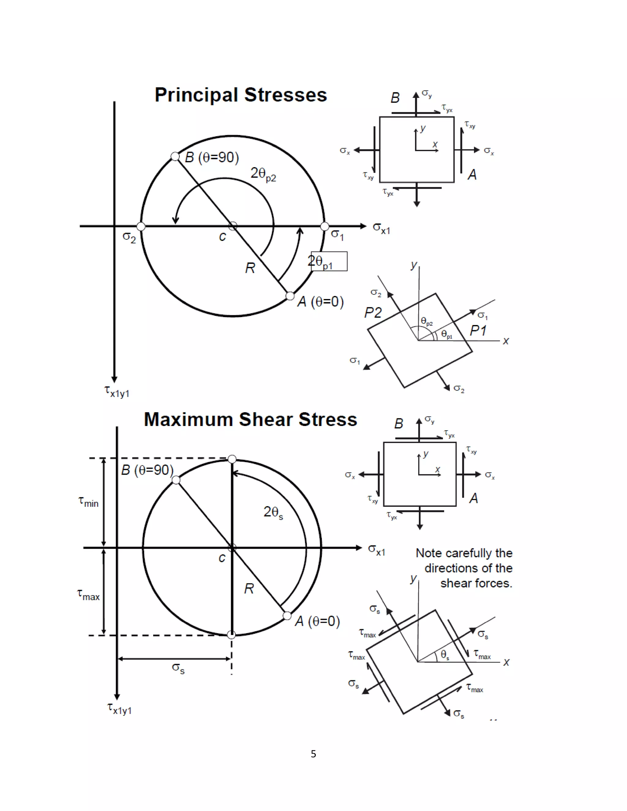
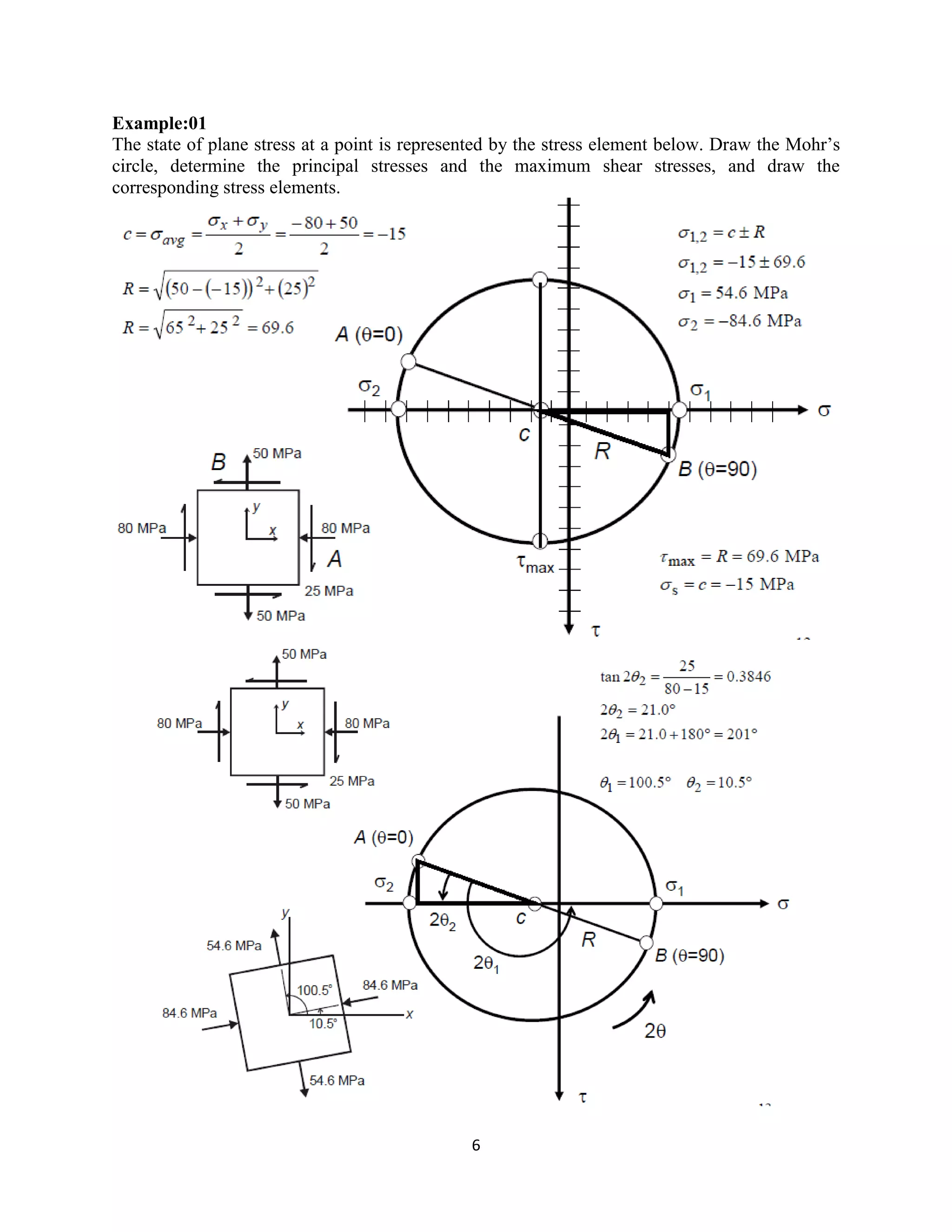
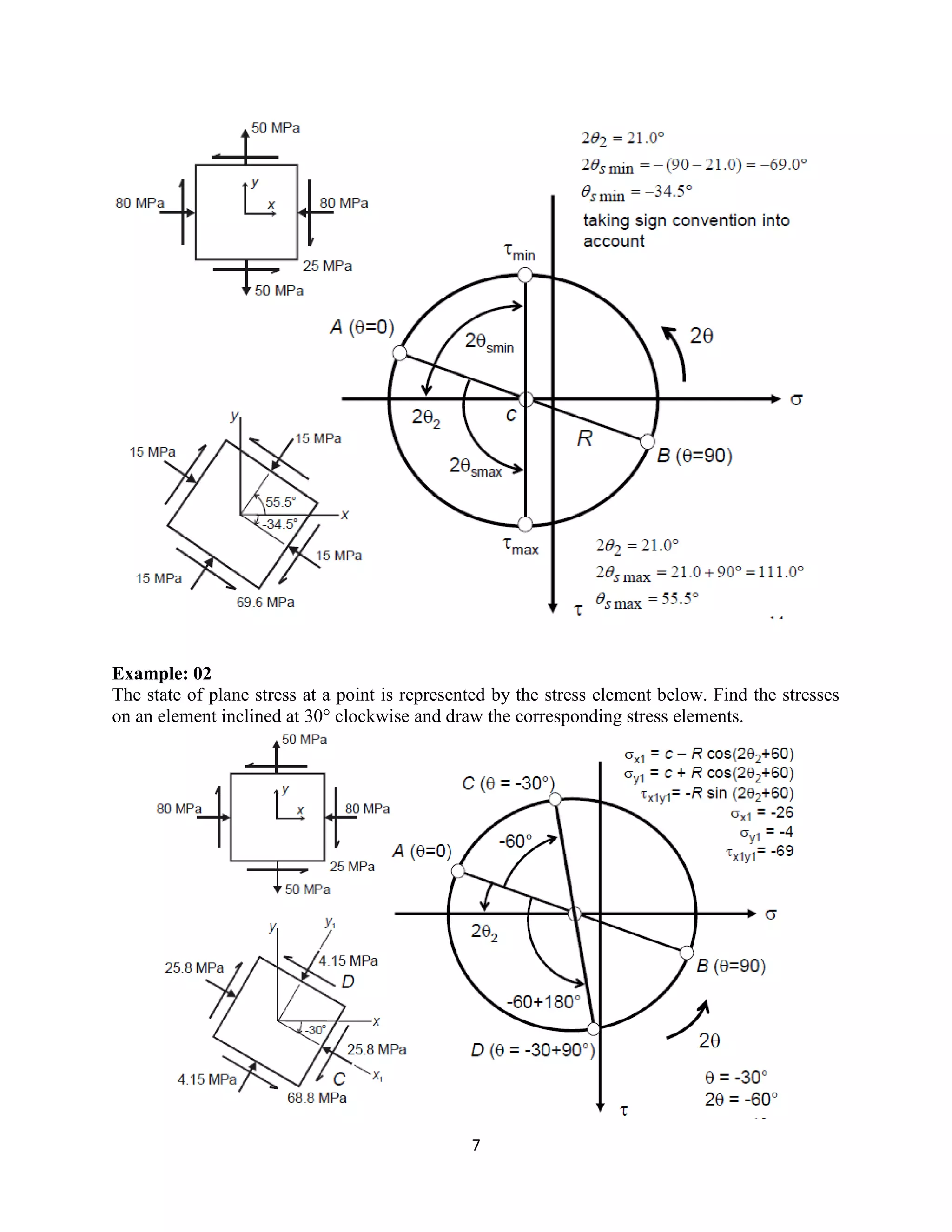
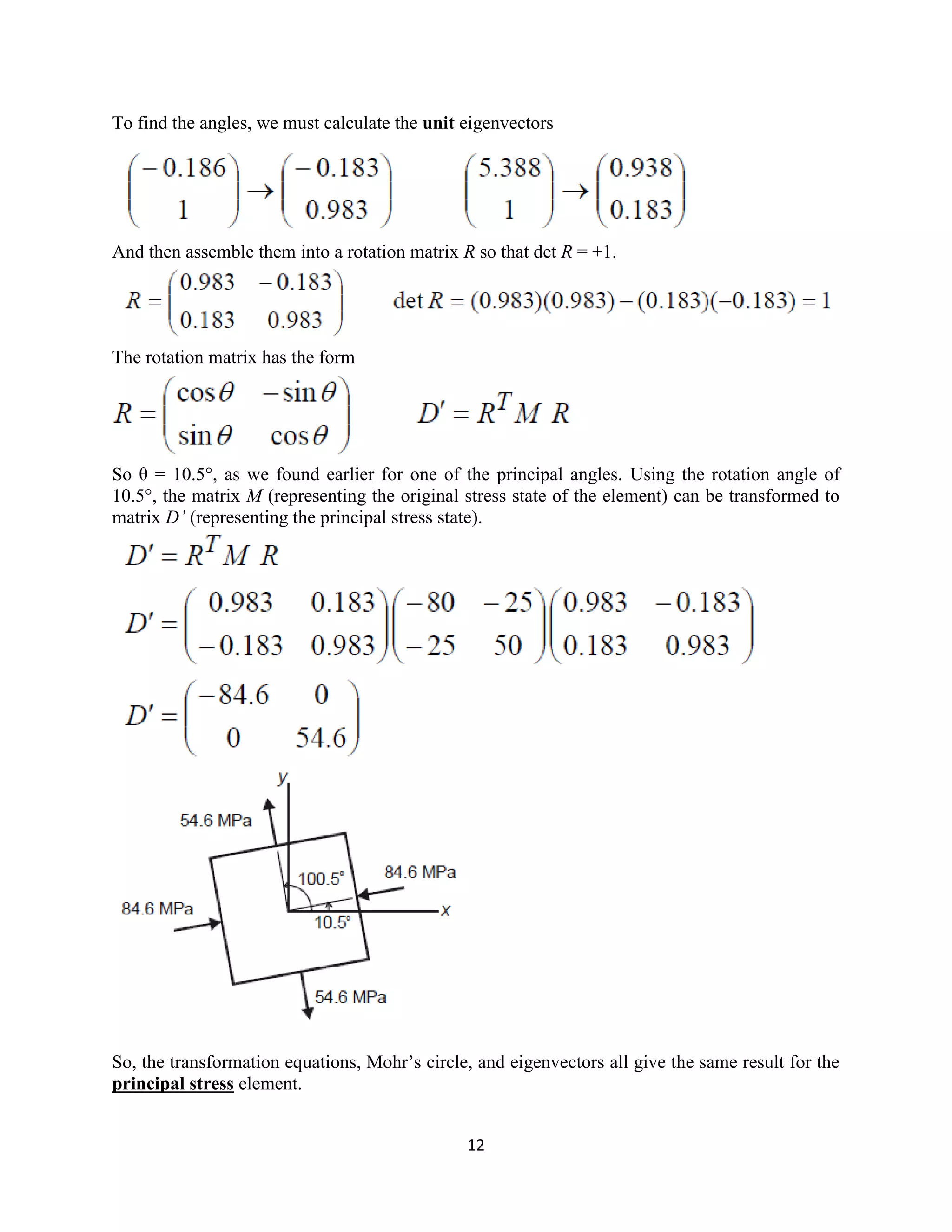
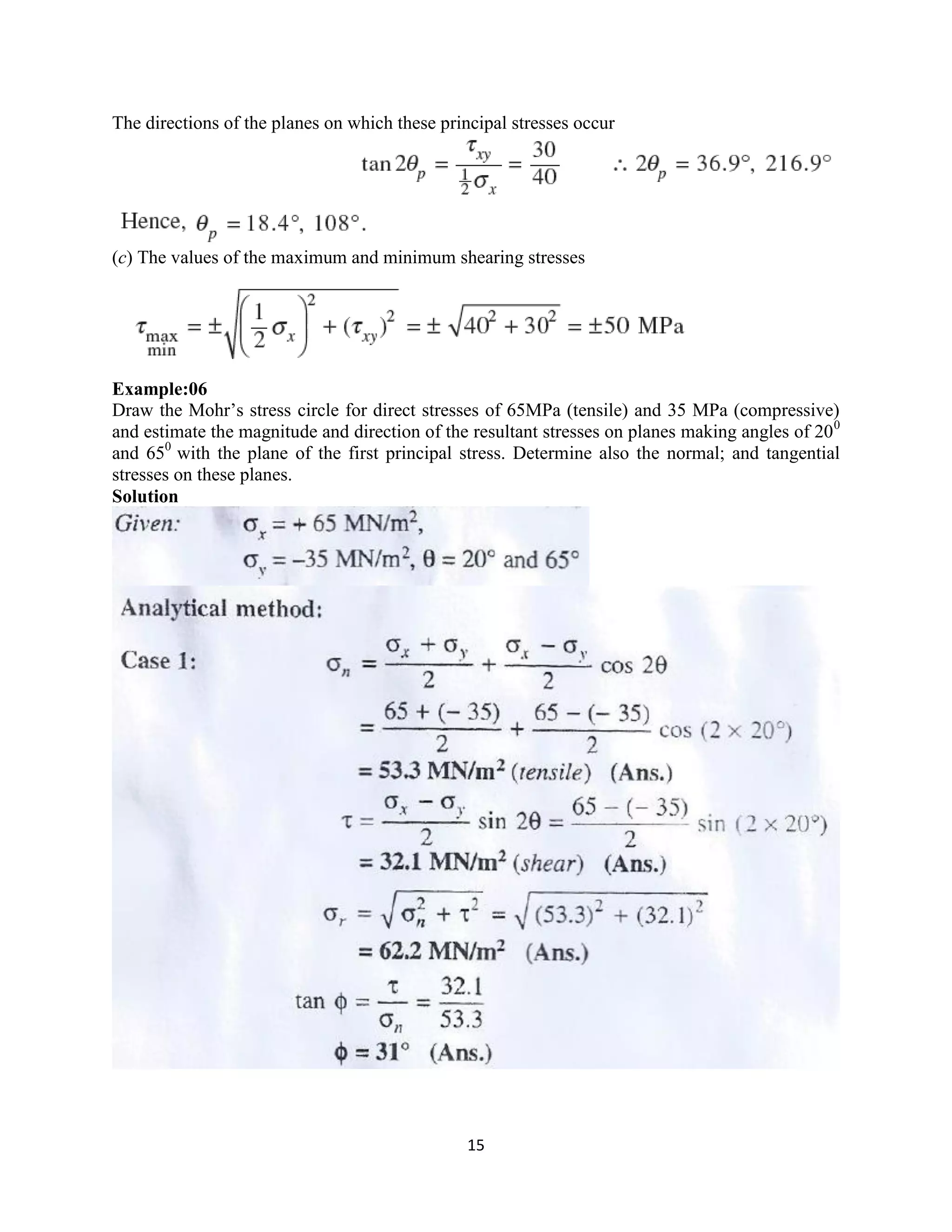
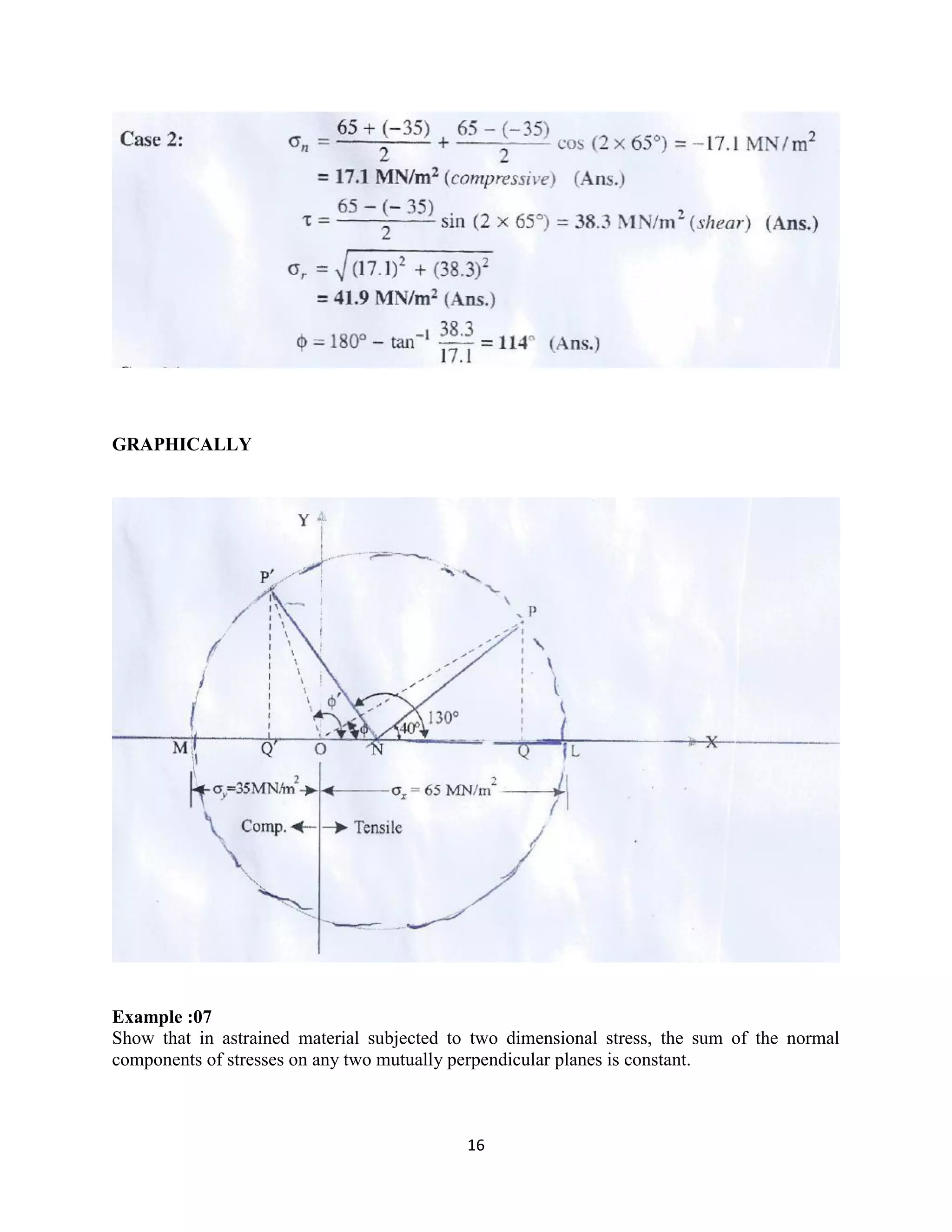
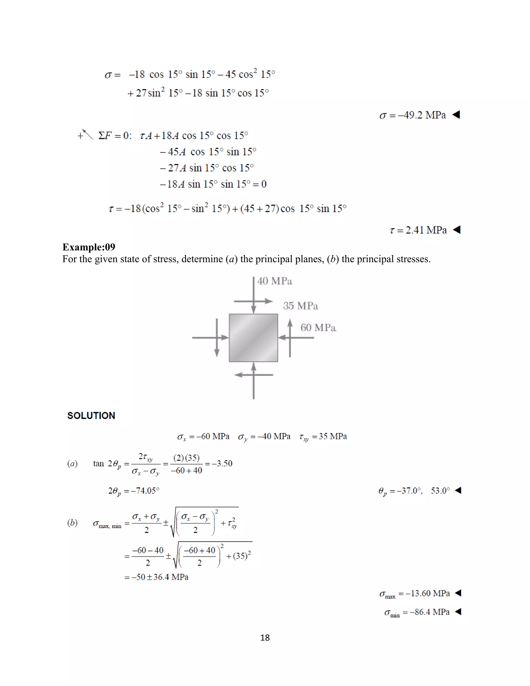
The document provides an introduction to Mohr's Circle and its graphical representation for stress transformation in materials, including procedures for constructing the circle and deriving normal and shear stresses for inclined elements. It covers examples of stress analysis using Mohr's Circle, stress tensors, and discusses beam behavior under various loading conditions. Additionally, it illustrates methods for calculating shear forces and bending moments in beams, with detailed examples showing how to draw shear force and bending moment diagrams.


![CONSTRUCTION [soil treatment, foundation backfill, Damp Proof Membrane[DPM] a...](https://cdn.slidesharecdn.com/ss_thumbnails/kahimba-181220112907-thumbnail.jpg?width=640&height=640&fit=bounds)